Table of Contents
Advertisement
Quick Links
Advertisement
Table of Contents

Subscribe to Our Youtube Channel
Related Manuals for Elektro-Automatik PSI 5000 A


Summary of Contents for Elektro-Automatik PSI 5000 A
- Page 1 Operating Guide PSI 5000 A DC Laboratory Power Supply Attention! This document is only valid for devices with firmware “KE: 3.04” and “HMI: 2.05” Doc ID: PSI5EN or higher. For availability of updates for your device check Revision: 07 our website or contact us.
-
Page 3: Table Of Contents
PSI 5000 A Series TABLE OF CONTENTS OPERATION AND APPLICATION GENERAL Personal safety ..........26 About this document ........4 Operating modes .........26 1.1.1 Retention and use ..........4 3.2.1 Voltage regulation / Constant voltage ..26 1.1.2 Copyright ............4 3.2.2 Current regulation / constant current / current 1.1.3... -
Page 4: General
The manufacturer guarantees the functional competence of the device within the stated performance parameters. The warranty period begins with the delivery of free from defects equipment. Terms of guarantee are included in the general terms and conditions (TOS) of EA Elektro-Automatik GmbH. Limitation of liability All statements and instructions in this manual are based on current norms and regulations, up-to-date technology and our long term knowledge and experience. -
Page 5: Disposal Of Equipment
PSI 5000 A Series Disposal of equipment A piece of equipment which is intended for disposal must, according to European laws and regulations (ElektroG, WEEE) be returned to the manufacturer for scrapping, unless the person operating the piece of equipment or another, delegated person is conducting the disposal. -
Page 6: Safety
PSI 5000 A Series Safety 1.7.1 Safety notices Mortal danger - Hazardous voltage • Electrical equipment operation means that some parts can be under dangerous voltage. Therefore all parts under voltage must be covered! This basically applies to all models, though 40 V models according to SELV can not generate hazardous DC voltage. -
Page 7: Responsibility Of The User
PSI 5000 A Series 1.7.2 Responsibility of the user The equipment is intended for industrial operation. Therefore the operators are governed by the legal safety regulations. Alongside the warning and safety notices in this manual the relevant safety, accident prevention and environmental regulations must also be applied. -
Page 8: Alarm Signals
PSI 5000 A Series 1.7.5 Alarm signals The equipment offers various possibilities for signalling alarm conditions, however, not for danger situations. The signals may be optical (on the display as text) or electronic (pin/status output of an analog interface). All alarms will cause the device to switch off the DC output permanently or temporarily. -
Page 9: Specific Technical Data
PSI 5000 A Series 1.8.3 Specific technical data Model 160 W PSI 5040-10 A PSI 5080-05 A PSI 5200-02 A AC Input Input voltage 90...264 V AC 90...264 V AC 90...264 V AC Input connection 1ph,N,PE 1ph,N,PE 1ph,N,PE Input frequency... - Page 10 PSI 5000 A Series Model 160 W PSI 5040-10 A PSI 5080-05 A PSI 5200-02 A Analog interface Set value inputs U, I, P Actual value output U, I Control signals DC output on/off, remote control on/off Status signals CV, OVP, OT, PF Galvanic isolation to the device Max.
- Page 11 PSI 5000 A Series Model 320 W PSI 5040-20 A PSI 5080-10 A PSI 5200-04 A AC Input Input voltage 90...264 V AC 90...264 V AC 90...264 V AC Input connection 1ph,N,PE 1ph,N,PE 1ph,N,PE Input frequency 50/60 Hz 50/60 Hz...
- Page 12 PSI 5000 A Series Model 320 W PSI 5040-20 A PSI 5080-10 A PSI 5200-04 A Analog interface Set value inputs U, I, P Actual value output U, I Control signals DC output on/off, remote control on/off Status signals CV, OVP, OT, PF Galvanic isolation to the device Max.
- Page 13 PSI 5000 A Series Model 640 W PSI 5040-40 A PSI 5080-20 A PSI 5200-10 A AC Input Input voltage 90...264 V AC 90...264 V AC 90...264 V AC - with additional derating 90...150 V AC 90...150 V AC 90...150 V AC...
- Page 14 PSI 5000 A Series Model 640 W PSI 5040-40 A PSI 5080-20 A PSI 5200-10 A Analog interface Set value inputs U, I, P Actual value output U, I Control signals DC output on/off, remote control on/off Status signals CV, OVP, OT, PF Galvanic isolation to the device Max.
-
Page 15: Views
PSI 5000 A Series 1.8.4 Views Figure 1 - Front side Figure 2 - Back side The brass screw next to the AC connector is a central grounding point for internal use! Do not unscrew to connect external PE potential here! The device is grounded via the AC cable. - Page 16 PSI 5000 A Series EA Elektro-Automatik GmbH Fon: +49 2162 / 3785-0 www.elektroautomatik.de Page 16 Helmholtzstr. 31-37 • 41747 Viersen Fax: +49 2162 / 16230 ea1974@elektroautomatik.de Germany...
-
Page 17: Control Elements
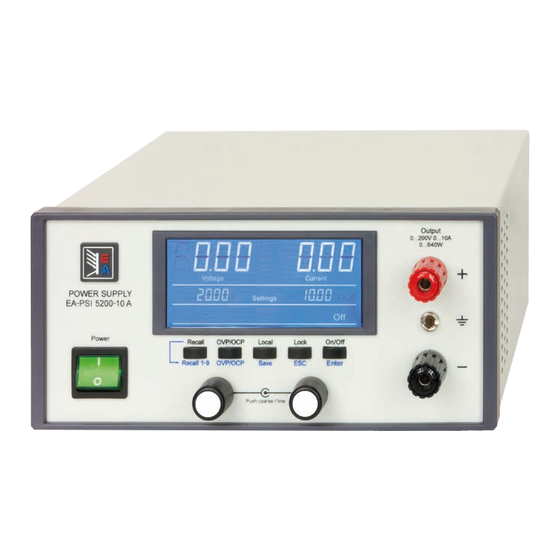
PSI 5000 A Series 1.8.5 Control elements Figure 5 - Control panel Overview of the elements of the control panel For a detailed description see section „1.9.4. The control panel (HMI)“. Display Used for indication of set values, actual values and status. -
Page 18: Construction And Function
1.9.1 General description The electronic DC laboratory power supplies of the PSI 5000 A series are especially suitable for laboratories, workshops, school and other educational facilities due to their compact construction in a desktop enclosure. For remote control using a PC or PLC the devices are provided as standard with a 3-way interface on the rear side. - Page 19 PSI 5000 A Series The left hand rotary knob is assigned either to the output voltage and related parameter OVP or the power and the related parameter OPP, whereas the right hand rotary knobs is always assigned to the output current and related parameter OCP.
-
Page 20: Usb Port
PSI 5000 A Series 1.9.5 USB port The USB port on the back side of the device is provided for communication with the device and for firmware updates. The included USB cable can be used to connect the device to a PC (USB 2.0, USB 3.0). The driver is delivered on the included USB stick or is available as download and installs a virtual COM port. -
Page 21: Installation & Commissioning
Preparation Mains connection for a PSI 5000 A series device is done via the included 1.5 meters long 3 pole mains cord. It is required to operate the device with this or a similar cord which features a ground conductor. The ground is important for safety and radio interference suppression. -
Page 22: Connection To Ac Supply
PSI 5000 A Series 2.3.3 Connection to AC supply • The device can be connected to any wall socket or power strip, as long as those feature a ground conductor (PE) • When connecting the device to a power strip, along with other electric devices, it is important to consider the total power consumption of all devices on the strip, so that the maximum current (power ÷... -
Page 23: Grounding Of The Dc Output
PSI 5000 A Series 2.3.5 Grounding of the DC output Grounding one of the DC output poles is allowed. Doing so can result in a potential shift of the grounded pole against PE. Because of insulation, there is a max. allowed potential shift of the DC output poles, which also depends on the device model. -
Page 24: Connecting The Analog Interface
PSI 5000 A Series 2.3.7 Connecting the analog interface The 15 pole connector (Type: Sub-D, D-Sub) on the rear side is an analog interface. To connect this to a control- ling hardware (PC, electronic circuit), a standard plug is necessary (not included in the scope of delivery). It is generally advisable to switch the device completely off before connecting or disconnecting this connector, but at least the DC output. -
Page 25: Initial Network Setup
PSI 5000 A Series 2.3.10 Initial network setup The device is delivered with default network parameters. The Ethernet/LAN port is immediately ready for use after the initial commission. Default parameters: IP: 192.168.0.2 Subnet mask: 255.255.255.0 Gateway: 192.168.0.1 Port: 5025 DHCP: off For wiring, i.e. -
Page 26: Operation And Application
PSI 5000 A Series Operation and application Personal safety • In order to guarantee safety when using the device, it is essential that only persons operate the device who are fully acquainted and trained in the required safety measures to be taken when working with dangerous electrical voltages • Whenever the load and DC output connection are being re-configured, the device should be... -
Page 27: Alarm Conditions
PSI 5000 A Series Alarm conditions This section only gives an overview about device alarms. What to do in case your device indicates an alarm condition is described in section „3.6. Alarms and supervision“. As a basic principle, all alarm conditions are signalled optically (in the display) and as a readable status via the digital interface. -
Page 28: Manual Operation
PSI 5000 A Series Manual operation 3.4.1 Switching the device on The device should, as far as possible, always be switched on using the toggle switch on the front of the device. Alternatively this can take place using an external cutout (contactor, circuit breaker) of suitable current capacity. -
Page 29: Manually Configure Protections
PSI 5000 A Series 3.4.4 Manually configure protections Along with adjustable set values, the device offers excess protections related to voltage, current and power, which are intended to protect the possibly expensive load hardware. They are configurable in form of adjustable thresh- olds that the device supervises and in case of excess it will switch off the DC output. -
Page 30: Recall Feature
PSI 5000 A Series 3.4.6 Recall feature The recall feature is intended to easily recall presets of often used set values (U, I) and protection thresholds (OVP, OCP), except the power set value and OPP threshold. With this, the user can switch between the presets without having to adjust every time again. -
Page 31: Remote Control
PSI 5000 A Series Remote control 3.5.1 General Remote control is principally possible via any of the built-in interface ports (USB, Ethernet/LAN, analog). Important here is that only the analog or one digital interface can be in control. It means that if, for example, an attempt were to be made to switch to remote control via the digital interface whilst analog remote control is active (pin Remote = LOW) the device would report an error at the digital interface. - Page 32 PSI 5000 A Series Alternatively to setting network parameters manually, DHCP can be activated by command and used by a DHCP server in the network to dynamically assign them. The network setup can be done manually or by DHCP. The transmission speed is set to “Auto negotiation” and means it can use 10MBit/s or 100MBit/s.
-
Page 33: Remote Control Via The Analog Interface (Ai)
PSI 5000 A Series 3.5.4 Remote control via the analog interface (AI) 3.5.4.1 General The built-in, up to 1500 V DC galvanically isolated, 15-pole analog interface (short: AI) is on the rear side of the device offers the following possibilities: • Remote control of current, voltage and power... - Page 34 PSI 5000 A Series 3.5.4.4 Analog interface specification Pin Name Type* Description Levels Electrical properties 0…10 V or. 0...5 V corre- VSEL Set voltage value Accuracy 0-5 V range: < 0.4% **** spond to 0..100% of U Accuracy 0-10 V range: < 0.2% **** 0…10 V or.
- Page 35 PSI 5000 A Series 3.5.4.6 Simplified diagram of the pins Digital Input (DI) Analog Input (AI) The internal circuit requires that a switch High resistance input (impedance V~0.5 with low resistance should be used (relay, >40 k..100 kΩ) for an OA circuit.
- Page 36 PSI 5000 A Series In case the DC output is already switched on, toggling the pin will switch the DC output off, similar to what it does in analog remote control: Parameter Behaviour output „REM-SB“ „REM-SB“ DC output remains on, nothing is locked. It can be switched on...
-
Page 37: Alarms And Supervision
PSI 5000 A Series Alarms and supervision 3.6.1 Definition of terms Device alarms (see „3.3. Alarm conditions“) are defined as conditions like overvoltage or overtemperature, which can occur in relation to protection feature with partly adjustable thresholds. The alarms are always indicated in the front display and are as well available as readable status via digital interface when controlling or just monitoring remotely. -
Page 38: Other Applications
PSI 5000 A Series Other applications 3.7.1 Parallel operation Multiple devices of same kind and model can be connected in parallel in order to create a system with higher total current and hence higher power. There is no support from hardware or software for this kind of operation, specifically regarding voltage regulation and current balancing. -
Page 39: Service And Maintenance
PSI 5000 A Series Service and maintenance Maintenance / cleaning The device needs no maintenance. Cleaning may be needed for the internal fans, the frequency of cleanse is depending on the ambient conditions. The fans serve to cool the components which are heated by the inherent power loss. -
Page 40: Contact And Support
PSI 5000 A Series Contact and support General Repairs, if not otherwise arranged between supplier and customer, will be carried out by the manufacturer. For this the device must generally be returned to the manufacturer. No RMA number is needed. It is sufficient to package the equipment adequately and send it, together with a detailed description of the fault and, if still under guarantee, a copy of the invoice, to the following address. - Page 42 EA-Elektro-Automatik GmbH & Co. KG Development - Production - Sales Helmholtzstraße 31-37 41747 Viersen Germany Fon: 02162 / 37 85-0 Mail: ea1974@elektroautomatik.de Web: www.elektroautomatik.de...
Need help?
Do you have a question about the PSI 5000 A and is the answer not in the manual?
Questions and answers