Table of Contents
Advertisement
Quick Links
操 作 指 南
Operating Guide
PSI 8000 DT
Laboratory DC Power Supply
实验室直流电源
PSI 8016-20DT:
PSI 8032-10DT:
PSI 8065-05DT:
PSI 8032-20DT:
PSI 8065-10DT:
09 200 410
PSI 8160-04DT:
09 200 411
PSI 8080-40DT:
09 200 412
PSI 8080-60DT:
09 200 413
PSI 8360-10DT:
09 200 414
PSI 8360-15DT:
09 200 415
09 200 416
09 200 417
09 200 418
09 200 419
Advertisement
Chapters
Table of Contents

Related Manuals for Elektro-Automatik PSI 8000 DT


Summary of Contents for Elektro-Automatik PSI 8000 DT
- Page 1 操 作 指 南 Operating Guide PSI 8000 DT Laboratory DC Power Supply 实验室直流电源 PSI 8016-20DT: 09 200 410 PSI 8160-04DT: 09 200 415 PSI 8032-10DT: 09 200 411 PSI 8080-40DT: 09 200 416 PSI 8065-05DT: 09 200 412 PSI 8080-60DT:...
- Page 3 担该行为导致的法律后果。 本产品输出电压可能上升至危险级别(>60V )! 产品上所有带电元件必须有外遮盖。输出端的所有操作必须在 产品与主电源(电源开关关闭)断开时才能执行,且可只有受 训过电流危险知识的专业人员执行此类操作。负载与本产品间 的任何连接必须有防碰擦装置。连到功率输出端的应用设备必 须配置好,并且有保险丝熔断保护,这样可防止使用过程中由 于过载或误操作损坏产品或更严重事情发生。 注意! 产品或输出关闭后,直流输出端在一定时间内仍存在危险电 压! 请谨记 • 请仅在铭板标示电压下操作本产品。 • 请勿将任何机械零件,特别是金属件,插入通风孔内。 • 请不要在本产品周围使用任何液体物质,以免进入产品内。 • 请勿将高于电源供应器额定电压的电压源连接到产品上。 • 从后板插槽安装接口卡时,请遵循一般防静电规则。 • 只能在产品完全关闭(电源开关为关闭状态)后插入和取出 接口卡。 • 产品老化以及超负荷使用都可能导致如按钮、旋钮类的产 品控制件操作不稳定。 • 请勿将电压源反接到直流输出端!产品可能会被损坏。 • 请勿将那些可能会产生高于产品额定电压的电压源连到直 流输出端! PSI 8000 DT 系列 日期:31-03-2014 产品说明书...
-
Page 4: Table Of Contents
电流监控 ..................22 7.6.3 阶跃响应监控 ..................23 恢复至默认配置 ..................24 解锁U/I/R运行模式 ..................24 锁定产品配置 ..................24 © 2006, Elektro-Automatik GmbH & Co. KG Irrtümer und Änderungen vorbehalten 8. 数字接口卡 ....................25 一般信息 ....................25 配置接口卡 .................... 25 9. 内置模拟接口 ....................25 一般信息... - Page 5 串联 ....................28 11.1.2 共享总线下的并联 .................. 29 11.1.3 混合连接 ..................29 11.2 连网 ....................31 12. 附件 ...................... 31 12.1 其它附件和选项功能 ..................31 12.2 固件更新 ....................31 12.3 选项:内阻 .................... 32 12.4 难题解答 ....................32 PSI 8000 DT 系列 日期:31-03-2014 产品说明书...
-
Page 6: 技术规格
2ms to 9.999 s 范围1: 10ms to 59.99s 范围2: 1:00m to 59:59min 范围3: 1:00h to 99:59h 范围4: 精确度: 范围1: 10ms 范围2: 范围3: 1 min 范围4: © 2006, Elektro-Automatik GmbH & Co. KG Irrtümer und Änderungen vorbehalten PSI 8000 DT 系列 日期:31-03-2014 产品说明书... -
Page 7: 各型号详细规格
EN 61326, EN 55022 等级 B EMC标准 等级 II 过压等级 等级 I 保护等级 模拟编程 电压范围 0…5V 或 0…10V (可选) 设定/实际值精确度 ≤ 0.2% 输入阻抗 约 53kΩ * 与额定值有关,该精确度决定设定值与实际值间允许最大误差。 产品编号 09200410 09200411 09200412 09200413 09200414 举例:一台65V型号产品的电压精确度最少为0.2%,即为130mV。当设定5V电压时,且允许最大误差为130mV, 故得出实际值可能在4.87V和5.13V.之间。 ** 可解锁,选项功能 PSI 8000 DT 系列 日期:31-03-2014 产品说明书... - Page 8 -输出对PE的隔离耐压 300V DC 串联 可行(但有限制) 可执行,经该共享总线可最多连接1000W以上的30台产品 并联 湿度 <80% 安全标准 EN 60950 © 2006, Elektro-Automatik GmbH & Co. KG EN 61326, EN 55022 等级 B EMC标准 Irrtümer und Änderungen vorbehalten 过压等级 等级 II 保护等级 等级 I 模拟编程 电压范围 0…5V 或 0…10V (可选) ≤...
-
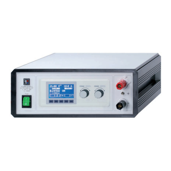
Page 9: 产品描述
关于电源 3. 产品描述 各面视图 图 1. 前视图 图 2. 后视图 图 3. 右视图t PSI 8000 DT 系列 日期:31-03-2014 产品说明书... -
Page 10: 插图说明
注意! 自行承担风险。 只有受过电流危险知识训练的人员方可进行相关的维护或修理。 (+) 感测端只能与负载设备(+)端相连,(–)感测端与(–)端 相连!否则会损坏两头的产品。 5. 安装 。 详情也可参考章节“10.1 远程感测” 目检 接口卡插槽 收到本产品后,请检查是否有外观受损痕迹。如有,请不要操 可选择给本产品配上接口卡。接口卡插槽位于产品后端。更多 作本产品,应立即联系您的供应商。 信息见章节“8. 数字接口卡”。 与市电的连接 本产品通过电源线接地。故仅可与带接地触点的电源插座相连。 且连线中间不可接无接地触点的延伸线! 还装有5x20mm的保险丝(具体数值请看规格参数表),装于产品 后板的保险座内。 © 2006, Elektro-Automatik GmbH & Co. KG Irrtümer und Änderungen vorbehalten PSI 8000 DT 系列 日期:31-03-2014 产品说明书... -
Page 11: 显示器
章节的步宽)或细调(始终为最右边的数字)。粗调和细调见得 转换通过左旋钮上的按钮完成。 Displayed only,所有只显示,代表状态的元素以这个 符号标识 = Parameter,可更改值以该符号标识,且表示强调 设定电流 Menu items,可选择,指向下个分级或带参数的最低级 期望是出电流的目标值(右旋钮)。可对该值粗调(见“6.6 调 {…}括号表示可能的选项或参数的调节范围。 节设定值”章节的步宽)或细调(始终为最右边的数字)。粗调 和细调见得转换通过右旋钮上的按钮完成。要调节设定值必须 先按 按钮。 设定功率(1kW以上型号) 期望最大输出功率的目标值(右旋钮)。要设定该值,必须在 之前就按下 按钮。 设定内阻(选项) 期望内阻的目标值(右旋钮)。如果内阻控制解锁,且在产品 设置下选择了U/I/R模式,该设定值替代功率设定值。要设定该 值,必须先按下 按钮。 图 4 PSI 8000 DT 系列 日期:31-03-2014 产品说明书... -
Page 12: 打开电源
右旋钮既可以设置电流、功率(1kW型号起)设定值,也可以 进行远程控制 设置内阻设定值(当选择了模式,且该模式已解锁)。选定的 设定值反向显示于屏幕上。 extern 通过模拟接口远程控制 用选择键 打开电源 选择功率设定值,或者用 电源开关启动仪器。打开后,显示屏上显示产品型号,如果是 程控型,再显示用户文本。 选择内阻设定值,或者 通过其中一个数字接口卡,利用LabView VI进入用户文本,该文 本可在多组产品同时使用的复杂环境下辨别每个产品。 选定电流设定值。 当识别和进入内部系统后,电源的最后状态(设定值,报警管 可限制最大可调功率。 理等)被存储。主电源断电(供电故障)又恢复后或产品重新启 Profile菜单中设置。 动后,输出状态可在 © 2006, Elektro-Automatik GmbH & Co. KG Irrtümer und Änderungen vorbehalten PSI 8000 DT 系列 日期:31-03-2014 产品说明书... -
Page 13: 转换按钮面板
10mA 0.5A 10mA 功率 阻值 额定值 粗调 细调 最大值 粗调 细调 1000W 16Ω 0.1Ω 10mΩ 1500W 26,7/32/40Ω 0.2Ω 10mΩ 64Ω 0.5Ω 10mΩ 130Ω 1Ω 100mΩ 260Ω 2Ω 100mΩ 480/720/800Ω 5Ω 100mΩ 960Ω 5Ω 100mΩ PSI 8000 DT 系列 日期:31-03-2014 产品说明书... -
Page 14: 激活菜单
I> def. def. def. 超过过流监控阀值 I< def. def. def. 超过欠流监控阀值 U def. def. def. 正向电压转换时设定值比较出错 © 2006, Elektro-Automatik GmbH & Co. KG U def. def. def. 负向电压转换时设定值比较出错 Irrtümer und Änderungen vorbehalten I def. def. def. 正向电流转换时设定值比较出错 I def. def. def. -
Page 15: 报警和警戒的确认
过接口卡的链接控制函数管理器,其特点:您可在函数将要停 函数管理器用于创建自动控制电源供应器的函数。函数f(U, I, 止的地方设置一暂停点。 ∆t)建立后可将设定值转成曲线图。函数管理器每隔2ms设置设 定值,意指只有2ms的倍数时间才能设定,比如:50ms。如 果两点间的电压或电流改变,将形成一个由一定步骤组成的跳 跃。(∆t:2ms,形成25个步骤,如果设定值是50ms的话) 函数管理器控制电源,输入配置在函数内的设定值。输出值的 实际发展由负载决定。 使用术语解释: Setup function开 函数=由多达5组连接的序列头(在菜单 始)构成,而一个函数可组成多达五组不同的配置序列。 函数排布=通过函数管理器在函数布局下的配置,可设定电源 操作模式(U/I/P 或 U/I/R)。而且还可在此处设定函数的重复率 和序列的任意秩序。根据函数布局,函数管理器在上个序列完 成后处理下一列,并使用下列的序列控制设定值。 序列=由序列控制和10个序列点构成。如果函数管理器即将处 理一序列,首先设定序列控制给出的参数,连续设定10个序列 点,按照某特定序列设定的重复率,重复整个处理程序。 Sequence control)) =定义序列重复率和序列 序列控制( 处理过程中最大功率设定值与内阻(选项,必须解锁)。 函数管理器显示总图: 图 5 PSI 8000 DT 系列 日期:31-03-2014 产品说明书... -
Page 16: 配置函数
菜单页 Sequence {1..5} + 指向下列菜单选项: Sequence {1..5} (要编辑的序列数) Sequence control Sequence points 0-4 Sequence points 5-9 © 2006, Elektro-Automatik GmbH & Co. KG 此处可设置序列重复率,最大功率和内阻(可选,要解锁),以 Irrtümer und Änderungen vorbehalten 及序列点。 PSI 8000 DT 系列 日期:31-03-2014 产品说明书... -
Page 17: 函数运行时的显示
1500kW 。 屏幕右边 比如:待机时的模拟显示如下: 显示函数运作的状态,函数(1)和序列(2)的剩余 重复次数,当前序列号(2/_)和现时运行的序列点(_/5)。 表示函数管理器暂停或尚未开始。 函数管理器正在运行。 15:05 m 函数发生器启动后的累计时间也会显示出 来。函数管理器停止,时间显示才停止。STEP,RUN或GO 键以多种方式操作函数管理器,同时时间显示会持续累计。 {ON,OFF} 电源输出状态 除电源输出状态外,还显示报警,警戒或信号提示状态。 6.15.7 函数管理器的控制 用GO键继续运行停止后的函数。 交互式控制面板给函数管理器提供多个控制键。利用这些按键 用户可暂停、继续、重设为起始点或退出函数管理器。 或者用NEW键可重设函数管理器,开始执行当前函 数。 函数管理器真正设定电源前,可在显示屏幕上模拟此函数。在 此操作过程中 - 不可打开输出,且 - 一步一步处理这些序列点,并按相同方法检验。 PSI 8000 DT 系列 日期:31-03-2014 产品说明书... -
Page 18: 产品设置
Load profile Step response Save profile General settings + Load profile + © 2006, Elektro-Automatik GmbH & Co. KG Load profile from user profile = {default, 1..4} General settings菜单,指向下列选项,可配置操作模 进入 Irrtümer und Änderungen vorbehalten 式,显示界面,产品处理(调节):... -
Page 19: 定义操作参数
= {0...U } and U = {U ...U adj.min adj.max adj.max adj.min nenn (过温)以警戒形式显示。 在此可定义可调电压的上限和下限。超出极限的设定值不被接 警戒与报警一样,只有当此动作被确认后才从显示屏消失(见章 受,不管是由控制板还是由电脑远程控制(通过接口卡通讯)产 节“6.13 报警、警戒和信号提示”)。 生。 “电源打开”后的输出状态 Power ON 默认:OFF = OFF 市电恢复或电源被打开后其输出仍关闭。 = restore 电源供应器输出恢复到市电断电或电源供应器 被关闭之前的状态。如果关闭产品时电源状态 为ON,再次启动后,输出仍为ON。 PSI 8000 DT 系列 日期:31-03-2014 产品说明书... -
Page 20: 配置控制面板
= YES 按键有短“嘀”音提示 = {0Ω…20 * Ri = NO 按键无声响 如果U/I/R模式已解锁,您可定义可调内阻的上限和下限。超出 极限的设定值不被接受,不管是由控制板还是由电脑远程控制( 通过用接口卡通讯)产生。 Alarm sound 默认:YES = YES 如出现报警或警戒,每间隔一短暂时间即发出 “嘀”音信号。 = NO 报警/警戒不带声音信号 © 2006, Elektro-Automatik GmbH & Co. KG Irrtümer und Änderungen vorbehalten PSI 8000 DT 系列 日期:31-03-2014 产品说明书... -
Page 21: 配置图显
此错误关断电源输出。必须确认报警错误后,才能再次打开输 过压保护 (OVP) 出。 U ovp 默认:1,1*U U> 警戒:过压 = {U>… 1,1*U 此错误出现后并持续存在,直到信息被确认方才消失。 精确度: 值的0.3% 4 位数 分辨率: U> 信号提示:过压 <100us 响应时间: 过压保护意在保护电源输出。若还要保护负载,也将过压保护值 调至负载的最大允许电压。如果输出达到该极限会被即刻关断。 举例: 一台80V产品的U 最大能调到88V。 这个是以报警显示的过压保护。 (见章节“6.13 报警、警戒和信号提示”) PSI 8000 DT 系列 日期:31-03-2014 产品说明书... -
Page 22: 电流监控
后,发出欠流错误信号。如果在 警戒:欠压 =100ms。 错误提示消失。再电源输出打开,欠压错误仅维持T 此错误出现后并持续存在,直到信息被确认后方才消失。 I< 报警:欠流 U< 信号提示: 欠压 此错误关断电源输出。确认报警信息后,才能再次打开电源输 出。 模拟接口(IF-A1,可选)可从其中一数字输出端发出过压或欠压 信号。 I< 警戒:欠流 此错误出现后并持续存在,直到信息被确认后方才消失。 I< 信号提示:欠流 © 2006, Elektro-Automatik GmbH & Co. KG Irrtümer und Änderungen vorbehalten PSI 8000 DT 系列 日期:31-03-2014 产品说明书... -
Page 23: 阶跃响应监控
信号。见下面数据: Ti>内超出此极限值,错 发出过流错误信号。如果实际电流在 rise time =100ms。 误提示消失。再电源输出打开后,过压错误仅维持T Tsr = {0…99:59h} 默认:100ms I> 报警:过流 fall time 此错误关断电源输出。必须确认报警信息后,才能再次打开电 Tsf = {0…99:59h} 默认:2s 源输出。 I> 警戒:过流 此错误出现后并持续,直到信息被确认后才消失。 I> 信号提示:过流 模拟接口(IF-A1,可选)可从其中一数字输出端发出过流或欠流 信号。 PSI 8000 DT 系列 日期:31-03-2014 产品说明书... -
Page 24: 恢复至默认配置
进入选择相应菜单后,会再次提示您,是否选择恢复您当前的 注意! 个人设置。 这仅对产品的用户化配置有影响,非产品设定值或前板上的 旋钮! 注意! 即使产品配置用PIN码锁定,也会被该设置解锁和覆盖! Reset configuration + Are you sure ? 默认:NO = YES 恢复所有默认设置的修改 = NO 不更改 © 2006, Elektro-Automatik GmbH & Co. KG Irrtümer und Änderungen vorbehalten PSI 8000 DT 系列 日期:31-03-2014 产品说明书... -
Page 25: 数字接口卡
Digital outputs Profibus address 默认:1 = {1..125} 可从最多125个可能的地址内给从机选择一个。 Analogue in./out. 为模拟设定值输入脚和实际值输出脚选 该设定仅当Profibus卡IF-PB1插入后方有效。 择电压范围: 本产品会自动识别插上的接口卡。菜单选项显示插入卡的产品 Analogue voltage 默认:0...10V 编号。 = 0...10V 为0...100%的设定/实际值选择0...10V电压范 配置不同的卡 围。 = 0...5V 因为不同的卡有不同的参数要配置,这些在相应卡用户手册中 为0...100%的设定/实际值选择0...5V电压范 有详细描述。请见那些参考。 围。 VREF脚的参考电压被自动调节到上述选择范围,变成5V 或 10V。 PSI 8000 DT 系列 日期:31-03-2014 产品说明书... -
Page 26: D-Sub插座总图
无 OVP = LOW <1V 输出 5V 时,电流最大 +1mA CV = LOW <1V = 0.3V 时,I = -10mA © 2006, Elektro-Automatik GmbH & Co. KG CC = HIGH, U >4V = 0...30V 指示电压调整启用 Irrtümer und Änderungen vorbehalten High 短路保护对 DGND 若输出关闭... -
Page 27: 应用举例
使用电源 应用举例 输出关闭 “REM-SB”引脚一直都为工作状态,因此它与远程模式无 注意! 关。在不利用外部手段条件下用它可关闭输出。 例外:如果用户已启用模式(见章节6.9),模拟接口上的控 注意!请勿将模拟接口的地接到外控设备(比如:PLC)的 制信号会完全忽略。 负输出端,如果连上,就表示控制设备连到了电源输出负极 (形成接地回路),负载电流流经控制线,从而损坏设备! 用户需确保输入引脚的电平恒定不变。 提示 举例:如可编程控制器的数字输出也许无法正确操作,因为其 阻抗不够低。故:需总是检测您外接控制设备的技术规格。 远程控制电流和电压 VREF和接地脚之间有两电位器,VSEL和CSEL输入端上有一 滑动器。利用前板上的旋转编码器可控制电源,将它当作电流 源或电压源用。如果VREF输出脚的电流最大为3mA,则需使 用至少10kOhm的电位器。 图 这儿显示的是带功率调整特点的产品型号,功率设定值与紧密 VREF相关,范围为100%。 远程控制功率 与上述例子相似,但是用可调功率极限来完成。功率调整仅在 1000W以上产品上工作。 图 PSI 8000 DT 系列 日期:31-03-2014 产品说明书... -
Page 28: 特殊特性
• 串联中各产品模拟接口的地(AGND, DGND)不可相互连接! 应避免输入端长期欠压或过压! • 远程感测端不可连线! 举例:额定电压为360V的两台同型号产品,比如:PSI 8360-10 提示 DT。按计算,它们串联后的总电压可能高达 720V。鉴于产品 1500W 功率的产品在输入电压低于约 150V 时自动将输出功率 负输出端的电位,第二台产品的负直流端电压可能会上升到 360V。这是绝对不允许的!所以必须将较低电位的产品限制到 降至 1000W。 这个状态不会显示于产品上,且带功率可调功能 某一最大值。下图阐述了最后形成的总电压将为660V。 的功率设定值不可更改。用户只有测量实际电压和电流才可辨 别产品是否已发生了功率降额。 © 2006, Elektro-Automatik GmbH & Co. KG Irrtümer und Änderungen vorbehalten 注意! 串联时允许最大总电压不能超过600V! PSI 8000 DT 系列 日期:31-03-2014 产品说明书... -
Page 29: 共享总线下的并联
图 9. 主-从模式下的串联 11.1.2 共享总线下的并联 11.1.3 混合连接 本产品允许一个系统内并联与串联的混合连接。虽然具有这功 提示 能,仍建议按下列步骤进行: 该操作模式最适合恒压模式。 先执行并联,如:3台65V/10A的先并联,然后再将它们串联 (相同的三台设备),以获得130V/30A的系统。 如需大电流,而且设备台数为奇数时,建议将负载放在并联产 注意! 品的中间。 只有相同型号(输出电压和电流相同)的产品才可用来并联。 建议连接方式 若想增加输出电流,可并联两台或更多同型号的产品。必须总 是确保负载连线具有足够大的直径!理想情况下,连到负载的 所有连线应该具有相同长度和直径。 需要进行这些连接:将所有产品的(+)直流输出极相互连接。 所有产品System Bus端子的7(共享总线)和8(地)引脚并 联连接。如果还需远程感测,则将所有感测+和感测-的输入脚 并联后与负载连接。 建议挑选一台产品来控制整个系统的电压和电流,而将其它从 机的设定电压,电流与功率(如有)设为100%。 所有产品将显示各自的实际值,不会形成系统总输出电流。 不建议连接方式 要远程控制整个系统,经模拟或数字接口控制主机即可。读出 实际值时,电压监控值会代表整个系统的电压,但是电流监控 值仅代表主机的输出电流。若想获得实际读数,可将并联(只 有具有相同输出电流的产品适用)在一起的多台产品的实际电 流相乘,或者分开读出它们。 见图10的连线范例。 PSI 8000 DT 系列 日期:31-03-2014 产品说明书... - Page 30 使用电源 图 10. 共享总线下的并联 © 2006, Elektro-Automatik GmbH & Co. KG Irrtümer und Änderungen vorbehalten PSI 8000 DT 系列 日期:31-03-2014 产品说明书...
-
Page 31: 其它附件和选项功能
解锁后,用户可选择U/I/P或U/I/R操作。在U/I/R模式下不可调 节功率设定值,仅可在产品设定下给它定义一极限值。 图 11. 用USB或RS232联网 提示 在解锁这个选项前,最终需要更新产品固件。请咨询您的供 货商! 12.2 固件更新 只有当产品出现错误行为或者应用新功能时才需进行产品固件 更新。 要更新一台产品固件,需要用到某一数字接口卡,新的固件文 档,称作“更新工具”的Windows软件。 下列这些接口卡才能用于固件更新: • IF-U1 (USB) • IF-R1 (RS232) • IF-E1 (Ethernet/USB) • IF-PB1 (Profibus/USB) 如果手上没有一张上述接口卡,则不可更新。请立即联系您的 产品销售方寻求解决方案。 产品对应的更新工具和固件文档可从产品制造商网站获取,或 图 12. 用CAN联网举例,也同样适用于GPIB 者发邮件索取。更新工具将会指导用户整个半自动更新过程。 PSI 8000 DT 系列 日期:31-03-2014 产品说明书... -
Page 32: 选项:内阻
实际输出电流超过调节或最大功率极限,输出电压永远不会到 达调节水平。 当内阻控制被激活,且设为U/I/R操作模式,将显示这 个图标。 U/I/R模式被激活时,显示的是内阻Ri 而非功率P 。但是功 率实际值仍然显示。 U/I/R模式有下列限制: • 针对具有可调功率的产品,激活U/I/R模式会直接停用功率 max.“设定总输出功 调整。因此只能在菜单下通过参数„Padj 率。激活模式时,该数值将立即设为输出的设定功率。然后 也可被调节。 • 不可经内置或可选模拟接口控制设定阻值。因此只要U/I/R模 © 2006, Elektro-Automatik GmbH & Co. KG Irrtümer und Änderungen vorbehalten 式位于激活状态,就不能经模拟接口执行远程控制。 • 多台产品并联或串联后不能运行模式,且不允许这种操作! 可从电源经销商处购买这个解锁编码。购买时需要告知产品系 列号,因为解锁码是与之相连的。 PSI 8000 DT 系列 日期:31-03-2014 产品说明书... - Page 35 DC output! The device will be damaged. • Avoid connecting external voltage sources to the DC output, especially those who can generate voltages higher than specified for the device! Operating Guide Date: 31-03-2014 PSI 8000 DT Series...
- Page 36 7.6.3 Step response supervision .............................55 Reset to default configuration ............................56 Unlocking the U/I/R operation mode..........................56 Locking the device configuration .............................56 © 2006, Elektro-Automatik GmbH & Co. KG Irrtümer und Änderungen vorbehalten Digital interfaces ..................................57 General ....................................57 Configuring the interface cards............................57 Internal analogue interface ..............................57...
- Page 37 Series connection ..............................60 11.1.2 Parallel connection with Share bus .........................61 11.1.3 Mixed connections ..............................62 11.2 Networking..................................63 12. Miscellaneous..................................63 12.1 Accessories and options..............................63 12.2 Firmware update................................63 12.3 Option: Internal resistance...............................64 12.4 Trouble-shooting ................................64 Operating Guide Date: 31-03-2014 PSI 8000 DT Series...
-
Page 38: Introduction
About the power supply Introduction Technical specifications The laboratory power supplies of the series PSI 8000 DT with Control panel their desktop case are ideally suited for school, laboratory or workshop use. Apart from standard functions of power supplies the user can define and recall different presets of set values,... -
Page 39: Model Specific Data
Example: a 65V model has min. 0.2% voltage accuracy. This is 130mV. When setting a voltage of 5V and with an allowed maximum deviation of 130mV, the resulting actual value could be between 4.87V and 5.13V. ** Unlockable, optional feature Operating Guide Date: 31-03-2014 PSI 8000 DT Series... - Page 40 30 units, models from 1000W via Share bus Parallel connection <80% Humidity Safety EN 60950 © 2006, Elektro-Automatik GmbH & Co. KG EMC standards EN 61326, EN 55022 Class B Irrtümer und Änderungen vorbehalten Overvoltage class Class II...
-
Page 41: Device Description
About the power supply Device description Views Figure 1. Front view Figure 2. Rear view Figure 3. Side view from the right Operating Guide Date: 31-03-2014 PSI 8000 DT Series... -
Page 42: Legend
Digital interfaces“. Mains connection The unit is grounded via the mains cord. Thus the unit may © 2006, Elektro-Automatik GmbH & Co. KG only be operated at a mains socket with grounding contact. Irrtümer und Änderungen vorbehalten This must not be interrupted by an extension cable without... -
Page 43: Handling
Actual value of the output current corner of the display. Actual value of the output power {ON,OFF} State of the power output During normal operation the actual values are displayed in big letters. Figure 4 Operating Guide Date: 31-03-2014 PSI 8000 DT Series... -
Page 44: Switching The Unit On
(set values, alarm management the set value for the internal resistance or with © 2006, Elektro-Automatik GmbH & Co. KG etc.) is restored. The return state of the output after a mains Irrtümer und Änderungen vorbehalten loss (power fail error) or after the unit was switched on can be the set value for the current is selected. -
Page 45: Switching The Button Panel
Resistance Nom. val Coarse Fine Nom. value Coarse Fine 1000W 16Ω 0.1Ω 10mΩ 1500W 26,7/32/40Ω 0.2Ω 10mΩ 64Ω 0.5Ω 10mΩ 130Ω 1Ω 100mΩ 260Ω 2Ω 100mΩ 480/720/800Ω 5Ω 100mΩ 960Ω 5Ω 100mΩ Operating Guide Date: 31-03-2014 PSI 8000 DT Series... -
Page 46: Activating The Menu
U< Undervoltage supervision threshold exceeded def. def. def. I> def. def. def. Overcurrent supervision threshold exceeded © 2006, Elektro-Automatik GmbH & Co. KG I< def. def. def. Undercurrent supervision threshold exceeded Irrtümer und Änderungen vorbehalten U def. def. def. -
Page 47: Acknowledging Alarms And Warnings
Function layout = the configurations in the function layout are used by the function manager to set the operation Overview of the function manager display: Figure 5 Operating Guide Date: 31-03-2014 PSI 8000 DT Series... -
Page 48: Configuring The Function
It leads to the following menu selection: Sequence {1..5} (number of the sequence to edit) Sequence control © 2006, Elektro-Automatik GmbH & Co. KG Sequence points 0-4 Irrtümer und Änderungen vorbehalten Sequence points 5-9 The repetition rate of the sequence, the maximum power and the internal resistance (optional, has to be unlocked) can be configured here, as well as the sequence points. -
Page 49: Display During The Function Run
During this - the output is not switched on and - the sequence points are processed step by step and can be verified this way. Operating Guide Date: 31-03-2014 PSI 8000 DT Series... -
Page 50: Device Configuration
The menu entry General settings leads to following se- © 2006, Elektro-Automatik GmbH & Co. KG lection where the operation mode, the display itself and the Load profile from user profile = {default, 1..4} Irrtümer und Änderungen vorbehalten handling (adjustment) of the unit can be configured: The current profil is replaced by the selected one. -
Page 51: Defining Operation Parameters
In case it was ON when the unit was switched off, it will also be ON when the unit is switched on again. Operating Guide Date: 31-03-2014 PSI 8000 DT Series... -
Page 52: Configuring The Control Panel
If an alarm or warning occurs an acoustic signal is emitted (beep) in short intervals = NO No acoustic signal for alarms/warnings © 2006, Elektro-Automatik GmbH & Co. KG Irrtümer und Änderungen vorbehalten Operating Guide Date: 31-03-2014 PSI 8000 DT Series... -
Page 53: Configuring The Graphic Display
Example: an 80V unit can be adjusted up to 88V for Uovp It is displayed as an alarm. (see also „6.13 Alarms, warnings and signals“) Operating Guide Date: 31-03-2014 PSI 8000 DT Series... -
Page 54: Current Supervision
I< Warning: Undercurrent The error is notified and remains until it is acknowledged and not persistent anymore. I< Signal: Undercurrent © 2006, Elektro-Automatik GmbH & Co. KG Irrtümer und Änderungen vorbehalten Operating Guide Date: 31-03-2014 PSI 8000 DT Series... -
Page 55: Step Response Supervision
The error is notified and remains until it is acknowledged and not persistent anymore. I> Signal: Overcurrent The analogue interface (IF-A1, optional) can signalise an overcurrent or undercurrent at one of the digital outputs. Operating Guide Date: 31-03-2014 PSI 8000 DT Series... -
Page 56: Reset To Default Configuration
Even if the device configuration has been locked by a PIN it willbe unlocked and overwritten! © 2006, Elektro-Automatik GmbH & Co. KG Irrtümer und Änderungen vorbehalten Operating Guide Date: 31-03-2014... -
Page 57: Digital Interfaces
The reference voltage at pin VREF is automatically adjusted to explained in detail in the corresponding user operating guide. the above selection and will be either 5V or 10V. Please refer to it. Operating Guide Date: 31-03-2014 PSI 8000 DT Series... -
Page 58: Sub-D Socket Overview
For -SEL, -MON, VREF signals Auxiliary voltage output = 20mA +Vcc 11...13V (Ref: DGND) Short-circuit-proof against DGND © 2006, Elektro-Automatik GmbH & Co. KG off = LOW <1V Voltage range = 0…30V Irrtümer und Änderungen vorbehalten REM-SB Output off on = HIGH, U >... -
Page 59: Example Applications
Exception: if LOCAL mode was activated by the user (see section 6.9), then the control signals on the analog interface are completely ignored. The user has to ensure that the level of this input is held con- stant. Operating Guide Date: 31-03-2014 PSI 8000 DT Series... -
Page 60: Special Characteristics
Attention! connection may be raised to a potential >300V against ground (PE)! Permanent input undervoltage or overvoltage must be © 2006, Elektro-Automatik GmbH & Co. KG • The Share bus must not be wired! Irrtümer und Änderungen vorbehalten avoided! • The grounds (AGND, DGND) of the analogue interfaces... -
Page 61: Parallel Connection With Share Bus
At any slave the set values of voltage, current and power (if available) should be set to 100%. All units displays their actual values, there will be no totals formation of the system output current. Operating Guide Date: 31-03-2014 PSI 8000 DT Series... -
Page 62: Mixed Connections
For an example wiring see figure 10. Not recommended © 2006, Elektro-Automatik GmbH & Co. KG 11.1.3 Mixed connections Irrtümer und Änderungen vorbehalten Mixed connections are parallel and series connections within one system. -
Page 63: Networking
Figure 12. CAN networking example, also applies to GPIB are obtainable from the website of the device manufacturer, or are mailed upod request. The update too will guide the user through the semi-automatic update process. Operating Guide Date: 31-03-2014 PSI 8000 DT Series... -
Page 64: Option: Internal Resistance
It can be subsequently adjusted, too. • The resistance set value can not be controlled via the internal © 2006, Elektro-Automatik GmbH & Co. KG or the optional analog interface. Therefore, remote control Irrtümer und Änderungen vorbehalten...
Need help?
Do you have a question about the PSI 8000 DT and is the answer not in the manual?
Questions and answers