Advertisement
Quick Links
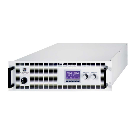
高效电源供应器系列
High Efficiency Power Supply Series
PSI 8000 3U
3.3kW - 15kW
40V - 1500V
30A - 510A
PSI 8080-170 3U:
09 230 430
PSI 8080-340 3U:
09 230 431
PSI 8080-510 3U:
09 230 432
PSI 8160-170 3U:
09 230 433
PSI 8240-170 3U:
09 230 434
PSI 8500-30 3U:
09 230 435
PSI 8500-60 3U:
09 230 436
PSI 8500-90 3U:
09 230 437
PSI 81000-30 3U:
09 230 438
PSI 81500-30 3U:
09 230 439
PSI 8200-70 3U:
09 230 440
PSI 8200-140 3U:
09 230 441
PSI 8200-210 3U:
09 230 442
PSI 8400-70 3U:
09 230 443
PSI 8600-70 3U:
09 230 444
PSI 8040-170 3U:
09 230 445
PSI 8040-340 3U:
09 230 446
PSI 8040-510 3U:
09 230 447
Advertisement
Chapters

Related Manuals for Elektro-Automatik High Efficiency Power Supply Series


Summary of Contents for Elektro-Automatik High Efficiency Power Supply Series
- Page 1 高效电源供应器系列 High Efficiency Power Supply Series PSI 8000 3U 3.3kW - 15kW 40V - 1500V 30A - 510A PSI 8080-170 3U: 09 230 430 PSI 81500-30 3U: 09 230 439 PSI 8080-340 3U: 09 230 431 PSI 8200-70 3U: 09 230 440...
- Page 3 一般信息 © Elektro-Automatik 安全须知 严禁再版、复印或部分错误地使用该说明书,否则将承担 • 请仅在铭板标示电压下操作该仪器。 该行为导致的法律后果。 • 请勿将任何机械零件,特别是金属件,插入仪器通风 孔内。 • 请避免在仪器周围使用液体物质,因有可能进入仪器 内部并损坏它。 • 不要将可能产生高于产品额定输出电压的设备连接到 本产品上。 • 在后板插槽上安装接口卡时,应遵循一般防静电规则。 • 接口卡只能在仪器完全关闭(电源开关关闭)后插入和 取出。 重要说明 • 产品老化以及超负荷使用都可能导致如按钮、旋转编译 器类的产品控制件操作不稳定。 PSI 8000 3U 日期: 05-03-2012 系列产品说明书...
-
Page 4: Table Of Contents
7. 产品设置 ....................23 7.1 定义操作参数 ..................24 7.2 预定义预设清单 ..................24 7.3 调节极限 ....................25 7.4 配置控制面板 ..................25 © 2006, Elektro-Automatik GmbH & Co. KG 7.5 配置图显 ....................26 Irrtümer und Änderungen vorbehalten 7.6 监控 ....................26 7.6.1 电压监控 ..................26 7.6.2 电流监控 .................. - Page 5 目录 页码 8. 下列情形发生时的反应..................30 8.1 用电源开关打开 ..................30 8.2 用电源开关关闭 ..................30 8.3 转至远程控制模式 ..................30 8.4 出现过压 ....................30 8.5 出现过温 ....................30 8.6 调整电压、电流和功率 .................. 30 8.7 远程感测被激活 ..................30 8.8 市电出现欠压或过压 ..................30 8.9 连接不同类型的负载 ..................31 9. 数字接口卡 ....................
-
Page 6: 技术规格
2ms to 9.999 s 范围1: 10ms to 59.99s 范围2: 1:00m to 59:59min 范围3: 1:00h to 99:59h 范围4: 精确度: 范围1: 10ms 范围2: © 2006, Elektro-Automatik GmbH & Co. KG 范围3: Irrtümer und Änderungen vorbehalten 1 min 范围4: PSI 8000 3U 日期: 05-03-2012 系列产品说明书... -
Page 7: 各型号详细规格
关于产品 2.2 各型号详细规格 PSI 8040-170 3U PSI 8080-170 3U PSI 8200-70 3U PSI 8500-30 3U PSI 8040-340 3U 电源输入 340…460V AC 340…460V AC 340…460V AC 340…460V AC 340…460V AC 输入电压范围 可选输入电压范围 L1, L2, PE L1, L2, PE L1, L2, PE L1, L2, PE L1, L2, L3, PE 要求相数... - Page 8 EN 61326, EN 55022 等级 A 过压等级 保护等级 污染程度 <2000m 工作高度 串联操作 600V 最大串联电压 无 主-从操作 © 2006, Elektro-Automatik GmbH & Co. KG 并联操作 Irrtümer und Änderungen vorbehalten 1500V 最大并联电压 有,经共享总线连接器 主-从操作 模拟编程 0…5V 或 0…10V,可选 输入范围 ≤ 0.2% 精确度* 53kOhm 输入阻抗...
- Page 9 关于产品 PSI 8500-60 3U PSI 81000-30 3U PSI 8080-510 3U PSI 8200-210 3U PSI 8240-170 3U 电源输入 340…460V AC 340…460V AC 340…460V AC 340…460V AC 340…460V AC 输入电压 588…796V AC +MP 588…796V AC +MP 588…796V AC +MP 可选输入电压范围 L1, L2, L3, PE L1, L2, L3, PE L1, L2, L3, PE L1, L2, L3, PE...
- Page 10 EN 61326, EN 55022 等级 A 过压等级 保护等级 污染程度 <2000m 工作高度 串联操作 600V 最大串联电压 无 主-从操作 并联操作 © 2006, Elektro-Automatik GmbH & Co. KG 1500V Irrtümer und Änderungen vorbehalten 最大并联电压 有,经共享总线连接器 主-从操作 模拟编程 0…5V 或 0…10V,可选 输入范围 ≤ 0.2% 精确度* 53kOhm 输入阻抗...
-
Page 11: 产品描述
关于产品 3. 产品描述 3.1 各面视图 PSI 8000 3U 日期: 05-03-2012 系列产品说明书... - Page 12 关于产品 © 2006, Elektro-Automatik GmbH & Co. KG Irrtümer und Änderungen vorbehalten PSI 8000 3U 日期: 05-03-2012 系列产品说明书...
- Page 13 关于产品 图 5 PSI 8000 3U 日期: 05-03-2012 系列产品说明书...
-
Page 14: 供应清单
5.1 目检 收到产品拆包装后,请检查是否有外观受损痕迹。如有,请不 要操作该产品,应立即联系您的供应商。 5.2 输入端连接(单机) 本系列产品的交流输入端必须连接两相(3.3kw/5kW型号)或 三相,(6.6kW/10kW/15kW型号)的产品则要求连接带接地 (PE)的三相供电电压。 该连接必须使用合适直径的连接线来完成。见下表举例,都针 对单机连接的连接线: ø ø ø 3.3kW 2,5mm² 2,5mm² © 2006, Elektro-Automatik GmbH & Co. KG 2,5mm² 2,5mm² Irrtümer und Änderungen vorbehalten 6.6kW 2,5mm² 2,5mm² 2,5mm² 10kW 4mm² 4mm² 4mm² 15kW 4mm² 4mm²... -
Page 15: 输入保险丝
关于产品 图6. 3.3kW/5kW产品输入端连接线图 图7. 6.6kW/10kW/15kW产品输入端连接线图 6.6kW/10kW型号的有所不同。比如,L2(S)处已负载一台28A 我们建议使用1,5m长的连线: 的产品,该情况下则建议更改相位图。意即,不必将L1(R)相 6mm² 16mm² 针对30A: 针对70A: 接到产品输入端子的L1输入极。下图显示了一个电流几乎对 25mm² 50mm² 针对90A: 针对140A: 称分布的范例,其中L1 = max. 44A, L2 = max. 56A 以及 L3 = max. 60A。 针对170A: 70mm² 95mm² 针对210A: 下图以6.6kW/10kW型号产品的配置为例: 针对340A: 2x70mm² 2x120mm² 针对510A: 上面每个直流输出端连线的最小直径(软性线)。 例如70mm²的单线,也可用2条35mm²的连线代替。... -
Page 16: 输出端接地
总线模式下的并联“。 5.7 “Sense”(远程感测)端 注意!不可将不同于 3U 系列的产品连接到共享总线端上,即使 了补偿负载线上的压降,电源可“感测”负载上的电压,而不 它也有共享总线连接功能。 是输出端的电压。它将调整输出电压,以便能提供所需电压给 负载。最大调整值可见章节„2.2 各型号详细规格“下的“远 5.9 接口卡插槽 程感测补偿”。 本系列产品可配一接口卡。接口卡插槽位于产品后面。关于卡的 远程感测的连接点在产品后板“感测”端子上。也可见章节 详细信息请参考接口卡用户使用指南中章节„9. 数字接口卡“, 3.1。 以及接口卡快速安装指南。 (+)感测端只能与负载设备的(+)输出端相连,(–)感测端与 (–)输出端相连!否则会损坏本产品。 面板其它信息请见章节8.7。 © 2006, Elektro-Automatik GmbH & Co. KG Irrtümer und Änderungen vorbehalten PSI 8000 3U 日期: 05-03-2012 系列产品说明书... -
Page 17: 使用符号
关于电源 6. 操作 设定电流 6.1 显示 期望输出电流的目标值(右旋钮)。可对该值粗调(见章节 图8展示了图形显示器的总图。正常操作时,显示器显示实际和 6.6的步宽)或细调(逗号最右边数位)。粗调和细调见得转 设定电压(左上排)和电流(右上排),以及功率(左下排)。 换通过右旋转编译器上的按钮完成。要调节设定值必须先按 而在设置模式下,显示参数和相关设置。 按钮。 如果“内阻控制”解锁,内阻设定值可能代替功率设定值,随 产品设置所选而定。 6.2 使用符号 设定功率 下列描述的显示和操作元素以不同符号标示。 期望最大输出功率的目标值(右旋钮)。要设定该值,必须在 之前就按下 按钮。该数值可粗调(见章节6.6的步宽) ,也可细调(逗号最右边数位)。 = 仅显示,所有只显示,代表状态的元素以这个符号标识 = 参数,可更改值以该符号标识,且表示强调 = 菜单项目,可选择,指向下个分级或带参数的最低级 设定内阻(选项) {…}括号表示可能的选项或参数的调节范围。 期望内阻的目标值(右旋钮)。如果内阻控制解锁,且在产品 设置下选择了U/I/R模式,该设定值替代功率设定值。要设定该 6.3 各显示元素简介 值,必须先按下... -
Page 18: 打开功率输出
210A 0.1A 直接设置设定值 500V 0.1V 340A 0.1A 600V 0.1V 510A 0.1A 用旋钮可直接设置设定值。 1000V 左旋钮调电压。当电压设定值被选定并调整时,数字反过来显 © 2006, Elektro-Automatik GmbH & Co. KG 1500V 示。 Irrtümer und Änderungen vorbehalten 右旋钮既可以设置电流、功率设定值,也可以设置内阻设定值 功率 (当选择了模式,且该模式已解锁)。选定的设定值反向显示 额定值 粗调 细调 于屏幕上。 3.3/5kW 0.050kW 0.001kW 6.6/10kW 0.10kW 0.01kW 15kW 0.10kW 0.01kW... -
Page 19: 转换按钮面板
使用电源 6.7 转换按钮面板 6.12 参数页 参数页为菜单最底级。在这您可更改多种不同参数来设置产品。 PAGE 按钮可转换至另一按钮面板。用户利用其他面 板的新按钮锁定控制面板,转至函数管理器或设置位置模式。 按ESC键进入参数页的上级菜单,不再接受任何参数。 6.8 锁定控制面板 用SELECT 键选择不同参数。所选参数会反向 显示,用左旋钮可进行更改。 “锁定按钮面板”按钮可锁住所有除它自身和旋钮外的 任何其它键。这样产品被锁定后,不可手动进入,不能更改任 RETURN键将更改后并被接受和保存的参数提交出去。 何参数,也不可进入任何菜单。在菜单下可设定锁定模式。于 并退出参数页面,进入下一个上级菜单。 是可使控制面板完全失效,或者用OFF键解除(产品被锁定但 可通过OFF键打开和关闭)。可参考章节„7.4 配置控制面板“ 6.13 报警、警告和信号提示 的“键盘锁定”。 报警,警告和简单提示(此被称作“信号提示”)以声音或可 视信号发出。内置模拟接口或可选模拟接口卡IF-A1的“OT” 控制面板锁定后,图标即变为这个。此按钮可用于再次 或“OVP”引脚也报告过压或过温错误。也可见章节„7.4 配置 解除控制面板的锁定,如果 控制面板“。 报警要优先于警告或信号提示。一次可显示多至四种报警,警 按住此键2s。 告或信号提示,且以每两秒间隔时间循环一次。如显示的信号 超过四个,再有报警出现,前面的警告或提示信号将被取消, 6.9 更改定位模式 用报警替代。 用EXT按钮,用户通过数字或模拟接口卡可启动远程控... -
Page 20: 函数管理器
I> def. def. def. 超过过流监控阀值 I< def. def. def. 超过欠流监控阀值 U def. def. def. 正向电压转换时设定值比较出错 © 2006, Elektro-Automatik GmbH & Co. KG U def. def. def. 负向电压转换时设定值比较出错 Irrtümer und Änderungen vorbehalten I def. def. def. 正向电流转换时设定值比较出错 I def. def. def. -
Page 21: 配置序列
使用电源 6.15.3 配置序列 6.15.5 函数运行时的显示 Sequence {1..5}指向序列编辑页。 菜单页 Sequence points 0-4 {5-9} + 一个序列由10个序列点组成。一个序列点由3组数据组成: 电 Sequence {1..5} + 压U, 电流I和时间∆t的设定值。 指向下列菜单选项: ∆t = { 0…99:59h} Sequence {1..5} (要编辑的序列数) U[ V] = { 0… U ... -
Page 22: 函数运行时的显示
函数发生器启动后的累计时间也会显示出 来。函数管理器停止,时间显示才停止。STEP,RUN或GO 键以多种方式操作函数管理器,同时时间显示会持续累计。 {ON,OFF} 电源输出状态 除电源输出状态外,还显示报警,警告或信号提示状态。 用GO键继续运行停止后的函数。 6.15.7 函数管理器的控制 或者用NEW键可重设函数管理器,开始执行当前函 交互式控制面板给函数管理器提供多个控制键。利用这些按键用 数。 户可暂停、继续、重设为起始点或退出函数管理器。. 函数管理器真正设定电源前,可在显示屏幕上模拟此函数。在 此操作过程中 - 不可打开输出,且 - 一步一步处理这些序列点,并按相同方法检验。 © 2006, Elektro-Automatik GmbH & Co. KG Irrtümer und Änderungen vorbehalten 也可通过接口卡执行此操作。还可在50个序列点中额外地设置 一停顿点。处理到这个点时,序列、函数就会暂停。 PSI 8000 3U 日期: 05-03-2012 系列产品说明书... -
Page 23: 产品设置
使用电源 7. 产品设置 Profile菜单 第1部分: 此为参数页全图。彩色菜单或参数可能不 会出现在每个型号上,跟选项有关。 Profile + 该配置文件意在减少不同用户设置产品时所需时间,或保留用 户定义的设定参数,以便将来重复使用。最后使用的配置文件 Supervision + 总在电源启动后上载。 Supervision Profile菜单将出现下列选项: 进入 菜单,指向下列选项,可对报警、警告和 进入 信号提示,还有相应监控限制和反应时间进行设置。 General settings U thresholds Supervision I thresholds Load profile Step response ... -
Page 24: 定义操作参数
10.00 10.00 1.200 0.00 0.00 1.500 0.00 0.00 1.500 * 阻值(红色)仅在U/I/R模式解锁的情况下出现。 Accept set value = from preset list 利用参数 您可从正常 设定值转换到其中一组预设值,或在两组预设值之间转换。通 过此选项实际上可在设定值之间“跳跃”。 © 2006, Elektro-Automatik GmbH & Co. KG Irrtümer und Änderungen vorbehalten PSI 8000 3U 日期: 05-03-2012 系列产品说明书... -
Page 25: 调节极限
使用电源 7.3 调节极限 功率设定值极限 P adj max 默认:P nenn Adjust limits + = { 0 kW… P nenn 在此可定义最大和最小调整极限。这些极限常常在本地或远程 在此可定义可调功率的上限和下限。超出极限的设定值不被接 模式(即:产品由电脑控制)下受干扰。 受,不管是由控制板还是电脑控远程控制(通过接口卡通讯)产 生。 电压设定值极限 内阻设定值极限 U adj 默认:0V, U nenn (可选项,仅在U/I/R模式解锁情况下) = {U } {U adj.min adj.max ... -
Page 26: 配置图显
Tu> 默认:100 ms = { 0…99:59h} 这与OVP(见上述)有稍微不同。在这也监控电压,但过了定义的 Tu>时间后,以报警,警告或信号提示告知用户。如果 延时 Tu>时间内电压下降至极限以下,该信号消失。因此您不 在 Tu> 是每次收到OVP错误信息,或者过压出现时间大于定义 时间时只听到报警声,也可监控过压。 © 2006, Elektro-Automatik GmbH & Co. KG Irrtümer und Änderungen vorbehalten U> 报警: 过压 此错误关断电源输出。必须确认报警错误后,才能再次打开输 出。 U> 警告:过压 此错误出现后并持续存在,直到信息被确认方才消失。 U> 信号提示:过压... -
Page 27: 电流监控
使用电源 7.6.2 电流监控 欠压监控 I thresholds + thresholds配置欠流和过流监控电路。 菜单页 欠流监控 U< 默认:0V = { 0… U>} Tu< 默认:100ms = { 0…99:59h} I< 默认:0A Tu<后,发出欠 电压一下降至欠压极限以下,过了响应时间 = { 0… I>} Tu<内超过欠压极限,信号消失。在电源输 压信号。如果在 Ti< 默认:100ms =100ms。... -
Page 28: 阶跃响应监控
Tsr = {0…99:59h} 默认:100ms I> 报警:过流 此错误关断电源输出。必须确认报警信息后,才能再次打开电 fall time 源输出。 Tsf = {0…99:59h} 默认:2s} I> 警告:过流 此错误出现后并持续,直到信息被确认后才消失。 I> 信号提示:过流 模拟接口(IF-A1,可选)可从其中一数字输出端发出过流或欠流 信号。 © 2006, Elektro-Automatik GmbH & Co. KG Irrtümer und Änderungen vorbehalten PSI 8000 3U 日期: 05-03-2012 系列产品说明书... -
Page 29: 恢复至默认配置
使用电源 7.8 解锁U/I/R运行模式 设定/真实值比较的通知 Tsr内未完成较低设定值到较高设定 R mode available: 例如:如果在设定时间 值的跳跃,就会发出报警、警告或信号提示类的监控错误。 U/I/R操作模式锁定已解除并可用 U/I/R操作模式还不可用 或 或 U/I/R运行模式只有用PIN码解锁后才可用。并在配置文件中进 行配置。(见„7.1 定义操作参数“) Step response的配置,选择I 根据 状态发出通知。 解锁U/I/R运行模式的识别码要另外购买。如果您有意使用此模 式,在订购该产品时一起购买,也可以后再订购。 Tsf内未完成较低设定值到较高设定 例如:如果在设定时间 值的跳跃,就会发出报警、警告或信号提示类的监控错误。 Enable R mode + ... -
Page 30: 下列情形发生时的反应
升输出电压。 以“OV”状态文本信息,内置模拟接口的“OVP”引脚14, 最大补偿电压:见规格参数表,不同型号会有不同。 模拟接口IF-A1(如果配有的话)的“OVP”引脚8,以及报警 也可见下页图10。 符号指示此错误。 应避免加载于输出端的外部电压超过额定电压的120%,否则产 8.8 市电出现欠压或过压 品内部元件会受损! 本产品需用到一400V相线电压的三相电源,其电压误差最大为 如果过压原因消除,输出会再次打开,“OV”状态文本信息 +15%。从而形成340V...460V输入电压范围。在该范围内,产 消失。在此之前,需用 按钮或经数字接口的一个指令确 品操作无功率限制。340V AC以下的输入电压被视为欠压,将 认该报警信号。如果错误仍然存在,则不打开输出。 保存最后状态,并关闭输出。如电压超过460V AC,结果一样。 OVP错误以报警声记录于内部警报缓冲区。通过数字接口可读 应避免输入端长期欠压或过压! © 2006, Elektro-Automatik GmbH & Co. KG 取该缓冲区内容。用另一指令可清楚缓冲区内容。 Irrtümer und Änderungen vorbehalten PSI 8000 3U 日期: 05-03-2012 系列产品说明书... -
Page 31: 连接不同类型的负载
操作产品 8.9 连接不同类型的负载 9.2 配置接口卡 不同类型的负载,如阻性负载(台灯,电阻),电子负载或感性 Communication 接口卡必须被配置一次。通过菜单 完成。 负载(马达),性能不同,它们会对电源起反作用。例如,马达 会产生一反电压,导致电源因过压保护而关断输出。 Communication + 电子负载有电压、电流和功率调整线路,它们与电源的相互作 用,可能会提高输出纹波或其它多余的副作用。电阻负载几乎 100%中性。故建议在安排应用时要考虑负载的特性。 Device node 默认:1 9. 数字接口卡 = {1..30} 总共可给一台产品配置30个设备结点(地址)。 如果是控制多台产品,也只需设置一次设备节 9.1 一般信息 点。 该电源支持多种通讯或模拟控制用接口卡。除Profibus卡IF-PB1 除 模 拟 接 口 卡 外 , 使 用 其 它 接 口 卡 时 必 须 设 置 产 品 地 址 外,所有卡都耐压2000V。Profibus卡耐压1000V。... -
Page 32: 模拟接口
的负输出端,如果连上,就表示控制设备连到了电源输 • 连接控制电源的应用设备前,要保证所有线连接正确,并检查 出负极(形成接地回路),负载电流流经控制线,从而 应用设备不会输入高于指定电压的电压(最大12V)。 损坏设备! • REM-SB(远程待机,13引脚)引脚要优先于On按钮。意思 是,如果该引脚定义输出状态为“off”,就不能用该按钮打 开输出。故它可当紧急断电开关用。但不适用于控制位置设 为local的情况。详情页可参考章节6.9。 • VREF输出引脚给设定值输入脚VSEL、CSEL和PSEL创建设 定值,如仅需电流控制,可将VSEL和PSEL脚连到VREF脚, 然后通过一外电压(0...5V或0...10V)来供电,或通过VREF与 地间的电位器来给CSEL供电。也可参考下一章节。 • 输入高于设置菜单下规定的数值会限制在100%以内。低于规 定值也一样,则会被限制到0%。 • 模拟接口的地与输出负极相连。 图 11 © 2006, Elektro-Automatik GmbH & Co. KG Irrtümer und Änderungen vorbehalten 图 12 PSI 8000 3U 日期: 05-03-2012 系列产品说明书... -
Page 33: 产品设置下的设定
操作产品 10.3 产品设置下的设定 10.4 应用举例 输出关闭 “REM-SB”引脚13一直都为工作状态,因此它不依附于远程 模式。故在不利用外部手段的条件下用它可关闭输出,除非产 Analogue interface + 品已设为local模式,于是该引脚不起任何作用。用一低阻连 设置菜单允许对内置模拟接口设定参数的访问: 接片,如开关、开集三极管或继电器,将该引脚与地(DGND) 相连,即可关闭输出,如果REM-SB引脚(见章节10.3)选 择“LOW”设定。若设为“HIGH”,则刚好相反,且连接片 要打开,以便关不输出(紧急关闭原则)。 注意:PLC的数字输出脚可能无法正确执行其功能,也许是因 为连接片阻值不够低。故需检查外部控制设备的技术参数再选 择合适的阻值。 图形解释: 远程控制电流和电压 Analogue voltage 默认:0...10V 注意:经模拟接口的远程控制一定要输入所有三组设定值。 = { 0...5V | 0...10V } 为模拟输入和输出引脚选择电压范围, VREF与接地脚之间有两电位器,VSEL与CSEL输入脚间有一 它对应0...100%的设定/实际值定 滑动器。功率设定值引脚PSEL与VREF相连,故可设为100% 。利用前板上的旋钮可控制本电源,将它当作电流源或电压 REMOTE /5 默认:LOW 源用。如果VREF输出脚的电流最大为5mA,则需使用至少为... -
Page 34: 模拟接口各引脚分布
CC = HIGH, U >4V 短路保护对DGND high * AI = 模拟输入脚,AO =模拟输出脚,DI = 数字输入脚,DO = 数字输出脚,POT =电位脚 ** 内部 Vcc = 13.8V *** 默认设定,可在菜单设置下更改 © 2006, Elektro-Automatik GmbH & Co. KG Irrtümer und Änderungen vorbehalten PSI 8000 3U 日期: 05-03-2012 系列产品说明书... -
Page 35: 其它应用
操作产品 11. 其它应用 11.3 其它附件和选项功能 可供下列附件: 11.1 共享总线模式下的并联 a) 数字接口卡 共享总线操作为了使并联下运行的多台设备获得均衡的负载电 还配USB,RS232,CAN,GPIB/IEEE (仅SCPI) 或以太网/ 流。 LAN (仅SCPI )或Profibus用可插拔式数字接口卡。每款产品型 重点:在该操作模式下,输出电压最高的产品控制并决定整个 号都有一个接口卡插槽。 并联连接下产品的输出电压。意思是,系统内的任何产品都可 b) 扩展模拟接口卡 能但当此角色。故建议选择某一台机来控制整个系统的同时, 还配可插拔式、电隔离、25针模拟接口卡。关于详细介绍,请 要将其余机台的设定电压设为需求最小值。电压和功率设定值 参考接口卡说明书. 也可设为100%。若不用这样,对每台机设定平均值,这样方 可获得所需总值。 若有一台机坏掉,会终止运作。而并联连接上的其他产品则继 可供下列选项: 续工作,且无间断。这就是冗余操作。 a) High Speed Ramping 若产品出现错误,如过温(OT)或过压,输出电压会上升或下 通过减少输出电容容量来增加输出电压的动态。必须指出的是 降至剩余产品中电压最高的值。 其它相关输出值也增加! 共享总线操作“Share”端子的连线方式在„5.8 “Share”(共 注意:这是个永久性更改,不可更改回来。 享)端“章节内有详细解释。也可参考下页图13。... - Page 36 操作产品 图 13. Share Bus- 共享总线并联连线图 © 2006, Elektro-Automatik GmbH & Co. KG Irrtümer und Änderungen vorbehalten 图 14. 串联连线图 PSI 8000 3U 日期: 05-03-2012 系列产品说明书...
-
Page 37: 固件更新
操作产品 11.4 连网 11.5 固件更新 下图描述了多台产品在数控状态下以星形(USB,RS232 只有当产品出现错误行为或者应用新功能时才需进行产品固件 ,Ethernet)或车形(CAN,GPIB,Profibus)配置的连网举 更新。 例。 要更新一台产品固件,需要用到某一数字接口卡,新的固件文 适用总线系统和接口的限制和技术规格。 档,称作“更新工具”的Windows软件。 通过USB,一台电脑可控制多达30台产品,需使用带特制电 下列这些接口卡才能用于固件更新: 源的USB集线器。这也基本适用于RS232。区别在于操作和 • IF-U1 (USB) 线长。 • IF-R1 (RS232) 通过CAN,每个地址段上的多达30台电源,可容入新的或现有 • IF-E1 (Ethernet/USB) 的CAN总线系统。它们由产品节点和RID(见„7. 产品设置“) 组成。 • IF-PB1 (Profibus/USB) 通过GPIB,每一条总线限制最多为15台,由一台GPIB主机控 如果手上没有一张上述接口卡,则不可更新。请立即联系您的 制。一台电脑上可安装多台主机,这样可增加可编址单元数。 产品销售方寻求解决方案。 产品对应的更新工具和固件文档可从产品制造商网站获取,或 者发邮件索取。更新工具将会指导用户整个半自动更新过程。 图15. 通过USB或RS232连网 图16. - Page 39 General © Elektro-Automatik Safety instructions Reprint, duplication or partly, wrong use of this user instruction • Only operate the device at a mains voltage as stipulated on manual are prohibited and might be followed by legal conse- the type plate! quences.
- Page 40 7. Device configuration ................................60 Defining operation parameters ............................61 Predefining preset lists ..............................61 Adjustment limits ................................62 Configuring the control panel............................62 © 2006, Elektro-Automatik GmbH & Co. KG Configuring the graphic display ............................63 Irrtümer und Änderungen vorbehalten Supervision ..................................63 7.6.1 Voltage supervision..............................63 7.6.2...
- Page 41 Table of contents Page 8. Behaviour of the device when..............................67 Switching on by power switch............................67 Switching off by power switch ............................67 Switching to remote control .............................67 Overvoltage occurs................................67 Overtemperature occurs ..............................67 Voltage, current and power are regulated ........................67 Remote sense is active ..............................68 Mains undervoltage or overvoltage occurs ........................68 Connecting different types of loads ..........................68 9.
-
Page 42: Introduction
Range 3: 1:00m to 59:59min Range 4: 1:00h to 99:59h Accuracy: Range 1: Range 2: 10ms © 2006, Elektro-Automatik GmbH & Co. KG Range 3: Irrtümer und Änderungen vorbehalten Range 4: 1 min Instruction Manual Date: 05-03-2012 PSI 8000 3U Series... -
Page 43: Device Specifications
About the device Device specifications PSI 8040-170 3U PSI 8080-170 3U PSI 8200-70 3U PSI 8500-30 3U PSI 8040-340 3U Mains input Input voltage range 340…460V AC 340…460V AC 340…460V AC 340…460V AC 340…460V AC Input voltage range optional Required phases L1, L2, PE L1, L2, PE L1, L2, PE... - Page 44 Pollution degree <2000m Operational altitude Series operation max. series connection voltage 600V Master-Slave Parallel operation © 2006, Elektro-Automatik GmbH & Co. KG Irrtümer und Änderungen vorbehalten 1500V max. parallel connection voltage yes, via Share bus Master-Slave Analogue programming Input range 0…5V or 0…10V, selectable...
- Page 45 About the device PSI 8500-60 3U PSI 81000-30 3U PSI 8080-510 3U PSI 8200-210 3U PSI 8240-170 3U Mains input Input voltage range 340…460V AC 340…460V AC 340…460V AC 340…460V AC 340…460V AC Input voltage range optional 588…796V AC +MP 588…796V AC +MP 588…796V AC +MP Required phases L1, L2, L3, PE L1, L2, L3, PE...
- Page 46 Pollution degree <2000m Operational altitude Series operation max. series connection voltage 600V Master-Slave Parallel operation © 2006, Elektro-Automatik GmbH & Co. KG Irrtümer und Änderungen vorbehalten 1500V max. parallel connection voltage yes, via Share bus Master-Slave Analogue programming Input range 0…5V or 0…10V, selectable...
-
Page 47: Device Description
About the device Device description Views Instruction Manual Date: 05-03-2012 PSI 8000 3U Series... - Page 48 About the device © 2006, Elektro-Automatik GmbH & Co. KG Irrtümer und Änderungen vorbehalten Instruction Manual Date: 05-03-2012 PSI 8000 3U Series...
- Page 49 About the device Figure 5 Instruction Manual Date: 05-03-2012 PSI 8000 3U Series...
-
Page 50: Scope Of Delivery
Input connection (single unit) The unit‘s AC input requires two (3.3kw/5kW models) or three phases (6.6kW/10kW/15kW) models of a three-phase supply, © 2006, Elektro-Automatik GmbH & Co. KG plus ground (PE). Irrtümer und Änderungen vorbehalten The connection is done with cables of proper cross section. -
Page 51: Input Fuses
About the device Figure 6. Input connection 3.3kW/5kW Figure 7. Input connection 6.6kW/10kW/15kW The 6.6kW/10kW models are different. Phase L2(S) is here Up to 1.5m cable length we recommend to use: loaded with 28A by already one unit. In this case it is recom- up to 30A: 6mm²... -
Page 52: Grounding The Output
(+) Sense must only be connected to (+) at the load appli- cation and (–) Sense must only be connected to (–)! Else both systems can take damage. For additional information also see section 8.7. © 2006, Elektro-Automatik GmbH & Co. KG Irrtümer und Änderungen vorbehalten Instruction Manual Date: 05-03-2012... -
Page 53: Handling
About the power supply Handling Set value of voltage The display Target value of the desired output voltage (left knob). The value Figure 8 below shows an overview of the graphical display. is adjusted in coarse (see section 6.6 for step widths) or fine During normal operation, the display shows the actual and set (always rightmost digit). -
Page 54: Switching The Power Output On
The resistance set value is adjustable from 0Ω up to that the output will switch on as soon as the override from the © 2006, Elektro-Automatik GmbH & Co. KG 20* Unom/Inom. Means, for example, at a device with Unom pin is removed. -
Page 55: Step Widths For Set Value Adjustment
Using the power supply Using predefined set values Changing the location mode A table of up to 4 sets of set values is accessible in the menu With the button the user enables the remote control Preset List (see „7.2 Predefining preset lists“). The left knob of the unit via a digital or analogue interface card and deactivates selects the preset list and with the RETURN... -
Page 56: Parameter
U Set-actual comparison error at a positive voltage transition def. def. def. U © 2006, Elektro-Automatik GmbH & Co. KG def. def. def. Set-actual comparison error at a negative voltage transition Irrtümer und Änderungen vorbehalten I def. def. def. -
Page 57: The Function Manager
Using the power supply 6.15 The function manager Sequence point = a sequence always consists of 10 sequence points. The points are processed (=set) consecutively by the The function manager is used to create functions which can function manager from point 0 to point 9. The definition of the control the unit automatedly. -
Page 58: The Function Layout
= {1..254} it will be repeated n times Function manager is running = ∞ it will be repeated infinitely © 2006, Elektro-Automatik GmbH & Co. KG 15:05 m Irrtümer und Änderungen vorbehalten The elapsed time since the function gene- P seq= {0…P... -
Page 59: Controlling The Function Manager
Using the power supply 6.15.7 Controlling the function manager The interactive control panel provides keys to control the func- Use the button to continue the function after it tion manager. You can halt, continue, reset it to the starting point was stopped. -
Page 60: Device Configuration
Save profile Load profile + General settings + © 2006, Elektro-Automatik GmbH & Co. KG Load profile from user profile = {default, 1..4} The menu entry General settings leads to following se- Irrtümer und Änderungen vorbehalten The current profil is replaced by the selected one. -
Page 61: Defining Operation Parameters
Using the power supply Defining operation parameters This is shown in the display while the internal resi- -stance control is active and U/I/R operation is set. Setup operation mode + The internal resistance Ri is displayed instead of the power while U/I/R mode is active. -
Page 62: Adjustment Limits
= enable The rotary knobs and most buttons will be locked © 2006, Elektro-Automatik GmbH & Co. KG = disable No lock Irrtümer und Änderungen vorbehalten The control panel lock is used to prevent from unwanted changes to the set values or to the settings. -
Page 63: Configuring The Graphic Display
Using the power supply Sounds Supervision Key sound Default: Supervision + = YES A short beep signalises a button press Supervision menu lets you configure the supervision of = NO No signal if keys are pressed output voltage, output current and output power. You can also ... -
Page 64: Current Supervision
=100ms after the Tu< Default: 100ms power output was switched on. © 2006, Elektro-Automatik GmbH & Co. KG = { 0…99:59h} Irrtümer und Änderungen vorbehalten I< Alarm: Undercurrent As soon as the voltage falls below the undervoltage threshold, This error shuts down the power output. -
Page 65: Step Response Supervision
Using the power supply Overcurrent supervision 7.6.3 Step response supervision Step response + The menu page Step response lets you configure the supervision circuits for the dynamic and static comparison of actual value and set value. Step response Default: Us→Uo Us→Uo... -
Page 66: Reset To Default Configuration
Reset configuration + Are you sure ? Default: = YES All modifications of the default setup are reset = NO No change © 2006, Elektro-Automatik GmbH & Co. KG Irrtümer und Änderungen vorbehalten Instruction Manual Date: 05-03-2012 PSI 8000 3U Series... -
Page 67: Behaviour Of The Device When
Using the power supply Behaviour of the device when... Overvoltage occurs An overvoltage error can occur due to an internal defect (out- Switching on by power switch put voltage rises uncontrolledly) or by a too high voltage from external.The overvoltage protection (OVP) will switch off the The power switch is located at the front. -
Page 68: Remote Sense Is Active
Same happens at overvoltage above 460V AC. Permanent input undervoltage or overvoltage must be avoided! © 2006, Elektro-Automatik GmbH & Co. KG Irrtümer und Änderungen vorbehalten Figure 10. Wiring remote sense Instruction Manual... -
Page 69: Digital Interfaces
Operating the device Digital interfaces 10. Analogue interface General 10.1 General The power supply supports various interface cards for commu- The integrated, 15 pole analogue interface is located on the nication or analogue control. All cards, except Profibus card front and offers, amongst others, following possibilities: IF-PB1, are galvanically isolated up to 2000V. -
Page 70: Settings In The Device Setup
LOW or HIGH level. For the levels of LOW Figure 12 and HIGH see section 10.4. © 2006, Elektro-Automatik GmbH & Co. KG Irrtümer und Änderungen vorbehalten Instruction Manual Date: 05-03-2012 PSI 8000 3U Series... -
Page 71: Pin Specifications
Operating the device 10.4 Pin specifications Pin Name Type* Description Level Electrical specification 0…10V or 0...5V correspond VSEL Set value: voltage to 0..100% of U Accuracy < 0.2% Impedance R >100k 0…10V or 0...5V correspond CSEL Set value: current to 0..100% of I Accuracy <... -
Page 72: Miscellaneous
600V. Looking at the resulting potentials on the negative © 2006, Elektro-Automatik GmbH & Co. KG outputs of the units, the 3rd unit negative DC pole could be Irrtümer und Änderungen vorbehalten... - Page 73 Operating the device Figure 13. Parallel connection with Share Bus Figure 14. Series connection Instruction Manual Date: 05-03-2012 PSI 8000 3U Series...
-
Page 74: Accessories And Options
The update tool and the particular firmware file for your device are obtainable from the website of the device manufacturer, or © 2006, Elektro-Automatik GmbH & Co. KG Irrtümer und Änderungen vorbehalten are mailed upod request. The update too will guide the user through the semi-automatic update process.
Need help?
Do you have a question about the High Efficiency Power Supply Series and is the answer not in the manual?
Questions and answers