
Subscribe to Our Youtube Channel
Related Manuals for Elektro-Automatik PSI 9040-20 T


Summary of Contents for Elektro-Automatik PSI 9040-20 T
- Page 1 Operating Guide PSI 9000 T DC Laboratory Power Supply Doc ID: PSI9TEN Revision: 01 Date: 05/2017...
-
Page 3: Table Of Contents
Series connection ........70 2.3.10 Commission after a firmware update or a 3.11.2 Parallel operation .........70 long period of non-use .........34 3.11.3 Operation as battery charger .......70 EA Elektro-Automatik GmbH Fon: +49 2162 / 3785-0 www.elektroautomatik.de Page 3 Helmholtzstr. 31-33 • 41747 Viersen Fax: +49 2162 / 16230 ea1974@elektroautomatik.de... - Page 4 Preface ............72 4.3.2 Preparation ...........72 4.3.3 Calibration procedure ........72 CONTACT AND SUPPORT Repairs ............74 Contact options ..........74 EA Elektro-Automatik GmbH Fon: +49 2162 / 3785-0 www.elektroautomatik.de Page 4 Helmholtzstr. 31-33 • 41747 Viersen Fax: +49 2162 / 16230 ea1974@elektroautomatik.de Germany...
-
Page 5: General
EA Elektro-Automatik guarantees the functional competence of the applied technology and the stated performance parameters. The warranty period begins with the delivery of free from defects equipment. Terms of guarantee are included in the general terms and conditions (TOS) of EA Elektro-Automatik. Limitation of liability All statements and instructions in this manual are based on current norms and regulations, up-to-date technology and our long term knowledge and experience. -
Page 6: Disposal Of Equipment
• Claims of any sort due to damage caused by non-intended usage will not be accepted. • All damage caused by non-intended usage is solely the responsibility of the operator. EA Elektro-Automatik GmbH Fon: +49 2162 / 3785-0 www.elektroautomatik.de Page 6 Helmholtzstr. -
Page 7: Safety
• before starting work must have read and understood the operating manual • must use the designated and recommended safety equipment. Furthermore, anyone working with the equipment is responsible for ensuring that the device is at all times techni- cally fit for use. EA Elektro-Automatik GmbH Fon: +49 2162 / 3785-0 www.elektroautomatik.de Page 7 Helmholtzstr. -
Page 8: Responsibility Of The Operator
Delegated persons are those who have been properly and demonstrably instructed in their tasks and the atten- dant dangers. Qualified persons are those who are able through training, knowledge and experience as well as knowledge of the specific details to carry out all the required tasks, identify dangers and avoid personal and other risks. EA Elektro-Automatik GmbH Fon: +49 2162 / 3785-0 www.elektroautomatik.de Page 8 Helmholtzstr. -
Page 9: Alarm Signals
Colour TFT touch screen with gorilla glass, 3.5”, 320pt x 240pt, capacitive Controls: 2 rotary knobs with pushbutton functions, 2 pushbutton The nominal values for the device determine the maximum adjustable ranges. EA Elektro-Automatik GmbH Fon: +49 2162 / 3785-0 www.elektroautomatik.de Page 9 Helmholtzstr. -
Page 10: Specific Technical Data
PSI 9000 T Series 1.8.3 Specific technical data Model 320 W PSI 9040-20 T PSI 9080-10 T PSI 9200-04 T AC Input Voltage range 90...264 V AC 90...264 V AC 90...264 V AC Connection 1ph,N,PE 1ph,N,PE 1ph,N,PE Frequency 45-65 Hz... - Page 11 PSI 9000 T Series Model 320 W PSI 9040-20 T PSI 9080-10 T PSI 9200-04 T Power regulation Display: Resolution See section „1.9.5.4. Resolution of the displayed values“ Display: Accuracy ≤ 0.8% P ≤ 0.8% P ≤ 0.8% P Efficiency ~ 92% ~ 92% ~ 93%...
- Page 12 4.92 V and 5.08 V. (2 RMS value: LF 0...300 kHz, PP value: HF 0...20MHz (3 The display error adds to the error of the related actual value on the DC output EA Elektro-Automatik GmbH Fon: +49 2162 / 3785-0 www.elektroautomatik.de Page 12 Helmholtzstr.
- Page 13 (2 The display error adds to the error of the related actual value on the DC output (3 For technical specifications of the analog interface see „3.5.4.4 Analog interface specification“ on page 52 (4 Typical value at 100% output voltage and 100% power EA Elektro-Automatik GmbH Fon: +49 2162 / 3785-0 www.elektroautomatik.de Page 13 Helmholtzstr.
- Page 14 4.92 V and 5.08 V. (2 RMS value: LF 0...300 kHz, PP value: HF 0...20MHz (3 The display error adds to the error of the related actual value on the DC output EA Elektro-Automatik GmbH Fon: +49 2162 / 3785-0 www.elektroautomatik.de Page 14 Helmholtzstr.
- Page 15 (2 The display error adds to the error of the related actual value on the DC output (3 For technical specifications of the analog interface see „3.5.4.4 Analog interface specification“ on page 52 (4 Typical value at 100% output voltage and 100% power EA Elektro-Automatik GmbH Fon: +49 2162 / 3785-0 www.elektroautomatik.de Page 15 Helmholtzstr.
- Page 16 4.92 V and 5.08 V. (2 RMS value: LF 0...300 kHz, PP value: HF 0...20MHz (3 The display error adds to the error of the related actual value on the DC output EA Elektro-Automatik GmbH Fon: +49 2162 / 3785-0 www.elektroautomatik.de Page 16 Helmholtzstr.
- Page 17 (2 The display error adds to the error of the related actual value on the DC output (3 For technical specifications of the analog interface see „3.5.4.4 Analog interface specification“ on page 52 (4 Typical value at 100% output voltage and 100% power EA Elektro-Automatik GmbH Fon: +49 2162 / 3785-0 www.elektroautomatik.de Page 17 Helmholtzstr.
- Page 18 4.92 V and 5.08 V. (2 RMS value: LF 0...300 kHz, PP value: HF 0...20MHz (3 The display error adds to the error of the related actual value on the DC output EA Elektro-Automatik GmbH Fon: +49 2162 / 3785-0 www.elektroautomatik.de Page 18 Helmholtzstr.
- Page 19 (2 The display error adds to the error of the related actual value on the DC output (3 For technical specifications of the analog interface see „3.5.4.4 Analog interface specification“ on page 52 (4 Typical value at 100% output voltage and 100% power EA Elektro-Automatik GmbH Fon: +49 2162 / 3785-0 www.elektroautomatik.de Page 19 Helmholtzstr.
-
Page 20: Views
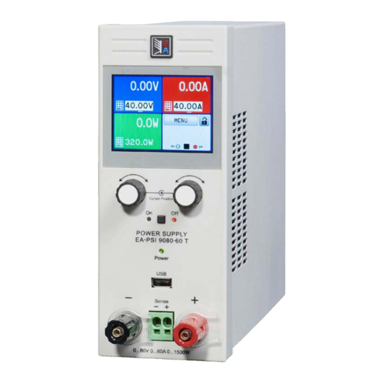
B - Knobs C - USB port D - DC output E - Remote sensing connector Figure 1 - Front view EA Elektro-Automatik GmbH Fon: +49 2162 / 3785-0 www.elektroautomatik.de Page 20 Helmholtzstr. 31-33 • 41747 Viersen Fax: +49 2162 / 16230 ea1974@elektroautomatik.de... - Page 21 F - Control interfaces (digital, analog) J - Power switch G - Exhaust K - AC input fuse H - AC input connection EA Elektro-Automatik GmbH Fon: +49 2162 / 3785-0 www.elektroautomatik.de Page 21 Helmholtzstr. 31-33 • 41747 Viersen Fax: +49 2162 / 16230 ea1974@elektroautomatik.de...
- Page 22 PSI 9000 T Series Figure 4 - Top view EA Elektro-Automatik GmbH Fon: +49 2162 / 3785-0 www.elektroautomatik.de Page 22 Helmholtzstr. 31-33 • 41747 Viersen Fax: +49 2162 / 16230 ea1974@elektroautomatik.de Germany...
- Page 23 USB-A port For the connection of standard USB sticks. See Figure 6 - Control panel section „1.9.5.5. USB port (front side)“ for more details EA Elektro-Automatik GmbH Fon: +49 2162 / 3785-0 www.elektroautomatik.de Page 23 Helmholtzstr. 31-33 • 41747 Viersen Fax: +49 2162 / 16230 ea1974@elektroautomatik.de...
-
Page 24: Construction And Function
Sense Controller (DR) ≈ Power block Commu- HMI (BE) nication (KE) PS/PSI 9000 T Block diagram opt. EA Elektro-Automatik GmbH Fon: +49 2162 / 3785-0 www.elektroautomatik.de Page 24 Helmholtzstr. 31-33 • 41747 Viersen Fax: +49 2162 / 16230 ea1974@elektroautomatik.de Germany... -
Page 25: Scope Of Delivery
Exchangeable interface module with USB and Ethernet ports, as well as an 15- pole analog interface (D-Sub type). All interfaces are galvanically isolated from Ordering nr. 33 100 231 the device. The module can be retrofitted by the end user. EA Elektro-Automatik GmbH Fon: +49 2162 / 3785-0 www.elektroautomatik.de Page 25 Helmholtzstr. -
Page 26: The Control Panel (Hmi)
A, V, W 0-110% nom OVP, OCP etc., related to the physical values Valid also for values related to these physical units, such as OVD for voltage and UCD for current EA Elektro-Automatik GmbH Fon: +49 2162 / 3785-0 www.elektroautomatik.de Page 26 Helmholtzstr. - Page 27 In manual operation every set value can be set in the increments given above. In this case the actual output values set by the device will lie within percentage tolerances as shown in the technical data sheets. These will influence the actual values. EA Elektro-Automatik GmbH Fon: +49 2162 / 3785-0 www.elektroautomatik.de Page 27 Helmholtzstr.
-
Page 28: Usb Port (Back Side)
The driver is delivered on the included USB stick and installs a virtual COM port. Details for remote control can be found on the included USB stick or the web site of Elektro-Automatik. The device can be addressed via this port either using the international standard ModBus protocol or by SCPI language. -
Page 29: Ethernet Port
The analog interface is only analog (per definition of the word) to the outside. Internally it is processed by a microcontroller which causes it to have a limited resolution and sample rate. EA Elektro-Automatik GmbH Fon: +49 2162 / 3785-0 www.elektroautomatik.de... -
Page 30: Installation & Commissioning
• Select the location for the device so that the connection to the load is as short as possible. • Leave sufficient space behind the equipment, minimum 30cm, for ventilation. • Never obstruct the air inlets on the sides! • Never place any objects on top of the unit! EA Elektro-Automatik GmbH Fon: +49 2162 / 3785-0 www.elektroautomatik.de Page 30 Helmholtzstr. - Page 31 The device is designed as a desktop unit and must only be operated on horizontal surfaces, which are capable of securely carrying the weight of the device. Acceptable and inacceptable operating positions: Standing surface Standing surface EA Elektro-Automatik GmbH Fon: +49 2162 / 3785-0 www.elektroautomatik.de Page 31 Helmholtzstr. 31-33 • 41747 Viersen Fax: +49 2162 / 16230 ea1974@elektroautomatik.de...
-
Page 32: Connection To Dc Loads
• If grounding one of the DC output poles check if any pole of the load is already grounded. This could lead to a short circuit! • Models with a rated output of 500 V must not be connected in series! EA Elektro-Automatik GmbH Fon: +49 2162 / 3785-0 www.elektroautomatik.de Page 32 Helmholtzstr. -
Page 33: Connection Of Remote Sensing
We cannot provide drivers or installation instructions for these operating systems. Whether a suitable driver is available is best found out by searching the Internet. With newer versions of Linux or MacOS, a generic CDC should be “on board”. EA Elektro-Automatik GmbH Fon: +49 2162 / 3785-0 www.elektroautomatik.de Page 33 Helmholtzstr. -
Page 34: Initial Commission
In case of a firmware update, return of the equipment following repair or a location or configuration change, similar measures should be taken to those of initial start up. Refer to „2.3.9. Initial commission“. Only after successful checking of the device as listed may it be operated as usual. EA Elektro-Automatik GmbH Fon: +49 2162 / 3785-0 www.elektroautomatik.de Page 34 Helmholtzstr. -
Page 35: Operation And Application
= transient below the adjusted value for a short time. t = transient time to settle the output voltage. time to settle the output voltage. EA Elektro-Automatik GmbH Fon: +49 2162 / 3785-0 www.elektroautomatik.de Page 35 Helmholtzstr. -
Page 36: Current Regulation / Constant Current / Current Limiting
) * I With resistance mode being activated the function generator will be unavailable and the actual power value provided by the device does not include the silmulated power dissipation of Ri. EA Elektro-Automatik GmbH Fon: +49 2162 / 3785-0 www.elektroautomatik.de Page 36 Helmholtzstr. -
Page 37: Alarm Conditions
• the product of the output voltage and output current in the DC output exceeds the adjusted OPP limit. This function serves to protect the connected load application so that this is not overloaded and possibly damaged due to an excessive power consumption. EA Elektro-Automatik GmbH Fon: +49 2162 / 3785-0 www.elektroautomatik.de Page 37 Helmholtzstr. -
Page 38: Manual Operation
The menu structure is shown schematically on the following pages. Some setting parameters are self-explanatory, others are not. The latter will be explained on the pages following. EA Elektro-Automatik GmbH Fon: +49 2162 / 3785-0 www.elektroautomatik.de Page 38 Helmholtzstr. 31-33 • 41747 Viersen Fax: +49 2162 / 16230 ea1974@elektroautomatik.de... - Page 39 PSI 9000 T Series EA Elektro-Automatik GmbH Fon: +49 2162 / 3785-0 www.elektroautomatik.de Page 39 Helmholtzstr. 31-33 • 41747 Viersen Fax: +49 2162 / 16230 ea1974@elektroautomatik.de Germany...
- Page 40 PSI 9000 T Series EA Elektro-Automatik GmbH Fon: +49 2162 / 3785-0 www.elektroautomatik.de Page 40 Helmholtzstr. 31-33 • 41747 Viersen Fax: +49 2162 / 16230 ea1974@elektroautomatik.de Germany...
- Page 41 PSI 9000 T Series EA Elektro-Automatik GmbH Fon: +49 2162 / 3785-0 www.elektroautomatik.de Page 41 Helmholtzstr. 31-33 • 41747 Viersen Fax: +49 2162 / 16230 ea1974@elektroautomatik.de Germany...
- Page 42 • 0...5 V = Range is 0...100% set /actual values, reference voltage 5 V • 0...10 V = Range is 0...100% set /actual values, reference voltage 10 V See also section „3.5.4 Remote control via the analog interface (AI)“ on page EA Elektro-Automatik GmbH Fon: +49 2162 / 3785-0 www.elektroautomatik.de Page 42 Helmholtzstr.
- Page 43 Manual setting of the subnet mask in standard IP format (setting will be stored) Gateway Only available with setting “Manual”. Default value: 192.168.0.1 Manual setting of the gateway address in standard IP format (setting will be stored) EA Elektro-Automatik GmbH Fon: +49 2162 / 3785-0 www.elektroautomatik.de Page 43 Helmholtzstr.
- Page 44 “Programming ModBus & SCPI”. Timeout ETH (s) Default value: 5 Keep-alive timeout in seconds. Defines the time after which the device disconnects the Ethernet socket automatically due to inactivity. EA Elektro-Automatik GmbH Fon: +49 2162 / 3785-0 www.elektroautomatik.de Page 44 Helmholtzstr. 31-33 • 41747 Viersen Fax: +49 2162 / 16230 ea1974@elektroautomatik.de...
- Page 45 The PIN used here is the same as for the “HMI PIN” lock (see above). The lock is also effective on the user profiles, because they contain a set of values for the limit settings, as well as on the feature “Reset device”. EA Elektro-Automatik GmbH Fon: +49 2162 / 3785-0 www.elektroautomatik.de Page 45 Helmholtzstr.
-
Page 46: Adjustment Limits (Limits)
Switching to UIR mode does not deactivate the set value of power. It means, the adjusted power value is still in effect. During UIR mode, the power set value can only be accessed and adjusted in the MENU. EA Elektro-Automatik GmbH Fon: +49 2162 / 3785-0 www.elektroautomatik.de Page 46 Helmholtzstr. -
Page 47: Manual Adjustment Of Set Values
Decimal values are set by tapping the point key. For example, 54.3 V is set with The display reverts to the main page and the set values take effect. EA Elektro-Automatik GmbH Fon: +49 2162 / 3785-0 www.elektroautomatik.de Page 47 Helmholtzstr. -
Page 48: Switching The Main Screen View
See the external documentation “Programming Guide ModBus & SCPI” if you are using custom software, or refer to the external documentation from LabView VIs or other software provided by the manufacturer. EA Elektro-Automatik GmbH Fon: +49 2162 / 3785-0 www.elektroautomatik.de Page 48 Helmholtzstr. -
Page 49: Recording To Usb Stick (Logging)
• With setting “Manual start/stop” the device will continue to log even on occurring alarms, so this mode can be used to determine the period of temporary alarms like OT or PF EA Elektro-Automatik GmbH Fon: +49 2162 / 3785-0 www.elektroautomatik.de... -
Page 50: Remote Control
Programming details for the interfaces, the communication protocols etc. are to be found in the documentation “Programming Guide ModBus & SCPI“ which is supplied on the included USB stick or which is available as down- load from the EA Elektro-Automatik website. EA Elektro-Automatik GmbH Fon: +49 2162 / 3785-0 www.elektroautomatik.de... -
Page 51: Remote Control Via The Analog Interface (Ai)
There is furthermore a max. sample rate of 500 Hz. It means, the device can acquire analog set values and sta- tuses on digital pins 500 times per second. The same applies for generated output signals, such as monitor values. EA Elektro-Automatik GmbH Fon: +49 2162 / 3785-0 www.elektroautomatik.de... - Page 52 ** Internal Vcc approx. 10 V *** Only during remote control **** The error of a set value input adds to the general error of the related value on the DC output of the device EA Elektro-Automatik GmbH Fon: +49 2162 / 3785-0 www.elektroautomatik.de Page 52 Helmholtzstr.
- Page 53 If the pin is unconnected or the connected contact is open, the pin will be HIGH. With parameter “Analog interface REM-SB” being set to “normal”, it requests “DC output on”. So when activating remote control, the DC output will instantly switch on. EA Elektro-Automatik GmbH Fon: +49 2162 / 3785-0 www.elektroautomatik.de Page 53 Helmholtzstr.
- Page 54 Use of the input voltage range 0...5 V for 0...100% set value halves the effective resolution. c) Reading actual values The AI provides the DC output values as current and voltage monitor. These can be read using a standard multimeter or similar. EA Elektro-Automatik GmbH Fon: +49 2162 / 3785-0 www.elektroautomatik.de Page 54 Helmholtzstr.
-
Page 55: Alarms And Monitoring
OverPower Triggers an alarm if the DC output power reaches the Display, digital 0 W...1.1*P Protection defined threshold. The DC output will be switched off. EA Elektro-Automatik GmbH Fon: +49 2162 / 3785-0 www.elektroautomatik.de Page 55 Helmholtzstr. 31-33 • 41747 Viersen Fax: +49 2162 / 16230 ea1974@elektroautomatik.de... - Page 56 Set the monitoring limits with the left hand rotary knob and the triggered action with the right hand knob relevant to the application (also see „3.6.1. Definition of terms“). Switching between the upper and lower values is done by tapping the stroked area. Accept the settings with EA Elektro-Automatik GmbH Fon: +49 2162 / 3785-0 www.elektroautomatik.de Page 56 Helmholtzstr.
-
Page 57: Control Panel (Hmi) Lock
Unlock the HMI by tapping on “Tap to unlock” within 5 seconds, otherwise the pop-up will disappear and the HMI remains locked. In case the additional PIN code lock has been activated in the menu “HMI Lock”, another requester will pop up, asking you to enter the PIN before it finally unlocks the HMI. EA Elektro-Automatik GmbH Fon: +49 2162 / 3785-0 www.elektroautomatik.de Page 57 Helmholtzstr. -
Page 58: Limits Lock
In the selection screen (see image to the right) choose between user profiles 1-5 in which the settings are to be saved. The profile will then be displayed and the values can be checked, but not changed. Tap on touch area “Save/Load” and in the next screen save the user profile with touch area “Save”. EA Elektro-Automatik GmbH Fon: +49 2162 / 3785-0 www.elektroautomatik.de Page 58 Helmholtzstr. 31-33 • 41747 Viersen Fax: +49 2162 / 16230 ea1974@elektroautomatik.de... - Page 59 • Profile files are checked for validity upon load to determine if the stored values match the device After a profile has been loaded from USB stick it doesn’t become effective automatically. Like when switching between profiles, it requires to load the user profile into the working profile. See above for the steps. EA Elektro-Automatik GmbH Fon: +49 2162 / 3785-0 www.elektroautomatik.de Page 59 Helmholtzstr. 31-33 • 41747 Viersen Fax: +49 2162 / 16230 ea1974@elektroautomatik.de...
-
Page 60: The Function Generator
The minimum values of all adjustable parameters of the function generator, like for example a time of 0.1 ms, are not defined to match what a power supply device resp. every particular model can truly achieve. EA Elektro-Automatik GmbH Fon: +49 2162 / 3785-0 www.elektroautomatik.de Page 60 Helmholtzstr. -
Page 61: Method Of Operation
Shortly afterwards the static values are set (power and voltage or cur- rent), the DC output is switched on and the touch area enabled. Only then can the function be started. EA Elektro-Automatik GmbH Fon: +49 2162 / 3785-0 www.elektroautomatik.de Page 61 Helmholtzstr. -
Page 62: Sine Wave Function
The resulting maximum power output is then achieved at the highest point of the sine wave and is (12 A + 15 A) * 30 V = 810 W. EA Elektro-Automatik GmbH Fon: +49 2162 / 3785-0 www.elektroautomatik.de Page 62 Helmholtzstr. -
Page 63: Triangular Function
1/25 Hz = 40 ms. For a duty cycle of 80% the pulse time (t1) is 40 ms*0.8 = 32 ms and the pause time (t2) is 8 ms. EA Elektro-Automatik GmbH Fon: +49 2162 / 3785-0 www.elektroautomatik.de Page 63 Helmholtzstr. -
Page 64: Trapezoidal Function
10h after reaching the ramp end, the function will stop automatically (i.e. I = 0 A resp. U = 0 V), unless it has been stopped manually before. EA Elektro-Automatik GmbH Fon: +49 2162 / 3785-0 www.elektroautomatik.de Page 64 Helmholtzstr. 31-33 • 41747 Viersen Fax: +49 2162 / 16230 ea1974@elektroautomatik.de... -
Page 65: 3.10.10 Arbitrary Function
If the sequence time were 1 s and the frequency 1 Hz, there would be exactly 1 sine wave. If the time were 0.5 s at the same frequency, there would only be a half sine wave. Seq.time EA Elektro-Automatik GmbH Fon: +49 2162 / 3785-0 www.elektroautomatik.de Page 65 Helmholtzstr. - Page 66 (AC) will be created and only the DC settings will be effective. Here start and end values are unequal and a steadily increasing ramp is generated. Seq.time EA Elektro-Automatik GmbH Fon: +49 2162 / 3785-0 www.elektroautomatik.de Page 66 Helmholtzstr.
- Page 67 Sequence 3: Horizontal ramp (f = 0) Sequence 4: Falling ramp (f = 0) Point 1 Point 2 Pt. 3 Point 4 EA Elektro-Automatik GmbH Fon: +49 2162 / 3785-0 www.elektroautomatik.de Page 67 Helmholtzstr. 31-33 • 41747 Viersen Fax: +49 2162 / 16230 ea1974@elektroautomatik.de...
- Page 68 , then and follow the instructions on screen. If at least one valid files has been recognized (for file and path naming see above), the device will show a list of files to select from by tapping on the file name. Tap touch area in the bottom right corner. The selected file is then checked and loaded, if valid. In case it is not valid, the device will show an error message. Then the file must be corrected and the steps repeated. EA Elektro-Automatik GmbH Fon: +49 2162 / 3785-0 www.elektroautomatik.de Page 68 Helmholtzstr. 31-33 • 41747 Viersen Fax: +49 2162 / 16230 ea1974@elektroautomatik.de Germany...
-
Page 69: 3.10.11 Remote Control Of The Function Generator
In general the following apply: • The function generator is not controllable via the analog interface • The function generator is unavailable if R mode (resistance) is activated EA Elektro-Automatik GmbH Fon: +49 2162 / 3785-0 www.elektroautomatik.de Page 69 Helmholtzstr. -
Page 70: Other Applications
It is thus recommended to leave the DC output switched on as long as the battery is connected (equals to trickle charge) and only switch if off for connecting/disconnecting a battery. EA Elektro-Automatik GmbH Fon: +49 2162 / 3785-0 www.elektroautomatik.de... - Page 71 The firmware of the control panel (HMI), of the communication unit (KE) and the digital controller (DR), if neces- sary, is updated via the rear side USB port. For this the software “EA Power Control” is needed which is included with the device or available as download from our website, together with the firmware update, or upon request. EA Elektro-Automatik GmbH Fon: +49 2162 / 3785-0 www.elektroautomatik.de Page 71 Helmholtzstr.
- Page 72 The calibration procedure, as explained below, is an example with model PSI 9080-60 T. Other models are treated the same way, with values according to the particular PSI model and the required load. EA Elektro-Automatik GmbH Fon: +49 2162 / 3785-0 www.elektroautomatik.de...
- Page 73 “Calibrate output val.” select “Calibrate actual val.” in the submenus. After the device shows the measured value on display, wait at least 2 seconds for the value to settle and then tap NEXT until you are through all steps. EA Elektro-Automatik GmbH Fon: +49 2162 / 3785-0 www.elektroautomatik.de Page 73 Helmholtzstr.
- Page 74 Questions or problems with operation of the device, use of optional components, with the documentation or soft- ware, can be addressed to technical support either by telephone or e-Mail. Address e-Mail Telephone EA Elektro-Automatik GmbH Support: Switchboard: +49 2162 / 37850 Helmholtzstr. 31-33 support@elektroautomatik.de...
- Page 76 EA-Elektro-Automatik GmbH & Co. KG Development - Production - Sales Helmholtzstraße 31-37 41747 Viersen Germany Fon: +49 2162 37 850 Fax: +49 02162 16 230 ea1974@elektroautomatik.de www.elektroautomatik.de...
Need help?
Do you have a question about the PSI 9040-20 T and is the answer not in the manual?
Questions and answers