Table of Contents

Related Manuals for Elektro-Automatik PSI 9000 15U


Summary of Contents for Elektro-Automatik PSI 9000 15U
- Page 1 Operating Guide PSI 9000 15U/24U DC High Efficiency Power Supply Attention! This document is only valid for devices with TFT Doc ID: PSI915UEN display and firmware “KE: 2.31”, “HMI: 2.19” and “DR: 1.6.6” or Revision: 05 higher. Date: 09/2020...
-
Page 3: Table Of Contents
PSI 9000 15U/24U Series TABLE OF CONTENTS GENERAL About this document ........5 2.3.8 Connection of remote sense .......31 1.1.1 Retention and use ..........5 2.3.9 Installation of an interface module ....32 1.1.2 Copyright ............5 2.3.10 Connecting the analog interface ....32 1.1.3 Validity ............5... - Page 4 PSI 9000 15U/24U Series 3.10.3 Method of operation ........58 3.10.4 Manual operation .........58 3.10.5 Sine wave function ........59 3.10.6 Triangular function ........60 3.10.7 Rectangular function ........60 3.10.8 Trapezoidal function ........61 3.10.9 DIN 40839 function ........61 3.10.10 Arbitrary function ..........62 3.10.11 Ramp function ..........66 3.10.12 UI and IU table functions ......66...
-
Page 5: General
EA Elektro-Automatik guarantees the functional competence of the applied technology and the stated performance parameters. The warranty period begins with the delivery of free from defects equipment. Terms of guarantee are included in the general terms and conditions (TOS) of EA Elektro-Automatik. Limitation of liability All statements and instructions in this manual are based on current norms and regulations, up-to-date technology and our long term knowledge and experience. -
Page 6: Disposal Of Equipment
PSI 9000 15U/24U Series Disposal of equipment A piece of equipment which is intended for disposal must, according to European laws and regulations (ElektroG, WEEE) be returned to the manufacturer for scrapping, unless the person operating the piece of equipment or an- other, delegated person is conducting the disposal. -
Page 7: Safety
PSI 9000 15U/24U Series Safety 1.7.1 Safety notices Mortal danger - Hazardous voltage • Electrical equipment operation means that some parts can be under dangerous voltage. Therefore all parts under voltage must be covered! • All work on DC connections must be carried out under zero voltage, i.e. DC output not connected to a load and may only be performed by qualified and informed persons. -
Page 8: Responsibility Of The User
PSI 9000 15U/24U Series 1.7.2 Responsibility of the user The equipment is in industrial operation. Therefore the operators are governed by the legal safety regulations. Alongside the warning and safety notices in this manual the relevant safety, accident prevention and environmental regulations must also be applied. -
Page 9: Alarm Signals
PSI 9000 15U/24U Series 1.7.5 Alarm signals The equipment offers various possibilities for signalling alarm conditions, however, not for danger situations. The signals may be optical (on the display as text), acoustic (piezo buzzer) or electronic (pin/status output of an analog interface). -
Page 10: Technical Specifications
PSI 9000 15U/24U Series 1.8.3 Technical specifications Global AC input Voltage (L-L) 340...460 V . 45 - 65 Hz Connection Three phase supply (L1, L2, L3, PE) Fusing (internal) Circuit breaker, 3x 32 A per unit (characteristics K) Power factor ≈... - Page 11 PSI 9000 15U/24U Series Global Miscellaneous Cooling Temperature controlled fans, front inlet, rear exhaust Ambient temperature 0..50°C Storage temperature -20...70°C Humidity < 80%, not condensing EN 61010-1:2011-07 Standards EN 61000-6-2:2016-05, EN 61000-6-3:2011-09 Class B Overvoltage category Protection class Pollution degree Operational altitude <...
- Page 12 PSI 9000 15U/24U Series PSI 9080- PSI 9200- PSI 9360- PSI 9500- PSI 9750- PSI 91000- PSI 91500- 45 kW in 15U 1530 15U 630 15 U 360 15U 270 15U 180 15 U 120 15U 90 15U Ratings Max. output voltage U...
- Page 13 PSI 9000 15U/24U Series PSI 9080- PSI 9200- PSI 9360- PSI 9500- PSI 9750- PSI 91000- PSI 91500- 75 kW in 24U 2550 24U 1050 24U 600 24U 450 24U 300 24U 200 24U 150 24U Ratings Max. output voltage U...
-
Page 14: Views
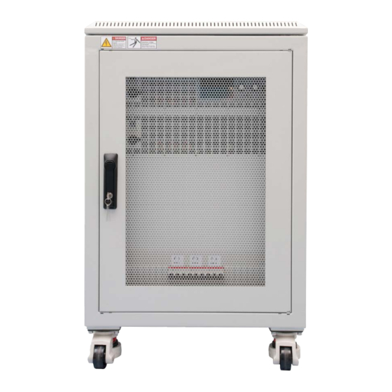
PSI 9000 15U/24U Series 1.8.4 Views Figure 1 - Front side (30 kW model in 15U) A - Power switch B - Control panel C - AC input fuses EA Elektro-Automatik GmbH Fon: +49 2162 / 3785-0 www.elektroautomatik.de Page 14 Helmholtzstr. - Page 15 PSI 9000 15U/24U Series Figure 2 - Rear side (45 kW model shown, other models look similar) D - Digital and analog interfaces E - Share Bus and remote sensing connection F - DC output G - AC input connection of the single units...
- Page 16 PSI 9000 15U/24U Series Not included by default Figure 4 - Rear side (90 kW model in 24 U) Figure 3 - Front side (90 kW model in 24U) and optional emergency off switch EA Elektro-Automatik GmbH Fon: +49 2162 / 3785-0 www.elektroautomatik.de...
- Page 17 PSI 9000 15U/24U Series EA Elektro-Automatik GmbH Fon: +49 2162 / 3785-0 www.elektroautomatik.de Page 17 Helmholtzstr. 31-37 • 41747 Viersen Fax: +49 2162 / 16230 ea1974@elektroautomatik.de Germany...
-
Page 18: Control Elements
PSI 9000 15U/24U Series 1.8.5 Control elements Figure 7- Control Panel Overview of the elements of the control panel For a detailed description see section „1.9.6. The control panel (HMI)“. Touchscreen display Used for selection of set values, menus, status and display of actual values and status. -
Page 19: Construction And Function
General description The electronic high performance power supplies of the PSI 9000 15U and PSI 9000 24U series have been de- signed for industrial high current and high power demands. Configured as mobile 19” cabinets in either 15 or 24 units of height they allow for operation in many different situations, such as electro-plating or high capacity battery test and charging. -
Page 20: Scope Of Delivery
PSI 9000 15U/24U Series 1.9.3 Scope of delivery 1 x Power supply cabinet with 2-6 installed PSI 9000 3U units 1 x 1.8 m USB cable 1 x USB stick with documentation and software (for the cabinet, further USB sticks from the power module may be included) 1.9.4... -
Page 21: The Control Panel (Hmi)
PSI 9000 15U/24U Series 1.9.6 The control panel (HMI) The HMI (Human Machine Interface) consists of a display with touchscreen, two rotary knobs, a pushbutton and an USB port. 1.9.6.1 Touchscreen display The graphic touchscreen display is divided into a number of areas. The complete display is touch sensitive and can be operated by finger or stylus to control the equipment. - Page 22 PSI 9000 15U/24U Series • Status display (upper right) This area displays various status texts and symbols: Display Description Locked The HMI is locked Unlocked The HMI is unlocked Remote: The device is under remote control from..Analog ..the built-in analog interface USB &...
- Page 23 PSI 9000 15U/24U Series 1.9.6.4 Resolution of the displayed values In the display, set values can be adjusted in fixed increments. The number of decimal places depends on the device model. The values have 4 or 5 digits. Actual and set values always have the same number of digits.
-
Page 24: Usb Port (Rear Side)
PSI 9000 15U/24U Series 1.9.7 USB port (rear side) The USB port on the rear side of the topmost unit (master) is provided for communication with the device and for firmware updates of the master. For the other units (slaves) in the cabinet, firmware updates are applied via the particular USB port of the units. -
Page 25: Share" Connector
PSI 9000 15U/24U Series 1.9.10 “Share” connector This 2 pole WAGO connector on the rear side of the units is used by the master to balance the load between all units. It must not be connected externally or used in a different way and must always remain plugged at all units to ensure safe and proper operation of the power supply cabinet. -
Page 26: Installation & Commissioning
PSI 9000 15U/24U Series Installation & commissioning Transport and storage 2.1.1 Transport • The handles on the front side of the units aren’t for carrying, but only for insertion into or re- moval from the cabinet! • Because of the weight of the units, transport by hand should be avoided where possible. If unavoidable then only the housing should be held and not on the exterior parts (handles, DC output terminal, rotary knobs). -
Page 27: Installing The Device
PSI 9000 15U/24U Series 2.3.3 Installing the device • Select the location for the device so that the connection to the load is as short as possible • Leave sufficient space behind the equipment for ventilation, at least 50 cm • For models with installed emergency off switch (optional, see 1.9.5) it’s required to leave an... -
Page 28: Connection To Ac Supply
PSI 9000 15U/24U Series 2.3.4 Connection to AC supply • Connection to an AC mains supply must only be carried out by qualified personnel! • Cable cross section must be suitable for the maximum input current of the device (see table below)! • Before plugging in the input plug ensure that the device is switched off by its mains switch! -
Page 29: Connection To Dc Loads
PSI 9000 15U/24U Series 2.3.5 Connection to DC loads Connection to transformerless DC-AC inverters (for example solar inverters) is restricted, be- cause the inverter can shift the potential of negative output (DC-) against PE (ground). Refer to section „1.8.3. Technical specifications“ for the allowed max. potential shift. - Page 30 PSI 9000 15U/24U Series 2.3.5.1 Connection points Every cabinet has bus bars on the DC output, which have 3 or 6 connection points on their lower end. Each con- nection point can be used to screw one or two cables. The table in section 2.3.5 lists the number and size of the connection points for every rated output current and power.
-
Page 31: Grounding Of The Dc Output
PSI 9000 15U/24U Series 2.3.6 Grounding of the DC output Grounding one of the DC output poles is allowed. Doing so can result in a potential shift of the grounded pole against PE. Because of insulation, there is a max. allowed potential shift of the DC output poles, which also depends on the device model. -
Page 32: Installation Of An Interface Module
PSI 9000 15U/24U Series 2.3.9 Installation of an interface module The optionally obtainable interface modules can be retrofitted by the user and are exchangeable with each other. The settings for the currently installed module vary and need to be checked and, if necessary, corrected on initial installation and after module exchange. -
Page 33: Initial Commission
PSI 9000 15U/24U Series 2.3.12 Initial commission For the first start-up after installation of the cabinet, the following procedures have to be executed: • Confirm that the connection cables to be used are of a satisfactory cross section! • Check if the factory settings of set values, safety and monitoring functions and communication are suitable for your intended application of the device and adjust them if required, as described in the manual! • Before using remote control via PC, read the additional documentation for interfaces and software! - Page 34 PSI 9000 15U/24U Series Adding a unit follows the same procedure as described in 2.3.14 and .2.3.15. Following base configurations can be extended: Power rating before Type Free slots Power rating after Current rating after 30 kW 45 kW 1,5 x nominal current before...
-
Page 35: Operation And Application
PSI 9000 15U/24U Series Operation and application Personal safety • In order to guarantee safety when using the device, it’s essential that only persons operate the device who are fully acquainted and trained in the required safety measures to be taken when working with dangerous electrical voltages • For models which can generate a voltage which is dangerous by contact, or is connected to... -
Page 36: Current Regulation / Constant Current / Current Limiting
PSI 9000 15U/24U Series 3.2.2 Current regulation / constant current / current limiting Current regulation is also known as current limiting or constant current mode (CC). The DC output current is held constant by the power supply, once the output current to the load reaches the ad- justed limit. -
Page 37: Alarm Conditions
PSI 9000 15U/24U Series Alarm conditions This section only gives an overview about device alarms. What to do in case your device indi- cates an alarm condition is described in section „3.6. Alarms and monitoring“. As a basic principle, all alarm conditions are signalled optically (text + message in the display), acoustically (if activated) and as a readable status and alarm counter via the digital interface. -
Page 38: Manual Operation
PSI 9000 15U/24U Series Manual operation 3.4.1 Switching on the device The power supply cabinets of this series are master-slave systems with one master unit and up to 5 slave units. In order for the master to find and initialise the slaves the fastest way after powering the cabinet, it should be powered last. - Page 39 PSI 9000 15U/24U Series 3.4.3.1 Menu “General Settings” Setting Description Allow remote control Selection “NO” means that the device can’t be remotely controlled over either the digital or analog interfaces. If remote control isn’t allowed, the status will be shown as “Local”...
- Page 40 PSI 9000 15U/24U Series Setting Description DC output after remote Determines the condition of the DC output after leaving remote control either man- ually or by command. • OFF = DC output will be always off when switching from remote to manual • AUTO = DC output will keep the last condition...
- Page 41 PSI 9000 15U/24U Series IF Level 1 Level 2 Level 3 Description IP Settings 1 DHCP The IF allows a DHCP server to allocate an IP address, a subnet mask and a gateway. If no DHCP server is in the network then network parameters will be set as defined in item “Manual”...
- Page 42 PSI 9000 15U/24U Series IF Ebene 1 Level 2 Level 3 Description Base ID Setup of the CAN base ID (11 Bit or 29 Bit, hex format). Default: 0h Baud Rate Setup of the CAN bus speed or baud rate in typical value be- tween 10 kbps and 1Mbps.
- Page 43 PSI 9000 15U/24U Series Element Description Com Timeout Timeout USB/RS232 (in milliseconds) Default value: 5, Range: 5...65535 Defines the max. time between two subsequent bytes or blocks of a transferred message. For more information about the timeout refer to the external programming documentation “Programming Guide ModBus &...
-
Page 44: Adjustment Limits
Changing the operating mode In general, the manual operation of a PSI 9000 15U/24U distinguishes between two resp. three operating modes, U/I and U/P and U/R, which are tied to set value input using the rotary knobs or ten-key pad. This assignment must be changed if one of the three resp. -
Page 45: Manual Adjustment Of Set Values
PSI 9000 15U/24U Series 3.4.6 Manual adjustment of set values The set values for voltage, current and power are the fundamental operating possibilities of a power supply and hence in manual operation the two rotary knobs on the front of the device are always assigned to two of the values. -
Page 46: The Meter Bars
PSI 9000 15U/24U Series Limitations of the alternative status page: • Set and actual values of power aren’t displayed and the set value of power is only indirectly accessible • The set value of resistance isn’t displayed and only indirectly accessible • No access to the settings overview (MENU button) while the DC output is on... -
Page 47: Recording To Usb Stick (Logging)
PSI 9000 15U/24U Series 3.4.10 Recording to USB stick (logging) Device data can be recorded to USB stick (preferably 2.0 / 3.0 may work, but not all vendors are supported) any- time. For specifications of the USB stick and the generated log files refer to section „1.9.6.5. USB port (front side)“. -
Page 48: Remote Control
Local period. 3.5.3 Remote control via a digital interface 3.5.3.1 Selecting an interface All models of series PSI 9000 15U/24U support the following optionally available interface modules in the standard interface slot on the master unit: Short ID Type Ports Description*... -
Page 49: Remote Control Via The Analog Interface (Ai)
PSI 9000 15U/24U Series 3.5.3.2 General information about the interface modules The master unit in the cabinet can have one of the plug-in and retrofittable modules listed in 3.5.3.1 installed. It can take over remote control of the device alternatively to the built-in USB type B on the rear side or analog interface. - Page 50 PSI 9000 15U/24U Series 3.5.4.2 Resolution The analog interface is internally sampled and processed by a digital microcontroller. This causes a limited resolu- tion of analog steps. The resolution is the same for set values (VSEL etc.) and actual values (VMON/CMON) and is 26214 when working with the 10 V range.
- Page 51 PSI 9000 15U/24U Series 3.5.4.5 Overview of the Sub-D Socket 3.5.4.6 Simplified diagram of the pins Digital Input (DI) Analog Input (AI) The DI is internally pulled up and thus it re- High resistance input (impedance V~0.5 quires to use a contact with low resistance >40 k..100 kΩ) of an operational...
- Page 52 PSI 9000 15U/24U Series • Remote control isn’t active In this mode of operation pin “REM-SB” can serve as lock, preventing the DC output from being switched on by any means. This results in following possible situations: Parameter Level of „Analog...
-
Page 53: Alarms And Monitoring
PSI 9000 15U/24U Series Alarms and monitoring 3.6.1 Definition of terms There is a clear distinction between device alarms (see „3.3. Alarm conditions“) such as overvoltage protection or overheating protection, and user defined events such as OVD (overvoltage detection). Whilst device alarms serve to protect the device by initially switching off the DC output, user defined events can switch off the DC output (Action = ALARM), but can also simply give an acoustic signal to make the user aware. - Page 54 PSI 9000 15U/24U Series Short Long Description Indication Triggers an alarm if the master unit loses contact to any slave unit. The DC Display, Master-Slave output will be switched off. The alarm can be cleared by reinitializing the MS digital Protection system.
-
Page 55: Control Panel (Hmi) Lock
PSI 9000 15U/24U Series Control panel (HMI) lock In order to avoid the accidental alteration of a value during manual operation the rotary knobs or the touchscreen can be locked so that no alteration of values will be accepted without prior unlocking. -
Page 56: Loading And Saving An User Profile
PSI 9000 15U/24U Series Loading and saving an user profile The menu “Profiles” serves to select between a default profile and up to 5 user profiles. A profile is a collection of all settings and set values. Upon delivery, or after a reset, all 6 profiles have the same settings and all set values are 0. -
Page 57: The Function Generator
PSI 9000 15U/24U Series 3.10 The function generator 3.10.1 Introduction The built-in function generator (short: FG) is able to create various signal forms and apply these to the set value of voltage or current. In manual operation, all generator functions are available for access on the front panel. In remote control, only the customisable arbitrary generator and a XY function are available. -
Page 58: Method Of Operation
PSI 9000 15U/24U Series 3.10.2.4 Possible technical complications Operation of switching mode power supplies as a voltage source can, when applying a function to the output volt- age, lead to damage of the output capacitors due to continuous charging/discharging which causes overheating. -
Page 59: Sine Wave Function
PSI 9000 15U/24U Series After setting it up, the function can be loaded. ► How to load a function After setting the values for the required signal generation, tap on the touch area The device will then load the data into the internal controller and changes the display. -
Page 60: Triangular Function
PSI 9000 15U/24U Series 3.10.6 Triangular function The following parameters can be configured for a triangular wave function: Value Range Description I(A), U(A) 0...(Nominal value - (Off)) of U, I A = Amplitude of the signal to be generated I(Off), U(Off) 0...(Nominal value - (A)) of U, I Off = Offset, based on the foot of the triangular wave 0.1 ms...36000 s... -
Page 61: Trapezoidal Function
PSI 9000 15U/24U Series 3.10.8 Trapezoidal function The following parameters can be configured for a trapezoidal curve function: Value Range Description I(A), U(A) 0...(Nominal value - (Off)) of U, I A = Amplitude of the signal to be generated I(Off), U(Off) 0...(Nominal value - (A)) of U, I... -
Page 62: 3.10.10 Arbitrary Function
PSI 9000 15U/24U Series 3.10.10 Arbitrary function The arbitrary, i. e. freely definable function offers the user a wider scope. There are 99 freely configurable sequence points available. While all have the same set of parameters, they can be configured differently so that a complex function process can be created. - Page 63 PSI 9000 15U/24U Series Schematic diagram: Applications and results: Example 2 Focusing 1 cycle of 1 sequence point: The DC values at start and end are the same but the AC (amplitude) not. The end value is higher than the start so that the amplitude increases with each new half sine wave continuously through the se- quence.
- Page 64 PSI 9000 15U/24U Series By linking together a number of differently configured sequences, complex progressions can be created. Smart configuration of the arbitrary generator can be used to match triangular, sine, rectangular or trapezoidal wave func- tions and thus, e. g. a sequence of rectangular waves with differing amplitudes or duty cycles could be produced.
- Page 65 PSI 9000 15U/24U Series 3.10.10.1 Loading and saving the arbitrary function The sequence points of the arbitrary function, which can be manually configured with the control panel of the de- vice and which are applicable either to voltage (U) or current (I), can be saved to or loaded from a common USB stick via the front side USB port.
-
Page 66: Ramp Function
PSI 9000 15U/24U Series ► How to save a sequence point table to an USB stick: Do not plug the USB stick yet or remove it. Access the function selection menu of the function generator via MENU -> Function Generator -> Arbitrary ->... - Page 67 PSI 9000 15U/24U Series In the IU function the assignment of the values is the other way round, the behaviour, however, the same. Thus the behaviour of the load or the current and power consumption can be controlled with dependance on output voltage and step changes can be created.
-
Page 68: 3.10.13 Simple Pv (Photovoltaics) Function
PSI 9000 15U/24U Series 3.10.13 Simple PV (photovoltaics) function 3.10.13.1 Preface This function uses the standard XY generator to let the power supply simulate solar panels or solar cells with certain characteristics. The device calculates an IU table from four typical values. -
Page 69: Fc Table Function (Fuel Cell)
PSI 9000 15U/24U Series Varying this parameter shifts the MPP and the PV curve along the Y axis. Also see diagram to the right. The value Irradiance is here used as a factor for the current Impp. The curve itself isn’t permanently re-calculated. - Page 70 PSI 9000 15U/24U Series 3.10.14.2 Usage The following parameters can be set for the FC table function: Value Range Description Point 1: Uoc 0 V...U Open circuit voltage at no load Point 2+3: U 0 V...U Voltage and current define the position of these two points...
-
Page 71: 3.10.15 Extended Pv Function According To En 50530
PSI 9000 15U/24U Series 3.10.15 Extended PV function according to EN 50530 3.10.15.1 Introduction This extended PV table function according to standard EN 50530 is used to simulate solar panels in order to test and rate solar inverters. It’s available since firmware versions KE 2.19 and HMI 2.11 and offers manual configuration and control, as well as remote control. - Page 72 PSI 9000 15U/24U Series 3.10.15.5 Day trend The so-called day trend is a special simulation mode for long-term tests. It processes a curve consisting of up to 100,000 user-definable points. For every processed point on that curve, the PV curve is calculated anew.
- Page 73 PSI 9000 15U/24U Series Visualisation: Without interpolation - the curve results in steps With interpolation - the curve remains linear An example: the dwell time of the 3450 curve point is defined as 3 minutes, which is 180 seconds. There will be 180 / 0.5 -1 = 359 intermediate steps calculated and set until reaching the 3451...
- Page 74 PSI 9000 15U/24U Series 3.10.15.8 Configuration step by step Starting point In MENU->Function Generator->2nd page->XY-Table you will find the PV functions. Select PV DIN EN 50530. Step 1: Technology selection The extended PV function requires to select the panel technology of the solar panel which is going to be simulated.
- Page 75 PSI 9000 15U/24U Series Step 4: Global limits This configuration screen allows to limit voltage and power globally for the simulation. The current, in this table based simulation, is taken from the calculated PV table which also is an IU table.
-
Page 76: 3.10.16 Remote Control Of The Function Generator
PSI 9000 15U/24U Series 3.10.16 Remote control of the function generator The function generator can be remotely controlled but configuration and control of the functions with individual commands is different from manual operation. The external documentation “Programming Guide ModBus & SCPI”... -
Page 77: Other Applications
This way of operation refers to the use of a source, in this case a power supply of series PSI 9000 15U/24U, and a sink, in this case one or several electronic loads of series ELR 9000 or EL 9000 B. The source and the sink function al- ternatingly in order to test a device, such as a battery, by deliberately charging and discharging it as part of a functional or final test. - Page 78 PSI 9000 15U/24U Series 3.11.4.2 Connecting devices to a 2QO There are several ways to connect source(s) and sink(s) to make a 2QO, but for this power supply series this configuration is recommend: 1 e-load and 1 power supply, plus 1 test object (E.U.T).
-
Page 79: Other Information
PSI 9000 15U/24U Series Other information Special characteristics of master-slave operation The units in the cabinet run in master-slave operation. This can cause additional problem situations which do not occur when operating units outside of master-slave. For such occurrences the following regulations have been defined: • If the DC part of one or more slave units is switched off due to a defect or overheating etc., the entire cabinet... -
Page 80: Service And Maintenance
PSI 9000 15U/24U Series Service and maintenance Maintenance / cleaning The device needs no maintenance. Cleaning may be needed for the internal fans, the frequency of cleanse is depending on the ambient conditions. The fans serve to cool the components which are heated by the inherent power loss. -
Page 81: Calibration
PSI 9000 15U/24U Series Calibration 5.3.1 Preface All PSI 9000 series feature a function to re-adjust the most important output values when doing a calibration with possible requirement of re-adjustment in case these values have moved out of tolerance. The re-adjustment is limited to compensate small differences of up to 2% of the max. - Page 82 PSI 9000 15U/24U Series 5.3.3.1 Calibrating the set values ► How to calibrate the output voltage Connect a multimeter to the DC output. Connect a load and set its current to approx. 5% of the nominal current of the power supply, in this example ≈50 A, and 0 V (if the load is electronic).
-
Page 83: Contact And Support
PSI 9000 15U/24U Series 5.3.3.4 Save and exit After calibration you may furthermore enter the current date as “calibration date” by tapping in the selection screen and enter the date in format YYYY / MM / DD. Last but not least save the calibration data permanently by tapping Leaving the calibration selection menu without tapping “Save and exit”... - Page 84 EA Elektro-Automatik GmbH & Co. KG Development - Production - Sales Helmholtzstraße 31-37 41747 Viersen Germany Fon: +49 2162 / 37 85-0 Fax: +49 2162 / 16 230 Mail: ea1974@elektroautomatik.de Web: www.elektroautomatik.de...
Need help?
Do you have a question about the PSI 9000 15U and is the answer not in the manual?
Questions and answers