Table of Contents
Advertisement
Advertisement
Table of Contents

Related Manuals for Titan VS-32-L


Summary of Contents for Titan VS-32-L
- Page 1 Operating and Maintenance Instructions VS-32-L 0003 Pneumatic Strapping head for steel strap Seal Important! Do not throw these instructions away. The customer agrees to make these operating instructions understandable to all operating and service personnel. B 13 GB 11/13...
-
Page 2: Table Of Contents
Finding the time required for a strapping operation ............13 5.3. Smallest support with different packing items ..............14 5.4. Measurements and assembly dimensions VS-32-L ............15 5.5. Pneumatic plan equipment (head control system) ............16 5.6. Functional time diagram ....................17 5.7. -
Page 3: Manufacturer Details
Manufacturer details TITAN Umreifungstechnik GmbH & Co. KG Berliner Straße 51 – 55 58332 Schwelm Deutschland Tel.: +49 (2336) 808-0 Fax: +49 (2336) 808-208 E-Mail: info@titan-schwelm.de Web: www.titan-schwelm.de VS-32-L B 13 GB 07/10... -
Page 4: General
The contents of this document must not be duplicated, handed to third parties, published or saved in any form, neither fully nor partly, without prior written permission by TITAN Umreifungstechnik GmbH & Co.KG. is a registered trademark of TITAN Umreifungstechnik GmbH & Co.KG. - Page 5 All functions are released by solenoid valves. Valves are equipped with actuating magnets 24 V DC (direct current voltage). The mains voltage of the VS-32-L head is 400 V 50/60 Hz. The connected load of the welding unit is 6,6 kVA. Protect by fuse 16 A (slow-blow).
- Page 6 The argon/welding gas consumption amounts to 2 l per seal. When a 50 l gas bottle with a filling pressure of 200 bar is used, approx. 5000 seals are possible, in case of 300 bar approx. 7500 seals. The welding electrode can be ground approx. 100 times. VS-32-L B 13 GB 07/10...
-
Page 7: Safety Regulation
They must neither be loose nor have been removed. Do not let your hands get into the channel area and below the packing items during the strapping operation. Attention! Risk of squeezing! VS-32-L B 13 GB 07/10... - Page 8 Attention! The lower part of the strap jumps upward. Consider the strong development of noise during longer operations. Therefore, protect your health. Exclusively use original TITAN spare parts! The use of spare parts not made by TITAN excludes guarantee adjustments and liability.
-
Page 9: Life Phases Of The Unit
Automatic mode: Automatic processing of all movements. In automatic mode attention must be paid that no points with the risk of squeezing may occur between the feed installations (e.g. roller conveyors) and the movable strapping unit. VS-32-L B 13 GB 07/10... - Page 10 In the same way, motors and electric modules like control system, switches and cables must be admitted to separate waste disposal. Take such elements to the appropriate waste management. VS-32-L B 13 GB 07/10...
-
Page 11: Technical Data
700 mm Strap tensions: 4000-20000 N adjustable Air pressure: 5-6 bar flow pressure Air consumption: approx. 0,2-0,3 m³ per strapping operation Weight: 200 kg Dimensions: l 680 x w 580 x h 750 mm VS-32-L B 13 GB 33/06... -
Page 12: Technical Data Of The Welding Unit
< 68 dB (A) in case of maximum admissible working point at standard load according to VDE 0544-1 or EN 60974-1. Sound data are measured according to DIN 45635. Measurements are performed at a distance of 1 m away from the welding current source. VS-32-L B 13 GB 33/06... -
Page 13: Finding The Time Required For A Strapping Operation
= 0,5 s Ignition = 0,2 s Sealing selected = 1,5 s Cooling selected = 1,7 s Seal, released fixed time = 1,3 s Head backward, retraction selected = 1,0 s Σ Total time 16,8 s VS-32-L B 13 GB 04/13... -
Page 14: Smallest Support With Different Packing Items
VS 32-R For small packing units, design R Expansive packing item: 180 mm 150 mm Slit coil: 180 mm 150 mm Hexagon pipe bundle: 160 mm Round packing item: Ø 800 mm | Ø 700 mm VS-32-L B 13 GB 26/06... -
Page 15: Measurements And Assembly Dimensions Vs-32-L
5.4. Measurements and assembly dimensions VS-32-L Intake of strap VS-32-L B 13 GB 33/06... -
Page 16: Pneumatic Plan Equipment (Head Control System)
5.5. Pneumatic plan equipment (head control system) VS-32-L B 13 GB 11/13... -
Page 17: Functional Time Diagram
5.6. Functional time diagram VS-32-L B 13 GB 36/09... -
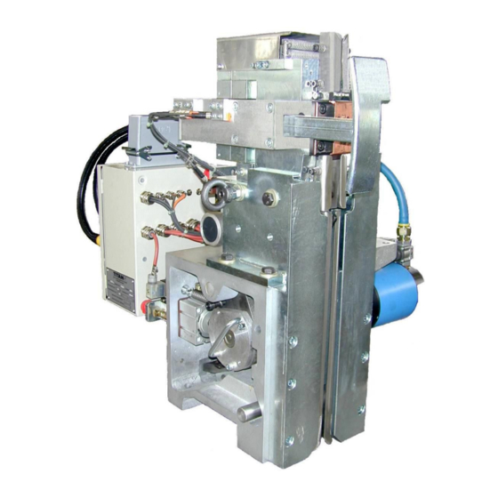
Page 18: Arrangement And Designations
Device to feed the torches with welding gas and welding current; it also comprises the electrical units for the direct gas flow and current flow control (e.g. solenoid valve etc.), further the electrical link between the strapping head and the machine control system. Fig. 1: Main assembly units VS-32-L B 13 GB 36/09... -
Page 19: Designations
Accumulator full on the machine Accumulator empty on the machine End of strap on the machine Motors: Transport motor Tensioning motor Sealing motor Cylinder: Lift cylinder transport slide Pressing cylinder tensioning rocker VS-32-L B 13 GB 33/06... - Page 20 Cooling time Further flow of gas Sealing time Welding flow Start precise movement if B14 not available Cleaning burner cell Monitoring time strap overlapping Monitoring operating time: Feed / Return / Tensioning / Welding / Seal VS-32-L B 13 GB 11/13...
-
Page 21: Switches
Signals head on packing item. Starts the fast transport back or strap tensioning. Lifts the transport rocker during insertion of strap. B10: Actuates the welding station (sealing motor). Cam gear positions can be approached individually. VS-32-L B 13 GB 33/06... -
Page 22: Positions Of The Switches, Valves, Pressure Controllers And Motors
6.3. Positions of the switches, valves, pressure controllers and motors B3/B4 VS-32-L B 13 GB 33/06... -
Page 23: Functional Description
7.1. Process description 7.1.1. Insertion of strap Before the insertion of the strap into the TITAN strapping head type VS-12-L attention must be paid that the beginning of the strap has been cut cleanly and sprightly. The beginning of the strap is then inserted... -
Page 24: Strap Feed, Precise Movement
The adjustable strap tension can be between 4000 and 20000 N. It can at the multi-functional module (569) see chapter 8.4 being adjusted. The tension pressures achieved can be read on the pressure gauge installed. VS-32-L B 13 GB 33/06... -
Page 25: Closing Strap Gripper 2
The sealing motor M3 is switched on and operates until the 0 position of the head has been reached. The tensile springs (116) close the welding station. Switch ring 1 (55) then occupies switch B3. - A new strapping cycle may begin. - VS-32-L B 13 GB 33/06... -
Page 26: Positions On The Cam Gear
Pos. F Gripper 2 closed, Welding station swung open, keeping tension of strap, pressing, retracting strap from cutting area cutting and sealing the straps B3 = OFF B3 = OFF B4 = ON B4 = ON VS-32-L B 13 GB 26/06... -
Page 27: Description Of The Welding Operation
15 °. Angles being too obtuse provide good ignitability, but it is their disadvantage that they are consumed too quickly which in turn increases ignition distance. Sharpening the ignition needle should be done by means of a TITAN-Sharp grinder. -
Page 28: Adjustments
Switch B1 should be set such that the gap between pusher (71) and switch (85) is max.1 mm. Counter switch: Switch B2 (446) is screwed into transport rocker (529) such that the gap between shaft (385) and switch is 1 mm and fixed by a locknut. VS-32-L B 13 GB 26/06... - Page 29 2 (987) in the axial direction of the slide is possible. The switching length between B7 "Head before packing item" and B8 "Head on packing item" can be set to max. 115 mm. VS-32-L B 13 GB 26/06...
-
Page 30: Setting The Zero Position
(32) fits closely to the radius of the opening curve (14). The curve flank is then vertical to the partial axis. Positions 1 to 3 are engraved on the toothed wheel (29) and can be controlled there. Curve flank VS-32-L B 13 GB 26/06... -
Page 31: Setting The Air Pressure
Max. strap tension, the fastest strap feed speed Selection via speed valve Y2 in the multi-functional block and related consumer valve Y3, Y4 to Y6. This setting makes for the speed of the sealing process (Welding station). VS-32-L B 13 GB 11/13... - Page 32 Note! Check the flow pressure at the tapping point. Flow pressure exceeding 6 bar results in increased wear at the compressed air motors. Pressure being too low results in reduced output. VS-32-L B 13 GB 33/06...
-
Page 33: Setting The Quantity Of Gas
Caution! Gas bottles are to be protected against dangerous heating up (over 50°C) by heating elements or open flames. Bottles at a well- ventilated place store and against falling down secure. VS-32-L B 13 GB 26/06... -
Page 34: Setting The Distance Between Electrodes
The electrode should project approx. 30 mm. Manually screw in casing. Use the torch wrench preset to slip the electrode into the casing to size and screw it. Manually screw the gas nozzle firmly. VS-32-L B 13 GB 26/06... -
Page 35: Setting The Torch
If the clamping sleeve housing, the clamping sleeve or the welding electrode will be exchanged separately, the adjusting of the burner has to be controlled. Due to the modified constellation it is possible that the distance between welding electrode and support of the burner change. VS-32-L B 13 GB 05/10... -
Page 36: Setting The Welding Parameters
[s] 19 x 0,8 19 x 1,0 25,4 x 0,8 25,4 x 1,0 31,75 x 0,8 31,75 x 0,9 31,75 x 1,0 Painted strap! Galvanised or zinc dust painted strap cannot (!) be welded. VS-32-L B 13 GB 26/06... -
Page 37: Maintenance
9.1. General Regular and careful maintenance provides for the permanent readiness for operation of the strapping head of the type VS-32-L. The strapping head must always be kept clean. Always keep strap guidance's and sealing sector free of pollution and foreign substances. -
Page 38: Maintenance Intervals
Cutting edge (upper strap) Clamp 1 Bad welding. Cutting Good welding. mark by cutter Bad welding. Sliding at clamp 2, cutting edge of upper strap is not positioned at the cutting mark, therefore loose strapping. VS-32-L B 13 GB 33/06... -
Page 39: Lubricating Points
However, in case of ambient temperatures of below +5 °C there is the risk of icing. In that case dried air or icing-inhibiting lubricants (e.g. "Killfrost Anti Eis") are recommended. Caution! Wear breathing mask when using antifreeze agents. VS-32-L B 13 GB 26/06... -
Page 40: Maintenance Of The Transport Unit
The counter roller (420) found below and the guidance’s (4251/4261) can then be cleaned (fig. 11). Mounting is performed in the reverse order. Slightly lubricate all parts (exc. screws). VS-32-L B 13 GB 26/06... - Page 41 Fig. 7: Remove retention Fig. 6: Loosen flap protective ledge. pin. backside. 3401 3481 Fig. 8: Swing out counter Fig. 9: Remove rocker Fig. 10: Dismount bearing elements. cover. tensioning wheel. Fig. 11: Dismount transport wheel. VS-32-L B 13 GB 26/06...
-
Page 42: Maintenance Of The Clamp Guide
(4) and base plate (1) (figures 13 to 14). Then the clamp guide can be removed from the sealing unit (fig. 15). If required, the cutting plate acc. to section 9.7 can be dismounted. Mounting is performed in the reverse order. VS-32-L B 13 GB 04/13... - Page 43 Fig. 12: Relieving pressure springs. Fig. 13: Loosening cylinder screw. 1721 Fig. 15: Remove clamping guidance. Fig. 14: Remove seal. Fig. 16: Cleaning base plate. VS-32-L B 13 GB 33/06...
-
Page 44: Maintenance Of The Cutter
The sealing unit can now be tilted open and the cutter guidance can be removed from the clamp guide by the loosening of the cheese-head screw (fig. 18). Mounting is performed in the reverse order. Fig. 18: Dismounting cutter guide. Fig. 17: Sealing unit tilted open. VS-32-L B 13 GB 04/13... -
Page 45: Dismounting The Torch, Replacement Of Electrode
Manually unscrew the gas nozzle (668). Detach the tensioning sleeve casing (666) by means of torch wrench (270). Remove igniting electrode (669) and sharpen it by means of TITAN-SHARP. Insertion of the igniting electrode (669) into the tensioning sleeve casing. The electrode should project approx. -
Page 46: Dismounting And Mounting The Clamp
After the check or the replacement slip the clamp including holder onto the rocker (37) and link it to the bolt. Fasten cover and close sealing unit. Slightly lubricate all sliding surfaces. Finally suspend the tension springs. Fig. 21: Swinging out sealing unit. Fig. 22: Remove linking bolts. VS-32-L B 13 GB 26/06... -
Page 47: Dismounting And Mounting The Torch Holder
Mounting is performed in reverse order. Slightly lubricate torch holder on the sliding surfaces. Fig. 23: Swing out sealing unit. Fig. 24: Remove bar. Fig. 26: Swing out torch holder. Fig. 25: Dismount pressure springs. VS-32-L B 13 GB 26/06... -
Page 48: Fault Detection - Remedy
Extend overlapping timer t1. the straps are clamped, the tension motor switches off. Strap tension is relieved. Increase pressure at pressure controller DR3. Strap tension reduced too much. See section 8.4 VS-32-L B 13 GB 33/06... - Page 49 Welding time and welding current too Increase Welding time and through. short / low. welding current. Welding spot with hole. Welding current too high. Paint coat Reduce welding current t6. on strapping material to thick. Replace strapping material. VS-32-L B 13 GB 33/06...
-
Page 50: Declaration Of Incorporation
11. Declaration of incorporation VS-32-L B 13 GB 07/10... - Page 51 Kunststoffband Verschlusshülsen Seals Chapes Zubehör Accessories Accessoires TITAN Umreifungstechnik GmbH & Co. KG Postfach 440, 58317 Schwelm Berliner Straße 51-55, 58332 Schwelm Telefon: +49 (0) 23 36 / 8 08-0 Telefax: +49 (0) 23 36 / 8 08-208 E-Mail: info@titan-schwelm.de www.titan-schwelm.de...
Need help?
Do you have a question about the VS-32-L and is the answer not in the manual?
Questions and answers