Table of Contents
Advertisement
Available languages
Available languages
Quick Links
Wichtig!
Bitte diese Anleitung nicht wegwerfen. Der Kunde
verpflichtet sich, diese Betriebsanleitung allen
Bedienungs- und Servicepersonen verständlich zu
machen.
Important!
Do not dispose of this manual. It is the customer's
responsibility to ensure that all operators and
servicemen read and understand this manual.
Important!
Ne jetez pas ce manuel. Il est de la responsabilité du
client de s´ assurer que tous les opérateurs et
techniciens d´entretien lisent et comprennent le
contenu de ce manuel.
Betriebsanleitung
-Originalbetriebsanleitung-
Instruction manual
-Translation of the original instructions-
Notice d´instructions
-Traduction de la notice originale-
H 265 EU 34/21
MAX
001100
265
Pneumatisches
Umreifungsgerät für
Stahlband
Pneumatic strapping
tool for steel strap
Appareil de cerclage
pneumatique pour
feuillard d´acier
Advertisement
Chapters
Table of Contents

Related Manuals for Titan MAX


Summary of Contents for Titan MAX
- Page 1 Betriebsanleitung -Originalbetriebsanleitung- Instruction manual -Translation of the original instructions- Notice d´instructions -Traduction de la notice originale- 001100 Pneumatisches Umreifungsgerät für Stahlband Pneumatic strapping tool for steel strap Appareil de cerclage pneumatique pour feuillard d´acier Wichtig! Bitte diese Anleitung nicht wegwerfen. Der Kunde verpflichtet sich, diese Betriebsanleitung allen Bedienungs- und Servicepersonen verständlich zu machen.
-
Page 2: Table Of Contents
Inhaltsverzeichnis Seite Angaben zum Hersteller / Manufacturer details / Indication au fabricant ....3 Allgemeines ........................ 4 2.1 Bestimmungsgemäße Verwendung ..............5 2.2 Hinweis zum Umweltschutz ................. 5 Technische Daten ....................... 6 Sicherheitsvorschriften ..................... 7 Inbetriebnahme ......................11 5.1 Aufhängen des Gerätes ..................11 5.2 Druckluftaufbereitung und Anschluss ..............12 Bedienung........................13 6.1 Aufbau ........................13... -
Page 3: Angaben Zum Hersteller / Manufacturer Details / Indication Au Fabricant
Angaben zum Hersteller / Manufacturer details / Indication au fabricant TITAN Umreifungstechnik GmbH & Co. KG Berliner Straße 51-55 D-58332 Schwelm Tel.: +49 (2336) 808-0 Fax: +49 (2336) 808-208 E-Mail: info@titan-schwelm.de Web: www.titan-schwelm.de 3 / 63 H 263 EU 27/11... -
Page 4: Allgemeines
Mühelose Verarbeitung von 32 x 0,8 mm MB Copyright © TITAN Umreifungstechnik GmbH & Co.KG 2011 Alle Rechte vorbehalten. Der Inhalt dieses Dokumentes darf ohne vorhergehende schriftliche Genehmigung durch die TITAN Umreifungstechnik GmbH & Co.KG in keiner Form, weder ganz noch teilweise vervielfältigt, weitergegeben, verbreitet oder gespeichert werden. -
Page 5: Bestimmungsgemäße Verwendung
2.1 Bestimmungsgemäße Verwendung Dieses Gerät ist zum Umreifen von schweren Packgütern wie Profilstähle, bzw. Bunde, Rohre, Coils etc. bestimmt. Das Gerät wurde für eine sichere Bedienung während des Umreifens entwickelt und gebaut. Das Gerät ist für das Umreifen mit Verpackungsstahlbändern bestimmt. Das Umreifungsgerät erfüllt die deutschen und europäischen Sicherheitsanforderungen und stimmt überein mit den Bestimmungen folgender EG-Richtlinien:... -
Page 6: Technische Daten
L = 410 mm B = 195 mm H = 220 mm mit Aufhängung: L = 450 mm H = 300 mm Spannkraft: einstellbar max. 8000 N Spanngeschwindigkeit: 110 mm/sek. Luftdruck: max. 6,0 bar min. (hochfeste Qualität) 5,0 bar Luftverbrauch: 11 Nl/sek. -
Page 7: Sicherheitsvorschriften
Das Umreifen mit Kunststoffband ist mit diesem Gerät nicht möglich. Gewährleistung und Haftung Die TITAN Umreifungstechnik GmbH & Co. KG gewährt auf alle von Ihr verkauften Umreifungsgeräte eine Garantie für die Dauer von 6 Monaten. Die Garantie umfasst alle Mängel die nachweisbar auf mangelnde Fertigung oder Materialfehler zurückzuführen sind. - Page 8 Die Nichtbeachtung nachstehender Sicherheitsbestimmungen, sowie Fehler in der Handhabung des Gerätes können schwerwiegende Verletzungen zur Folge haben. Vorsicht! Arbeitsbereich Verschließer Pos. 1 + Spannrad Pos. 2 Nicht in den Arbeitsbereich des Geräts fassen. Vorsicht! Arbeitsbereich Verschließer Pos. 1 + Spannrad Pos. 2 Kleidung nicht in den Arbeitsbereich gelangen lassen.
- Page 9 Sicherheitsbestimmungen entspricht! Original Verwenden Sie nur Original TITAN Verschlusshülsen! TITAN Luftdruck nicht überschreiten! max. 6,0 bar Den vorgeschriebenen max. Luftdruck von 6,0 bar nicht überschreiten. Original Anschlusskupplung verwenden. Es dürfen nur Anschlusskupplungen verwendet werden, die den Sicherheitsvorschriften entsprechen. 9 / 63...
- Page 10 Gas- oder Druckluftflasche angeschlossen werden. Dieses Gerät darf nur von Personal bedient werden, das in der Handhabung unterwiesen wurde. Sprechen Sie den TITAN-Verpackungsberater an, wenn Sie hierzu Fragen haben. Der Einsatz eines nicht empfohlenen Bandes kann zu Bandreißern während des Spannvorganges und zu schlechten Verschlussqualitäten führen.
-
Page 11: Inbetriebnahme
Inbetriebnahme 5.1 Aufhängen des Gerätes Das Gerät besitzt einen schwenkbaren Aufhängebügel, an dem es in den drei wichtigen Arbeitslagen, an einem Federzug (Balancer) aufgehängt werden kann. Normallage Vertikallage Horizontallage Verwenden Sie nur einen Federzug (Balancer), der den Sicherheitsbestimmungen entspricht und für die technischen Spezifikationen (s. -
Page 12: Druckluftaufbereitung Und Anschluss
Zerstörung des Druckluftmotors zur Folge hat! Garantieleistungen sind in diesem Fall ausgeschlossen. max. Betriebsdruck 6 bar. Achtung! Gefahr von Bandreißern! Das Band kann reißen wenn der Betriebsdruck von 6 bar überschritten wird. Bandreißer können zu Verletzungen des Bedieners führen. -
Page 13: Bedienung
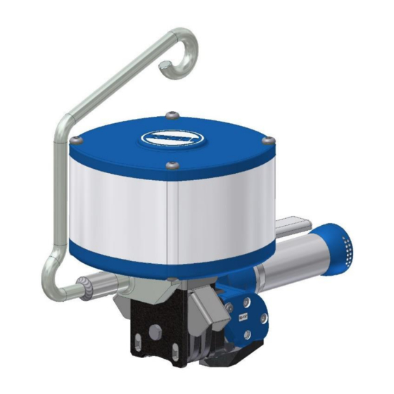
Bedienung 6.1 Aufbau 41/132 Luftanschlussnippel Spannhebel Spannkörper Verschlusshebel Gleitplatte 41/132 Transportrad Lüfthebel Druckluftmotor Aufhängung Zylinder 6.2 Funktionsprinzip 1. Band von Hand durch die Hülse führen, 2. Bandanfang umbiegen 3. Spannen mit Spannrad 4. Verschließen durch Einkerben der Hülse 5. Trennen des zugeführten Bandes 13 / 63 H 265 EU 27/11... -
Page 14: Bedienung Des Gerätes
6.3 Bedienung des Gerätes Vorsicht! Schützen Sie sich! Beim Arbeiten Augen-, Gesicht und Handschutz (schnittfeste Handschuhe) tragen. Umführen des Stahlbandes Das Stahlband wird vom Abroller durch die Verschlusshülse um das Packgut und erneut durch die Hülse geführt. Umbiegen des Bandanfanges Der Bandanfang ca. - Page 15 Durch Drücken der roten Stoptaste kann der Spannvorgang unterbrochen werden. Max mit Nadellager (keine automatische Aufrechterhaltung der Spannkraft): Durch Verwendung des MAX mit Nadellager besteht nach Erreichen der Spannkraft (wie oben beschrieben) die Möglichkeit, die Umreifung zu lösen und neu am Packstück zu positionieren.
-
Page 16: Einstellungen
Einstellungen 7.1 Abstand zwischen Transportrad und Gleitplatte Der Abstand zwischen Transportrad 41/132 und Gleitplatte 129 soll max. 0,2 mm betragen. Transportrad und Gleitplatte dürfen sich nicht berühren. 41/132 Einstellen: Lösen der Mutter 164 mittels Maulschlüssel 10 mm. Mit Maulschlüssel 12 mm über die Stellschraube 163 das Spaltmaß... -
Page 17: Wartung
Wartung 8.1 Reinigung des Gerätes Schmutz und Abrieb beeinträchtigen die Funktion des Gerätes. Deshalb folgende Bereiche wöchentlich säubern. Nach Möglichkeit mit Druckluft ausblasen (Schutzbrille tragen). Einlegeschlitz Hohlräume der Verschlusszange Transportrad Gleitschraube Danach mit feinem handelsüblichem Sprühöl einölen. Verwenden Sie bitte aus gesundheitlichen Gründen keine lösungsmittelhaltigen Reinigungsmittel. -
Page 18: Konformitätserklärung
Konformitätserklärung 18 / 63 H 265 DE 14/12... -
Page 19: English
10. English Table of contents Page Angaben zum Hersteller / Manufacturer details / Indication au fabricant ....3 General ........................20 2.1. Intended use ....................21 2.2. Environmental protection notice ..............21 Technical data ......................22 Safety Regulations ....................23 Initial operation......................27 5.1. Suspension of the unit ..................27 5.2. -
Page 20: General
The contents of this document must not be duplicated, handed to third parties, published or saved in any form, neither fully nor partly, without prior written permission by TITAN Umreifungstechnik GmbH & Co.KG. is a registered trademark of TITAN Umreifungstechnik GmbH & Co.KG. -
Page 21: Intended Use
2.1. Intended use This tool is made for strapping of heavy packages such as sectional steel, tubes, coils, etc. The tool is designed and manufactured for safe handling during the strapping operation. This tool is intended for strapping with steel strap material. The strapping tool complies with the German and European safety standards and is in accordance with. -
Page 22: Technical Data
= 410 mm B = 195 mm H = 220 mm Incl. suspension: = 450 mm H = 300 mm Tension force: adjustable max. 8000 N Tensioning speed: 110 mm/sec. Air pressure: max. 6.0 bar min. (high-strength quality) 5.0 bar Air consumtion: 11l/sec. -
Page 23: Safety Regulations
The use of plastic straps is not allowed with this device. Warranty and liability TITAN GmbH & Co. KG grants a guarantee of six (6) months for all strapping units sold by it. Such guarantee covers all defects of which evidence can be given that they result from faulty manufacture or material defects. - Page 24 Failure to comply with the following safety instructions, in addition to errors in handling the device, can result in serious injuries. Caution! Work area - Locking unit - Item 1 + Tensioning wheel - Item Do not reach into the work area of the equipment. Caution! Work area - Locking unit - Item 1 + Tensioning wheel - Item Make sure that clothes cannot get into the work area.
- Page 25 Only use original TITAN locking sleeves! TITAN Do not exceed air pressure! max. 6,0 bar Do not exceed the max. air pressure of 6.0 bar required. Use original reception couplings. Only reception couplings meeting safety requirements may be used. 25 / 63...
- Page 26 This unit may only be operated by staff having been instructed as to the handling of the unit. In case of questions do not hesitate to contact the TITAN packing consultant. Working place Keep your working place tidy. Disorder at the working place may lead to the risk of accidents.
-
Page 27: Initial Operation
Initial operation 5.1. Suspension of the unit The unit is provided with a swinging suspension shackle on which it can be suspended in the three important working positions (anti-g) by means of a balancer). Normal position Vertical position Horizontal position Only use a balancer that meets the safety regulations and is suitable for the technical specifications (see chapter Technical Data) of this equipment. -
Page 28: Compressed Air Preparation And Port
In no case it is allowed to run the tool without oil being in the lubricator of the maintenance unit, as this would immediately destroy the compressed air motor. No warranty in that case. Max. operating pressure 6 bar. Attention! Risk of tearing band! The band can get torn when the operating pressure of 6 bar is exceeded. -
Page 29: Operating Instructions
Operating Instructions 6.1. Structure 41/132 Compressed air port nipple Tension lever Tension element Locking lever Guide plate 41/132 Transport wheel Lifting lever Compressed air motor Suspension Cylinder 6.2. Functional principle 1. Manually lead band through the sleeve, 2. Bend beginning of band, 3. -
Page 30: Operating The Unit
6.3. Operating the unit Protect yourself! Always wear eye, face and hand protection (cut-resistant gloves) when working. Strapping the steel band The steel band is routed from the uncoiler through the locking sleeve around the packing item and again through the sleeve. - Page 31 Max with needle bearing (no automatic maintaining of the tension force): The MAX with needle bearing allows for loosening and repositioning of the strapping at the package after reaching the tension force (as described afore). Therefore, press the stop button, reposition the strap and repeat the tensioning process.
-
Page 32: Operating Instructions
Operating Instructions 7.1. Distance between transport wheel and guide plate The distance between transport wheel 41/132 and guide plate 129 is max. 0.2 mm. The transport wheel and the guide plate may not come into contact with each other. 41/132... -
Page 33: Maintenance
Maintenance 8.1. Cleaning and maintenance of the unit Dirt and abrasion impair the function of the unit. Therefore clean the following areas every week. If possible, perform air-cleaning (wear protective glasses). Insertion slot. Hollow spaces of the sealing pincers. Transport wheel. Guide screw Then oil it with a commercial spray oil. -
Page 34: Declaration Of Conformity Of The Machinery
Declaration of conformity of the machinery 34 / 63 H 265 EU 14/12... -
Page 35: Français
11. Français Sommaire Page Angaben zum Hersteller / Manufacturer details / Indication au fabricant ....3 Géneralités .........................36 2.1. Utilisation conventionnelle ................37 Remarque relative à la protection de l’environnement ........37 2.2. Données techniques ....................38 Prescriptions de sécurité ..................39 Mise en service ......................43 Suspension de l’appareil .................43 5.1. - Page 36 Copyright © TITAN Umreifungstechnik GmbH & Co.KG 2011 - Tous droits réservés. Toute photocopie, reproduction, diffusion, distribution intégrale ou partielle de ce manuel nécessite l'accord préalable, explicite et écrit de la société TITAN Umreifungstechnik GmbH & Co.KG. Il ne doit être ni reproduit, ni transmis, ni diffusé sous n'importe quelle forme.
- Page 37 2.1. Utilisation conventionnelle Cet appareil est destiné au cerclage de colis lourds comme les profilés d’acier, et paquets, tubes, bobines etc. L’appareil a été conçu et construit pour assurer un cerclage en toute sécurité. L’appareil est destiné au cerclage avec des feuillards d’emballage en acier L’appareil de cerclage satisfait aux exigences allemandes et européennes en matière de sécurité...
- Page 38 H = 300 mm Effort de serrage: réglable,. 8000 N Vitesse de serrage: 110 mm/sec. Pression d’air: max. 6.0 bar min. (Qualité hutment résistante) 5 bar Consommation d’air: 11 Nl/sec. pour serrage Ni pour fermeture G ¼“ Raccord pour air comprimé:...
- Page 39 Le cerclage avec la bande en matière plastique n'est pas possible avec cet appareil. Garantie et responsabilité La société TITAN GmbH & Co. KG accorde une garantie de 6 mois sur tous les appareils de cerclage qu’elle commercialise. Cette garantie englobe tous les défauts dont on peut prouver qu’ils sont dus à...
- Page 40 Le non-respect des consignes de sécurité figurant ci-dessous, ainsi que les erreurs de manipulation de l’appareil peuvent entraîner des blessures graves. Prudence ! Zone de travail scelleur pos. 1 + roue de serrage pos. 2 Ne mettez pas les mains dans la zone de travail de l'appareil. Prudence ! Zone de travail scelleur pos.
- Page 41 Pendant le cerclage, il ne doit pas se trouver de main ni d’autre partie du corps entre le feuillard et la marchandise. Utilisez uniquement des pièces de rechange TITAN d’origine! L’emploi d’autres pièces de rechange exclut toute prestation de garantie et toute responsabilité...
- Page 42 Cet appareil doit impérativement être utilisé par du personnel qui a été familiarisé avec son utilisation. Contactez votre Conseiller emballage TITAN si vous avez des questions à ce sujet. Poste de travail Maintenez en ordre votre zone de travail. Le désordre présente des risques d’accident.
- Page 43 Mise en service 5.1. Suspension de l’appareil L’appareil possède une anse de suspension bascula blé permettant de le suspendre par dispositif à ressort («balancer») dans les trois principales positions de travail, en lévitation. Position normale Position verticale Position horizontale Utilisez seulement un équilibreur ("balancer"), qui est conforme aux dispositions de sécurité...
- Page 44 5.2. Compression et alimentation d’air comprimé Le moteur et le cylindre à air comprimé sont lubrifiés par les embruns ’huile de air comprimé. Une compression d’air parfaite est donc une condition impérative pour un bon fonctionnement de l’appareil. Cette condition ne peut être remplie que par un conditionneur 3/8“...
- Page 45 Manuel d’instruction 6.1. Construction 41/132 Raccord fileté d’alimentation en Levier de serrage air comprimé Levier de fermeture Corps de serrage Vis coulissante 41/132 Roue de transport Moteur à air comprimé Levier d’aération Cylindre Suspension 6.2. Principe de fonctionnement 1. Guider le feuillard à travers la douille manuellement, 2.
- Page 46 6.3. Utilisation de l’appareil Protégez-vous! Pendant le travail, portez des dispositifs de protection pour les yeux, le visage et les mains (gants anti-cisaillement). Encerclement du feuillard d’acier Le feuillard d’acier est passé par la douille de fermeture depuis le dévidoir, guidé autour de la marchandise et de nouveau passé...
- Page 47 Max à roulement à aiguilles (pas de maintien automatique de la force de serrage): En utilisant le MAX à roulement à aiguilles, il est possible de desserrer le cerclage et de le repositionner sur le colis après l’atteinte de la force de serrage (comme décrit ci-dessus).
- Page 48 Reglages 7.1. Ecartement entre la molette et la pastille lisse L’écartement entre la molette 41/132 et la pastille lisse 129 ne peut pas dépasser 0.2 mm. La molette et la pastille lisse ne peuvent pas se toucher. 41/132 Réglage: Desserrer l’écrou 164 au moyen d’une clé plate de 10.
- Page 49 Ajustement 8.1. Maintenance La crasse et l’usure entravent le fonctionnement de l’appareil. C’est pourquoi les parties suivantes doivent être nettoyées chaque semaine. Dans la mesure du possible, purger à l’air comprimé (porter des lunettes de protection). Fente d’insertion Espaces creux de la pince de fermeture Roue de transport Vis coulissante Ensuite, graisser à...
- Page 50 Déclaration CE de conformité des machines 50 / 63 H 265 EU 14/12...
-
Page 51: Explosionszeichnung / Exploded Drawing / Vue Éclateé
12. Explosionszeichnung / Exploded drawing / Vue éclateé * sichern mit Loctite 242 * secure with Loctite 242 * assurer avec Loctite 242 51 / 63 265001100 H 265 EU 34/21... - Page 52 * sichern mit Loctite 242 * secure with Loctite 242 * assurer avec Loctite 242 52 / 63 265001100 H 265 EU 34/21...
- Page 53 32mmx0,8-0,9 Bandbreite / band width / Largeur de bande * sichern mit Loctite 242 * secure with Loctite 242 * assurer avec Loctite 242 265001100 H 265 EU 34/21 53 / 63...
- Page 54 32mmx1,0 Bandbreite / band width / Largeur de bande * sichern mit Loctite 242 * secure with Loctite 242 * assurer avec Loctite 242 54 / 63 265001100 H 265 EU 34/21...
- Page 55 25mm Bandbreite / band width / Largeur de bande * sichern mit Loctite 242 * secure with Loctite 242 * assurer avec Loctite 242 265001100 H 265 EU 34/21 55 / 63...
- Page 56 19mm Bandbreite / band width / Largeur de bande * sichern mit Loctite 242 * secure with Loctite 242 * assurer avec Loctite 242 265001100 H 265 EU 34/21 56 / 63...
-
Page 57: Ersatzteilliste / Spare Parts List / Liste De Pièces De Rechange
13. Ersatzteilliste / Spare parts list / Liste de pièces de rechange Pos. Benennung Description Dénomination Pcs. O-Ring – Ø8 x 1,5 O-Ring – Ø8 x 1,5 Joint torique Ø8 x 1,5 O-Ring – Ø68 x 2 O-Ring – Ø68 x 2 Joint torique Ø68 x 2 O-Ring –... - Page 58 Pos. Benennung Description Dénomination Pcs. Schalldämpfer Silencer Silencieux Bague d’étanchéité Dichtring Sealing ring Schraube – M4 x 12 Screw – M4 x 12 Vis – M4 x 12 Rondelle d’arrêt Sicherungsscheibe Locking washer Deckel Cover Chapeau de soupape Druckfeder Pressure spring Ressort de pression Turcon Glyd - Ring Turcon Glyd Ring...
- Page 59 Pos. Benennung Description Dénomination Pcs. Deckplatte Cover plate Plaque de couverture 19mm 19mm 19mm Schraube – M6 x 10 Screw – M6 x 10 Vis – M6 x 10 Achse Axle Bloquer pince Schneidbacke Screw die Filière 25mm 25mm 25mm Knebelarm Toggle arm Vis à...
- Page 60 Pos. Benennung Description Dénomination Pcs. Rondelle d’arrêt Sicherungsscheibe Locking washer Schraube – M6 x 12 Screw – M6 x 12 Vis – M6 x 12 Abdeckung Cover Cache O-Ring – Ø12 x 2 O-Ring – Ø12 x 2 Joint torique Ø12 x 2 Spannkörper Tension element Corps de serrage...
- Page 61 Pos. Benennung Description Dénomination Pcs. Ventilgehäuse, Cage de soupape Valve housing, complete komplett complète Aufhängung komplett Suspension complete Suspension complet Aufhängebügel Suspension shackle Anse de suspension complète komplett compl. Support en forme Bügelhalter Shackle holder d’anse Getriebegehäuse mit Gearbox with drawn cup Carter avec Roues Freilauf roller clutch...
-
Page 62: Bestellformular /Order Form / Formulaire De Commande
Bestellformular /Order form / Formulaire de commande TITAN Umreifungstechnik GmbH & Co. KG Ersatzteilservice / Spare parts service / Service des pièces de rechange Berliner Str. 51 – 55 D-58332 Schwelm FAX: +49 (2336) 808-208 Pos. Benennung Description Dénomination Pcs. - Page 63 Verschlusshülsen Seals Chapes Zubehör Accessories Accessoires TITAN Umreifungstechnik GmbH & Co. KG Postfach 440, 58317 Schwelm Berliner Straße 51-55, 58332 Schwelm Telefon: +49 (0) 23 36 / 8 08-0 Telefax: +49 (0) 23 36 / 8 08-208 E-Mail: info@titan-schwelm.de www.titan-schwelm.de Technische Änderungen vorbehalten...
Need help?
Do you have a question about the MAX and is the answer not in the manual?
Questions and answers