Table of Contents
Advertisement
Quick Links
Download this manual
See also:
Reference Manual
7/30/2019
Basys MX3 Reference Manual
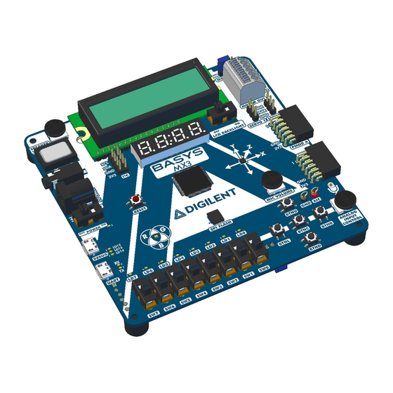
The Basys MX3 is a true MCU trainer board designed from the ground up around the teaching experience. Basys MX3 features the
PIC32MX370 from Microchip and was designed to be used with the MPLAB® X IDE. With an exhaustive set of peripherals, students gain
exposure to a wide range of embedded systems related concepts while using a professional grade tool set. Accompanied by free and open
source coursework, including seven in-depth teaching units and 15 complete labs, the Basys MX3 is a versatile MCU trainer board ideal for
teaching introductory embedded systems courses.
(https://reference.digilentinc.com/_media/reference/microprocessor/basys-mx3/basysmx3-0.png)
https://reference.digilentinc.com/reference/microprocessor/basys-mx3/reference-manual?_ga=2.68739409.1349070004.1564406803-1961480359.1...
Basys MX3 Reference Manual [Reference.Digilentinc]
1/52
Advertisement
Table of Contents

Related Manuals for Digilent Basys MX3


Summary of Contents for Digilent Basys MX3
- Page 1 Basys MX3 Reference Manual The Basys MX3 is a true MCU trainer board designed from the ground up around the teaching experience. Basys MX3 features the PIC32MX370 from Microchip and was designed to be used with the MPLAB® X IDE. With an exhaustive set of peripherals, students gain exposure to a wide range of embedded systems related concepts while using a professional grade tool set.
- Page 2 7/30/2019 Basys MX3 Reference Manual [Reference.Digilentinc] https://reference.digilentinc.com/reference/microprocessor/basys-mx3/reference-manual?_ga=2.68739409.1349070004.1564406803-1961480359.1… 2/52...
- Page 3 7/30/2019 Basys MX3 Reference Manual [Reference.Digilentinc] https://reference.digilentinc.com/reference/microprocessor/basys-mx3/reference-manual?_ga=2.68739409.1349070004.1564406803-1961480359.1… 3/52...
- Page 4 7/30/2019 Basys MX3 Reference Manual [Reference.Digilentinc] https://reference.digilentinc.com/reference/microprocessor/basys-mx3/reference-manual?_ga=2.68739409.1349070004.1564406803-1961480359.1… 4/52...
- Page 5 7/30/2019 Basys MX3 Reference Manual [Reference.Digilentinc] Download This Reference Manual Basys MX3 PDF (https://reference.digilentinc.com/_media/reference/microprocessor/basys-mx3/basys_mx3_rm.pdf) Features PIC32MX370F512L Microcontroller MIPS32® M4K® core runs up to 96 MHz () using onboard 8 MHz () oscillator 512 KB of Program Flash Memory, 12 KB of Boot Flash Memory...
- Page 6 7/30/2019 Basys MX3 Reference Manual [Reference.Digilentinc] Switches, Push-buttons, LEDs and Displays 5 Push-buttons 1 Reset button 8 Slide switches 8 LEDs 1 RGB LED () 4 Digit 7-segment display LCD () character display Audio, Motor control, and other devices Speaker with Audio Output Jack and volume control Microphone with volume control Dual H-Bridge Motor Driver for up to two 1.5 A Brushed DC Motors or one stepper motor...
-
Page 7: Software Support
The Basys MX3 is fully supported by Microchip’s MPLAB X IDE. See section 1 on Programming the Board for more information on using the Basys MX3 in MPLAB X IDE. Digilent provides a set of libraries called the Basys MX3 Library Pack that adds support for all onboard peripherals. -
Page 8: Programming Basics
7/30/2019 Basys MX3 Reference Manual [Reference.Digilentinc] 2. Select the programming tool named Basys MX3 corresponding to the board you want to program, under Licensed Debugger group. 3. Select the compiler you want to use. Another useful tool included with MPLAB X is MPLAB X IPE. This tool allows the direct programming/erasing of the microcontroller, but it does not provide an environment for writing, compiling, and debugging the code. -
Page 9: Digital Inputs And Outputs
(bit LATA1 of the register LATA is set to 1): LATAbits.LATA1 = 1; Digilent provides a set of libraries called the Basys MX3 Library Pack that addresses much of the functionality on the Basys MX3: ACL () (accelerometer) ADC () (Analog to Digital converter) - Page 10 The PIC32MX370F512L datasheet details in TABLE 12-2 (and Appendix 2 in this document) the values corresponding to each IO pin, associated to each available peripheral pin. Note that the current version of the Basys MX3 schematic (B.0) incorrectly lists RD6 and RD7 as remappable pins (RPD6 and RPD7, respectively);...
- Page 11 #pragma config FPBDIV The PBCLK divider can be set to divide by 1, 2, 4, or 8. The following example will set up the Basys MX3 for operation with a SYSCLK frequency of 80MHz and a PBCLK frequency of 80MHz. https://reference.digilentinc.com/reference/microprocessor/basys-mx3/reference-manual?_ga=2.68739409.1349070004.1564406803-1961480359.1… 11/52...
-
Page 12: Power Supplies
2. Power Supplies The Basys MX3 requires a 5-volt power source to operate. This power source can come from the Programming / Debugging USB port (J12), the USB-UART (J10), or from an external 5 Volt DC power supply that’s connected to Power Jack (J11). These three power inputs are connected together through Schottky diodes to form the primary input power network, VIN, which is used to power the onboard regulators and the majority of the onboard peripherals. - Page 13 Eight LEDs are provided, labeled LD0 – LD7 on the board (and LED0 – LED7 on the schematic), attached to eight digital IO pins. Controlling the LEDs is done by basic access to an output IO pin. Read more details in the Digital Inputs and Outputs chapter. Figure 3.1 shows the way the LEDs are electrically connected on the Basys MX3. 3.1. Connectivity Table 3.1.
-
Page 14: User Switches
LATAbits.LATA<0-7> = 0; // turn led off Library functions for using the LEDs are contained in the Basys MX3 library pack, LED () library. However, the user can easily use the LEDs without the LED () library, as presented above. - Page 15 7/30/2019 Basys MX3 Reference Manual [Reference.Digilentinc] 4.1. Connectivity Table 4.1. Switches connectivity. Label Schematic Name PIC32 Pin Pin Shared With Description RPF3/RF3 Switch 0 RPF5/PMA8/RF5 Switch 1 RPF4/PMA9/RF4 Switch 2 RPD15/RD15 Switch 3 RPD14/RD14 Switch 4 AN11/PMA12/RB11 Switch 5 CVREFOUT/AN10/RPB10/CTED11PMA13/RB10...
-
Page 16: User Buttons
7/30/2019 Basys MX3 Reference Manual [Reference.Digilentinc] Library functions for using the switches are contained in the Basys MX3 library pack, SWT library. However, the user can easily use the switches without the SWT library, as presented above. 4.3. Shared Pins As shown in the connectivity table above, SW7 driving signal is shared with the TRIG_2 signal in 2×15 Pins Debug Header. - Page 17 BTNC is shared with TRIG_1 signal in 2×15 Pins Debug Header, so it can be used to trigger events in an Analog Discovery board experiment. 6. RGB LEDs The Basys MX3 board contains one tri-color (RGB) LED (). The LED () allows the user to obtain any RGB color by configuring the R, G and B color components. https://reference.digilentinc.com/reference/microprocessor/basys-mx3/reference-manual?_ga=2.68739409.1349070004.1564406803-1961480359.…...
- Page 18 The usage of the RGB LED () is the same as controlling three separate LEDs, one for each color. Figure 6.1 shows the way the RGB LED () is electrically connected on the Basys MX3. There is one digital signal to control each color component. Using either 0 or 1 values for these signals will only give the user a limited number of colors (2 colors for each component), so most of the time this is not enough in applications using the RGB feature.
-
Page 19: Seven Segment Display
7. Seven Segment Display The Basys MX3 board contains a four-digit common anode seven-segment LED () display. Each of the four digits is composed of seven segments displaying a “figure 8” pattern and a decimal point, with an LED () embedded in each segment. Segment LEDs can be individually illuminated. - Page 20 To illuminate a segment, the anode should be driven high while the cathode is driven low. However, since the Basys MX3 uses transistors to drive enough current into the common anode point, the anode enables are inverted.
- Page 21 7/30/2019 Basys MX3 Reference Manual [Reference.Digilentinc] Please note that the two dots (situated between the middle digits) are not connected. 7.1. Connectivity Table 7.1. 7-segment connectivity. AN12/PMA11/RB12 Anode 0 pin AN13/PMA10/RB13 Anode 1 pin VREF-/CVREF-/PMA7/RA9 Anode 2 pin VREF+/CVREF+/PMA6/RA10 Anode 3 pin...
-
Page 22: Lcd Module
TRISGbits.TRISG14 = 0; //RG14 set as output 7.2. Functionality A seven segment display controller is implemented in the SSD () library of the Basys MX3 library pack. Here are some details on the implementation of the library: One array contains constant values for the segments configurations (one bit for each segment) corresponding to various digits (0-9, A-F). - Page 23 7/30/2019 Basys MX3 Reference Manual [Reference.Digilentinc] The board also provides a switch to turn on and off the LCD () display backlight, situated on the bottom right corner of the LCD () display. The LCD () display is controlled by a set of commands written to the device. Also, read commands provide the ability to read status and data.
- Page 24 7/30/2019 Basys MX3 Reference Manual [Reference.Digilentinc] 8.1. Connectivity Table 8.1. LCD () Connectivity. Name PIC32 Pin Description DISP_RS AN15/RPB15/OCFB/CTED6/PMA0/RB15 Register Select: High for Data Transfer, Low for Instruction Transfer. DISP_RW RPD5/PMRD/RD5 Read/Write signal: High for Read mode, Low for Write mode.
- Page 25 The I2C bus is an open-collector bus. Devices on the bus actively drive the signals low. The high state of the I2C signals is achieved by pull- up resistors when no device is driving the lines low. One device on the I2C bus must provide the pull-up resistors. On the Basys MX3, I2C1 has pull-up resistors attached to it.
- Page 26 Communication over the I2C is implemented in the I2C library of the Basys MX3 library pack. 10. Accelerometer Basys MX3 provides an onboard accelerometer: NXP’s MMA8652FCR1. It is a 3-Axis, 12-bit, Digital accelerometer, exposing an I2C digital interface. It is possible to use its ACL ()_INT2 () pin for raising a programmable interrupt.
-
Page 27: Serial Peripheral Interface
I2C. Communication with ACL () is implemented in the ACL () library of the Basys MX3 library pack. The ACL () library accesses I2C library for I2C functions (initialize, read and write). The accelerometer has a set of registers that can be written in order to configure the device and read in order to access the data collected by the accelerometer. -
Page 28: Flash Memory
12. Flash Memory The Basys MX3 comes with 4 MB () of onboard flash memory. The part used is the Spansion S25FL132 and is an SPI memory. More information about the SPI interface is found in the Serial Peripheral Interface section. - Page 29 (read, write) must be implemented over SPI1. The SPI1 interface must be initialized and then accessed through read and write functions. Flash communication is implemented in the SPIFLASH library of the Basys MX3 library pack. If a user wants to use the SPI flash without the SPIFLASH library, they must implement their own SPI functions.
-
Page 30: Usb - Uart Bridge
14. USB - UART bridge The Basys MX3 provides a USB to UART serial converter, via a micro-USB connector and uses UART_TX and UART_RX pins of the PIC32. These 2 pins can be mapped to implement UART4 or UART5 functionality. See Remappable pins section for more details about remapping. -
Page 31: Motor Driver
Send and receive functions over UART are implemented in the library. 14. Motor Driver The Basys MX3 features a Dual H-Bridge Motor Driver. The part used is the Texas Instruments DRV8835. It supports up to two 1.5A brushed DC motors or one stepper motor. - Page 32 7/30/2019 Basys MX3 Reference Manual [Reference.Digilentinc] Jumper Position Description VEXT The power VEXT provided from an external supply (using the VEXT pin of the MOTOR OUT connector block) is used for motors. Please read the Texas Instruments DRV8835 datasheet for more details about the motor controller.
- Page 33 PH/EN mode: Signal 2 of the DC motor B 14.2. Functionality The control of Motor module is implemented in the MOT library of the Basys MX3 library pack. Features of the implementation: Mode selection is implemented by setting the digital output MODE pin.
- Page 34 The ANSEL bit corresponding to S0_PWM should be set to 0: ANSELBbits.ANSB8 = 0; 15.2. Functionality Servo motor driver functionality is implemented in the SRV library of the Basys MX3 library pack. Implementation features include: RB8 is mapped to OC5 RPB8R = 0x0B; // 1011 = OC5 RA15 is mapped to OC4 RPA15R = 0x0B;...
- Page 35 16. IrDA Module Basys MX3 features an onboard FIR-compatible IrDA module. The part used is the ROHM Semiconductor RPM973-H11. The RPM973- H11 is a high-performance IrDA module that integrates an infrared remote control transmission function and a high-speed (4Mbps) FIR- compatible IrDA module.
-
Page 36: Audio Out
17. Audio Out The Basys MX3 contains an audio out module, controlled by the PIC32 using the digital signal A_OUT. This digital signal is PWM controlled to generate multiple values between 0 and 3.3 V. A PWM signal is a chain of pulses generated at fixed frequency, with each pulse potentially having a different width. - Page 37 The corresponding ANSEL bit should be set to 0: ANSELBbits.ANSB14 = 0; 17.2. Functionality Functionality for access to the audio module is implemented in the AUDIO library of the Basys MX3 library pack. These are the features of the implementation: The RB14 is mapped to OC1 RPB14R = 0x0C;...
- Page 38 The corresponding ANSEL bit should be set to 1: ANSELBbits.ANSB4 = 1; 18.2. Functionality The microphone usage is described through library functions in the MIC and ADC () libraries of the Basys MX3 library pack. Implementation features include: The ADC () module is initialized.
-
Page 39: Analog Input Control
0 and 3.3V using a thumbwheel potentiometer labeled ANALOG INPUT CONTROL. A pair of wire loops on the Basys MX3, labeled AIC and GND () (J8 and J14 on the schematics), can be used to measure the voltage across the potentiometer using an external tool like a multimeter or oscilloscope. - Page 40 When viewed from the end of the connector, pin 1 is the upper right pin and pin 7 is immediately below. Pin 1 is labeled on the Basys MX3 board with “1”...
- Page 41 The pins on the microcontroller and other circuits on the board are exposed and can be damaged through ESD when handling the board. Digilent Pmods can either be plugged directly into the connectors on the Basys MX3 or attached via cables. Digilent has a variety of Pmod cables available.
- Page 42 7/30/2019 Basys MX3 Reference Manual [Reference.Digilentinc] The connector is designed to match the Analog Discovery and OpenScope connectors, but the pins can be used with other tools as well. Table 21.1 below shows the signals exposed by this connector. Table 20.1. Debug header pinout.
-
Page 43: Appendix 1: Remappable Input Pins
7/30/2019 Basys MX3 Reference Manual [Reference.Digilentinc] Pin # Silk Screen Name Type Connected to / Module Analog Discovery Pin PMD0/RE0 DB0 / LCD () module Digital IO 0 RPF12/RF12 UART_TX / UART Digital IO 8 RPF0/PMD11/RF0 BTNC / TRIG_1 / User Buttons... - Page 44 7/30/2019 Basys MX3 Reference Manual [Reference.Digilentinc] Peripheral Pin [pin name]R SFR [pin name]R bits [pin name]R Value to RPn Pin Selection 0100 = RPF0 IC4R IC4R<3:0> 0101 = RPB1 0110 = RPE5 U3RX U3RXR U3RXR<3:0> 0111 = RPC13 1000 = RPB3...
-
Page 45: Appendix 2: Remappable Output Pins
7/30/2019 Basys MX3 Reference Manual [Reference.Digilentinc] Appendix 2: Remappable Output Pins RPn Port Pin RPnR SFR RPnR Value to Peripheral Selection RPD2 RPD2R 0000 = No Connect 0001 = U3TX RPG8 RPG8R 0010 = U4RTS 0011 = Reserved RPF4 RPF4R... - Page 46 7/30/2019 Basys MX3 Reference Manual [Reference.Digilentinc] RPn Port Pin RPnR SFR RPnR Value to Peripheral Selection RPA15 RPA15R RPn Port Pin RPnR SFR RPnR Value to Peripheral Selection RPD9 RPD9R 0000 = No Connect 0001 = U3RTS RPG6 RPG6R 0010 = U4TX...
-
Page 47: Appendix 3: Basys Mx3 Pinout
RPF2R Appendix 3: Basys MX3 Pinout The following table details the Basys MX3 pinout, showing the following information: Pin #, Full Pin Name: The number and the name of the microcontroller pin, as in the microcontroller datasheet pin. Peripheral: The Basys MX3 peripheral that uses this pin. - Page 48 7/30/2019 Basys MX3 Reference Manual [Reference.Digilentinc] Schematic Full Pin Name Peripheral Name Function RPE9/RE9 MOTOR BIN1 OC5/RE9 AN5/C1INA/RPB5/RB5 MOTOR BIN2 OC3/RB5 AN4/C1INB/RB4 MICROPHONE A_MIC AN4/C1INB PGED3/AN3/C2INA/RPB3/RB3 MOTOR AIN1 OC4/RB3 PGEC3/AN2/C2INB/RPB2/CTED13/RB2 POTENTIOMETER AN2/C2INB PGEC1/AN1/RPB1/CTED12/RB1 PROGRAM/DEBUG/ P32_PGC/BTNU BUTTONS PGED1/AN0/RPB0/RB0 PROGRAM/DEBUG/ P32_PGD/BTNL BUTTONS...
- Page 49 7/30/2019 Basys MX3 Reference Manual [Reference.Digilentinc] Schematic Full Pin Name Peripheral Name Function POWER GND () POWER VCC3V3 RPD14/RD14 SWITCHES RD14 RPD15/RD15 SWITCHES RD15 RPF4/PMA9/RF4 SWITCHES RPF5/PMA8/RF5 SWITCHES RPF3/RF3 SWITCHES RPF2/RF2 SPI_FLASH SPI_SI SDO1/U5TX/U RPF8/RF8 SPI_FLASH SPI_CE SS1/U1CTS/U2 RPF7/RF7 SPI_FLASH...
- Page 50 7/30/2019 Basys MX3 Reference Manual [Reference.Digilentinc] Schematic Full Pin Name Peripheral Name Function SOSCI/RPC13/RC13 PMOD JB10 INT4/U5RTS/I SOSCO/RPC14/T1CK/RC14 PMOD INT3 ()/U5CTS POWER GND () AN24/RPD1/RD1 PMOD INT1 ()/U5RX/ AN25/RPD2/RD2 RGB_LED () LED8_R OC3/RD2 AN26/RPD3/RD3 RGB_LED () LED8_B OC4/RD3 RPD12/PMD12/RD12 RGB_LED ()
- Page 51 7/30/2019 Basys MX3 Reference Manual [Reference.Digilentinc] , doc , basys- (https://reference.digilentinc.com/tag/rm?do=showtag&tag=rm) (https://reference.digilentinc.com/tag/doc?do=showtag&tag=doc) (https://reference.digilentinc.com/tag/basys-mx3?do=showtag&tag=basys-mx3) Our Partners Help Customer Info Company Info Xilinx University Technical Support Videos About Us Program Forum (https://youtube.com/user/digilentinc) (https://store.digilentinc.com/p (https://store.digilentinc.com/partners/xilinx- (https://forum.digilentinc.com) pageid=26) Reference Wiki Shipping & Returns university-program/) (https://resource.digilentinc.com/verify/faq)
- Page 52 7/30/2019 Basys MX3 Reference Manual [Reference.Digilentinc] (https://www.reddit.com/r/digilent) (https://www.linkedin.com/company/1454013) (https://www.flickr.com/photos/127815101@N07) https://reference.digilentinc.com/reference/microprocessor/basys-mx3/reference-manual?_ga=2.68739409.1349070004.1564406803-1961480359.… 52/52...
Need help?
Do you have a question about the Basys MX3 and is the answer not in the manual?
Questions and answers
I m not able to use the basys mx3 with recent version of mplabx (6.x). The debugging tool does not show in the list. U of Sherbrooke
If the Digilent Basys MX3 board does not appear in the list of debugging tools in MPLAB X version 6.x, you can try the following steps:
1. Ensure the board is connected via the DEBUG USB connector.
2. Verify that the correct device (PIC32MX370F512L) is selected during project setup.
3. Make sure all required drivers are installed for the Basys MX3 board.
4. If the tool still does not appear, manually select it under the Licensed Debugger group.
5. If unavailable, consider using MPLAB X IPE to program/erase the microcontroller, though it does not support debugging.
If the problem persists, the version of MPLAB X may not fully support the Basys MX3 debugger integration. In this case, try using a different MPLAB X version or contact support for updates.
This answer is automatically generated