Table of Contents
Advertisement
Quick Links
Cerebot MC7™ Board Reference Manual
Revised October 23, 2012
This manual applies to the Cerebot MC7 rev. F
Overview
The Cerebot MC7 board is microcontroller development board based on a Microchip® dsPIC 16-bit Digital Signal
Controller.
The Cerebot MC7 is primarily intended to be used as a controller for electro-mechanical devices such as DC
motors. The microcontroller used, a dsPIC33FJ128MC706A, is a member of a dsPIC family optimized for motor
control applications.
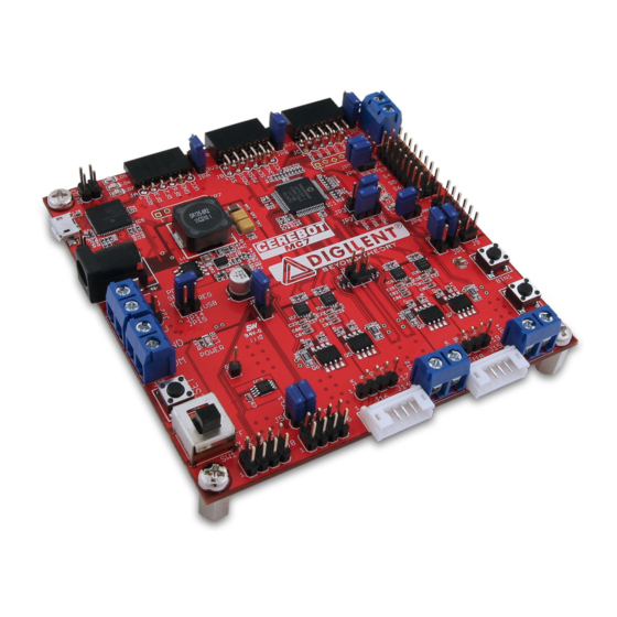
The Cerebot MC7 board.
The Cerebot MC7 provides four Half-Bridge circuits that are rated for 24V at up to 5A. Each of these Half Bridge
circuits is connected to the dsPIC A/D converter to measure voltage and current for closed loop feedback control.
These half bridges can be used to control two brushed DC motors, two bi-polar stepper motors, one brushless DC
motor, one uni-polar stepper motor. In addition, the board can be used to implement controllers for switched DC-
DC converters.
The Cerebot MC7 works with the Microchip MPLAB
and debugging support within the MPLAB IDE.
DOC#: 502-185
Other product and company names mentioned may be trademarks of their respective owners.
Features include:
•
A dsPIC33FJ128MC706A microcontroller
•
Four 24V/5A Half Bridge circuits with current
and voltage feedback and provision for over-
current interrupt
•
Power supply voltage up to 24V
5V/4A switching power supply
•
•
Integrated programming/debugging circuit
•
One CAN network interface
•
Three Pmod connectors for Digilent
peripheral module boards
Eight RC servo connectors
•
•
two I2C daisy chain connectors
•
256Kbit I2C EEPROM
•
Two push buttons and four LEDs
•
ESD protection and short circuit protection for
all I/O pins.
®
development environment and provides built in programming
Copyright Digilent, Inc. All rights reserved.
1300 Henley Court
Pullman, WA 99163
509.334.6306
www.digilentinc.com
Page 1 of 22
Advertisement
Table of Contents

Related Manuals for Digilent Cerebot MC7


Summary of Contents for Digilent Cerebot MC7
- Page 1 The Cerebot MC7 board. The Cerebot MC7 provides four Half-Bridge circuits that are rated for 24V at up to 5A. Each of these Half Bridge circuits is connected to the dsPIC A/D converter to measure voltage and current for closed loop feedback control.
-
Page 2: Functional Description
The board has a variety of input/output connection options, and is specially designed to work with the Digilent line of Pmod peripheral modules with various input and output functions. For more information, see www.digilentinc.com. -
Page 3: Board Power Supply
Microchip. The Cerebot MC7 features a flexible power supply system with a number of options for powering the board as well as powering peripheral devices connected to the board. It can be USB powered via the debug USB port, or it can be powered from an external power supply or batteries. - Page 4 5V power to power hobby servos connected to the servo connectors. This switching regulator allows single supply operation of the Cerebot MC7 board from an external power supply or battery at up to 24V DC.
- Page 5 Half-Bridge Circuits The Cerebot MC7 circuit provides four half bridges. A half bridge is made up of two stacked transistors such that the high side transistor can source current from the motor power supply and the low side transistor can sink current to the supply ground.
-
Page 6: Over-Current Detection
AN13 Over-current Detection The Cerebot MC7 provides an over-current monitoring mechanism for detecting excessive current flow through any of the half bridge circuits. Four comparators are used to monitor the current measurement from each half bridge compared to a fixed reference voltage. -
Page 7: Can Interface
There is no standard connector for use with CAN networks. The Cerebot MC7 board provides a 2x6 pin header connector, J9, for access to the CAN signals. Refer to the schematic for the Cerebot MC7 board for information on the connectors and signals. Digilent 6-pin or 2x6 to dual 6-pin cables can be used to daisy chain Digilent boards together in a CAN network. - Page 8 Each I C connector provides two positions for connecting to the I2C signals, ground and the 3.3V power supply. By using two-wire or four-wire MTE cables (available separately from Digilent) a daisy chain of multiple Cerebot MC7 boards or other I C-capable boards can be created.
-
Page 9: Pmod Connectors
On the Cerebot MC7, Pmod connector JA is a six pin connector that can be used for general purpose I/O or for connection to UART1 or SPI1. Connector JB is a twelve pin connector that can be used for general I/O and provides access to SPI2, and two external interrupts (INT2 and INT3). -
Page 10: Spi Interface
The dsPIC microcontroller used on the Cerebot MC7 provides two SPI controllers. One of these controllers (SPI2) is available for use on Pmod connector JB. This SPI controller can be used as either an SPI master or an SPI slave. The other SPI controller (SPI1) is available on Pmod connector JA. -
Page 11: Cpu Clock Source
12 User I/O Devices The Cerebot MC7 board provides two push button switches for user input and four discrete LEDs for output. The buttons, BTN1 and BTN2 are connected to I/O pins RB8 and RB14 respectively. To read the buttons, bits 8 and/or 14 of PORTB must be set as inputs by setting the corresponding bits in the TRISB register and then reading the PORTB register. -
Page 12: Appendix A: Microcontroller And Connector Pinout Tables
Cerebot MC7™ Board Reference Manual Appendix A: Microcontroller and Connector Pinout Tables MCU Port Bit to Pmod Connector Pin MCU Port Connector Signal Notes RB00 PGED3/AN0/VREF+/CN2/RB0 half bridge 1 current sense RB01 PGEC3/AN1/VREF-/CN3/RB1 half bridge 2 current sense RB02 AN2/SS1/CN4/RB2... - Page 13 Cerebot MC7™ Board Reference Manual RF00 C1RX/RF00 CAN RX RF01 C1TX/RF01 CAN TX RF02 JA-03 U1RX/SDI1/RF2 UART #1 RX RF03 JA-02 U1TX/SDO1/RF3 UART #1 TX I2C Bus #2, not shared with Pmod RF04 U2RX/SDA2/CN17/RF4 connector I2C Bus #2, not shared with Pmod...
- Page 14 Cerebot MC7™ Board Reference Manual JC-02 RD01 OC2/RD1 Servo S2 JC-03 RD02 OC3/RD2 Servo S3 JC-04 RD03 OC4/RD3 Servo S4 JC-07 RD04 OC5/IC5/CN13/RD4 Servo S5, LD1 JC-08 RD05 OC6/IC6/CN14/RD5 Servo S6, LD2 JC-09 RD06 OC7/CN15/RD6 Servo S7, LD3 JC-10 RD07...
- Page 15 Cerebot MC7™ Board Reference Manual AVSS Vcap/VDDCORE RB09 AN9/RB9 MCU Pin to Pmod Connector Pin Connector MCU Pin Signal Notes Port Bit RE05 PWM3H,RE5 PWM3H, half bridge 3 high side RE06 PWM4L/RE6 PWM4L, half bridge 4 low side RE07 PWM4H/RE7...
- Page 16 Cerebot MC7™ Board Reference Manual connector RF03 JA-02 U1TX/SDO1/RF3 UART #1 TX RF02 JA-03 U1RX/SDI1/RF2 UART #1 RX RF06 JA-04 U1RTS/SCK1/INT0/RF6 UART #1 I2C Bus #1, not shared with Pmod RG03 SDA1/RG3 connector I2C Bus #1, not shared with Pmod...
-
Page 17: Appendix B: Connector Descriptions And Jumper Settings
External Power Connector This is a 2.5mm x 5.5mm, center positive, coax power connector used to provide external power to the board. The optional Digilent 5V Switching Power Supply is connected here. Connectors J21, J22, and J24 are wired in parallel. - Page 18 5V0 supply. SPI Master/Slave Select These jumpers are used to select whether the Cerebot MC7 is configured as an SPI master device JP2 & JP3 or as an SPI slave device. See the SPI Interface section above for a discussion of how to set these jumpers.
-
Page 19: Appendix C: Measured Current Monitoring Data
Cerebot MC7™ Board Reference Manual Appendix C: Measured Current Monitoring Data Half Bridge 1: IMON1 Current Voltage (amps) (volts) 0.997 1.11 1.213 1.318 1.424 Series1 1.531 1.638 1.747 1.856 1.969 2.084 2.321 Over 5.99A Current Trip Copyright Digilent, Inc. All rights reserved. - Page 20 Cerebot MC7™ Board Reference Manual Half Bridge 2: IMON2 Current Voltage (amps) (volts) 1.028 1.139 1.242 1.348 1.45 Series1 1.556 1.662 1.77 1.88 1.99 2.106 2.223 2.344 Over Current 5.87 Trip Half Bridge 3: IMON3 Current Voltage (amps) (volts) 1.003 1.113...
- Page 21 Cerebot MC7™ Board Reference Manual Half Bridge 4: IMON4 Current Voltage (amps) (volts) 0.967 1.077 1.181 1.282 1.389 1.493 Series1 1.707 1.816 1.926 2.039 2.158 2.278 Over Current 6.15 Trip Copyright Digilent, Inc. All rights reserved. Page 21 of 22...
-
Page 22: Declaration Of Conformity
Cerebot MC7™ Board Reference Manual Declaration of Conformity In accordance with EN ISO/IEC 17050-1:2010 Manufacturers Name: Digilent, Inc. Manufacturers Address: 1300 NE Henley Court Pullman, WA 99163 U.S.A. Application of Council Directives: 2004/108/EC Standards: EN55022:2010 EN55024:2010 Product Name: Cerebot MC7...
Need help?
Do you have a question about the Cerebot MC7 and is the answer not in the manual?
Questions and answers