Table of Contents
Advertisement
Quick Links
Basys MX3™ Board Reference Manual
Revised April 21, 2017
This manual applies to the Basys MX3 rev. B
Table of Contents
Table of Contents .................................................................................................................. 1
Overview ............................................................................................................................... 5
Software Support ........................................................................................................................ 6
Coursework and Additional Materials ........................................................................................ 6
1
Programming the Board ................................................................................................. 7
1.1
Programming Tools .......................................................................................................... 7
1.2
Programming Basics ......................................................................................................... 8
1.3
Digital Inputs and Outputs ............................................................................................... 9
1.4
Remappable Pins ............................................................................................................ 10
1.5
CPU Clock Source ........................................................................................................... 11
2
Power Supplies ............................................................................................................ 12
3
User LEDs ..................................................................................................................... 13
3.1
Connectivity .................................................................................................................... 14
3.2
Functionality ................................................................................................................... 14
4
User Switches .............................................................................................................. 14
4.1
Connectivity .................................................................................................................... 15
4.2
Functionality ................................................................................................................... 16
4.3
Shared Pins ..................................................................................................................... 16
DOC#: 410-336
Other product and company names mentioned may be trademarks of their respective owners.
Copyright Digilent, Inc. All rights reserved.
1300 Henley Court
Pullman, WA 99163
509.334.6306
www.store.digilent.com
Page 1 of 56
Advertisement
Table of Contents

Related Manuals for Digilent Basys MX3


Summary of Contents for Digilent Basys MX3
-
Page 1: Table Of Contents
Pullman, WA 99163 509.334.6306 www.store.digilent.com Basys MX3™ Board Reference Manual Revised April 21, 2017 This manual applies to the Basys MX3 rev. B Table of Contents Table of Contents ........................1 Overview ..........................5 Software Support ........................6 Coursework and Additional Materials ..................6 Programming the Board .................... - Page 2 Basys MX3™ Board Reference Manual User Buttons ........................ 16 Connectivity ........................17 Functionality ........................17 Shared Pins ........................18 RGB LED ........................18 Connectivity ........................19 Functionality ........................19 6.2.1 RGB LED Implemented Using PWM ................ 19 6.2.2 RGB LED Implemented Using PDM ................. 20 Seven-segment Display ....................
- Page 3 Basys MX3™ Board Reference Manual 12.2 Functionality ....................... 31 13 UART ........................... 31 13.1 Connectivity ........................ 32 13.2 Functionality ....................... 32 14 Motor Driver ........................ 32 14.1 Connectivity ........................ 33 14.2 Functionality ....................... 35 15 Servo Headers ......................35 15.1 Connectivity ........................
- Page 4 21 Analog Discovery Debug Header ................... 45 Appendix 1: Remappable Input Pins ..................47 Appendix 2: Remappable Output Pins .................. 49 Appendix 3: Basys MX3 Pinout .................... 53 Copyright Digilent, Inc. All rights reserved. Page 4 of 56 Other product and company names mentioned may be trademarks of their respective owners.
-
Page 5: Overview
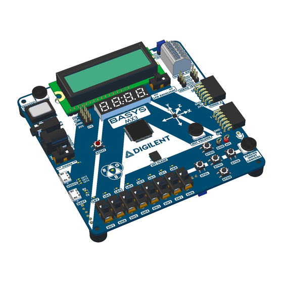
Basys MX3™ Board Reference Manual Overview The Basys MX3 is a true MCU trainer board designed from the ground up around the teaching experience. Basys MX3 features the PIC32MX370 from Microchip and was designed to be used with the MPLAB® X IDE. With an exhaustive set of peripherals, students gain exposure to a wide range of embedded systems related concepts while using a professional grade tool set. -
Page 6: Software Support
Programming the Board for more information on using the Basys MX3 in MPLAB X IDE. Digilent provides a set of libraries called the Basys MX3 Library Pack that adds support for all onboard peripherals. This library pack can be downloaded from the... -
Page 7: Programming The Board
MPLAB X IDE is the tool used to write, compile, program, and debug code running on the Basys MX3 board. Programming and debugging a program on the Basys MX3 using the MPLAB X IDE is possible using the DEBUG USB connector. -
Page 8: Programming Basics
“bits”. example (bit LATA1 of the register LATA is set to 1): LATAbits.LATA1 = 1; Digilent provides a set of libraries called the Basys MX3 Library Pack that addresses much of the functionality on the Basys MX3: ACL (accelerometer) ... -
Page 9: Digital Inputs And Outputs
Basys MX3™ Board Reference Manual This set of libraries comes with the user documentation, but this is what you must do in order to use them: Include in your project the .c and .h files corresponding to the module you want to use (for example led.c and led.h). -
Page 10: Remappable Pins
2 (and Appendix 2 in this document) the values corresponding to each IO pin, associated to each available peripheral pin. Note that the current version of the Basys MX3 schematic (B.0) incorrectly lists RD6 and RD7 as remappable pins (RPD6 and RPD7, respectively); these pins are not remappable on the PIC32MX370F512L. -
Page 11: Cpu Clock Source
FPBDIV. The PBCLK divider can be set to divide by 1, 2, 4, or 8. The following example will set up the Basys MX3 for operation with a SYSCLK frequency of 80 MHz and a PBCLK frequency of 80 MHz. -
Page 12: Power Supplies
Power Supplies The Basys MX3 requires a 5V power source to operate. This power source can come from the Programming / Debugging USB port (J12), the USB-UART (J10), or from an external 5V DC power supply that’s connected to Power Jack (J11). -
Page 13: User Leds
2A if servos are to be used. Ideally, the supply should be capable of provide 20 Watts of power (5V DC, 4A). Many suitable supplies can be purchased from Digilent or other catalog vendors. -
Page 14: Connectivity
LATAbits.LATA<0-7> = 1; // turn led on LATAbits.LATA<0-7> = 0; // turn led off Library functions for using the LEDs are contained in the Basys MX3 library pack, LED library; however, the user can easily use the LEDs without the LED library, as presented above. -
Page 15: Connectivity
Basys MX3™ Board Reference Manual Figure 4.1. Switches schematic diagram. Connectivity Schematic Label PIC32 Pin Shared Description Name With RPF3/RF3 Switch 0 RPF5/PMA8/RF5 Switch 1 RPF4/PMA9/RF4 Switch 2 RPD15/RD15 Switch 3 RPD14/RD14 Switch 4 AN11/PMA12/RB11 Switch 5 CVREFOUT/AN10/RPB10/CTED11PMA13/RB10 Switch 6... -
Page 16: Functionality
= PORTBbits.RB10; // read SW6 val = PORTBbits.RB9; // read SW7 Library functions for using the switches are contained in the Basys MX3 library pack, SWT library; however, the user can easily use the switches without the SWT library, as presented above. Shared Pins... -
Page 17: Connectivity
Basys MX3™ Board Reference Manual Figure 5.1. Button schematic diagram. The Basys MX3 also has a red button labeled RESET. This button is connected directly to the MCLR pin of the PIC32 and will trigger it to be reset. Connectivity... -
Page 18: Shared Pins
Analog Discovery board experiment. RGB LED The Basys MX3 board contains one tri-color (RGB) LED. The LED allows the user to obtain any RGB color by configuring the R, G and B color components. Figure 6.1. RGB LED schematic diagram. -
Page 19: Connectivity
Basys MX3™ Board Reference Manual There is one digital signal to control each color component. Using either 0 or 1 values for these signals will only give the user a limited number of colors (two colors for each component), so most of the time this is not enough in applications using the RGB feature. -
Page 20: Rgb Led Implemented Using Pdm
For each color, the accumulator is masked so that it only contains an 8-bit value (carry is cleared). Seven-segment Display The Basys MX3 board contains a four-digit common anode seven-segment LED display. Each of the four digits is composed of seven segments displaying a “figure 8” pattern and a decimal point with an LED embedded in each segment. - Page 21 To illuminate a segment, the anode should be driven high while the cathode is driven low; however, since the Basys MX3 uses transistors to drive enough current into the common anode point, the anode enables are inverted. Therefore, both the AN0 … AN3 and the CA … G/DP signals are driven low when active.
-
Page 22: Connectivity
Basys MX3™ Board Reference Manual A scanning display controller circuit can be used to show a 4-digit number on this display. This circuit drives the anode signals and corresponding cathode patterns of each digit in a repeating, continuous succession at an update rate that is faster than the human eye can detect. -
Page 23: Functionality
TRISDbits.TRISD13 = 0; //RD13 set as output TRISGbits.TRISG14 = 0; //RG14 set as output Functionality A seven-segment display controller is implemented in the SSD library of the Basys MX3 library pack. Here are some details on the implementation of the library: ... -
Page 24: Lcd Module
Basys MX3™ Board Reference Manual LCD Module The Basys MX3 features a basic LCD module, the Sunlike Display SD1602H with a KS0066U display controller. It displays two rows of 16 characters. It is controlled using a set of command signals (DISP_RS, DISP_R/W, DISP_EN) and 8 data signals (DB0 - DB7). -
Page 25: Connectivity
Basys MX3™ Board Reference Manual The following timing diagrams detail how write and read processes must be implemented. The essential difference is the polarity of the DISP_RW signal (0 for write and 1 for read). For more detailed timing information, refer to the KS0066U datasheet. -
Page 26: Functionality
ANSELEbits.ANSE27 = 0; // disable analog functionality on RE7 (DB7) Functionality The recommended approach to controlling the LCD module is to use the LCD library of the Basys MX3 library pack. Features implemented: Low level read and write functionality are implemented using command / data pins, according to the parallel port approach described above. -
Page 27: C Interface
C daisy chain connector provides two positions each for connecting to the I C signals, power and ground. By using two-wire or four-wire MTE cables (available separately from Digilent) a daisy chain of multiple I C-capable devices can be created. -
Page 28: Accelerometer
0x1D. Communication over the I C is implemented in the ACL library of the Basys MX3 library pack. If the user wants to use the accelerometer without the ACL library, they must implement their own I C functions. -
Page 29: Shared Pins
Basys MX3™ Board Reference Manual Please read the MMA8652FCR1 documentation for more details. 10.3 Shared Pins The Accelerometer shares the I C1 pins with other devices that can be connected using the interface connector (detailed in the C Interface section). -
Page 30: Flash Memory
SPI2 without the SPIJA library, they must define their own SPI functions. 12 Flash Memory The Basys MX3 comes with 4 MB of onboard flash memory. The part used is the Spansion S25FL132 and is an SPI memory. More information about the SPI interface is found in the Serial Peripheral Interface section. -
Page 31: Functionality
Flash communication is implemented in the SPIFLASH library of the Basys MX3 library pack. If a user wants to use the SPI flash without the SPIFLASH library, they must implement their own SPI functions. -
Page 32: Connectivity
14 Motor Driver The Basys MX3 features a Dual H-Bridge Motor Driver. The part used is the Texas Instruments DRV8835. It supports up to two 1.5A brushed DC motors or one stepper motor. The PIC32 uses 5 signals: MODE, AIN1, AIN2, BIN1, BIN2, to connect to the motor driver MODE, AIN1/APHASE, AIN2/AENBL, BIN1/BPHASE, BIN2/BENBL control pins. -
Page 33: Connectivity
Basys MX3™ Board Reference Manual Figure 14.1. Motor driver schematic diagram. The MODE signal selects one of the two operating modes: logic low selects IN/IN mode, while logic high selects PH/EN mode. When using IN/IN mode, the logical values of AIN1, AIN2, BIN1, BIN2 control the 4 command signals of a stepper motor: A1, A2, B1, B2. - Page 34 Basys MX3™ Board Reference Manual Name PIC32 pin Motor Driver pin Description logic low selects IN/IN mode MODE RPF1/PMD10/RF1 MODE logic high selects PH/EN mode IN/IN mode: Logic high sets AOUT1 high AIN1 PGED3/AN3/C2INA/RPB3/RB3 AIN1/APHASE PH/EN mode: Sets direction of H-bridge A...
-
Page 35: Functionality
Basys MX3™ Board Reference Manual 14.2 Functionality The control of Motor module is implemented in the MOT library of the Basys MX3 library pack. Features of the implementation: Mode selection is implemented by setting the digital output MODE pin. -
Page 36: Connectivity
The ANSEL bit corresponding to S0_PWM should be set to 0: ANSELBbits.ANSB8 = 0; 15.2 Functionality Servo motor driver functionality is implemented in the SRV library of the Basys MX3 library pack. Implementation features include: RB8 is mapped to OC5 RPB8R = 0x0B;... -
Page 37: Shared Pins
16 IrDA Module Basys MX3 features an onboard FIR-compatible IrDA module. The part used is the ROHM Semiconductor RPM973- H11. The RPM973-H11 is a high-performance IrDA module that integrates an infrared remote control transmission function and a high-speed (4Mbps) FIR-compatible IrDA module. It features an LED for transmitting and a PIN photo diode for receiving. -
Page 38: Functionality
TRISBbits.TRISB6 = 1; //set RB6 (IR_RX) as an input ANSELBbits.ANSB6 = 0; //disable analog functionality on RB6 (IR_RX) 16.2 Functionality The control of the IrDA module is implemented in the IrDA library of the Basys MX3 library pack. Library features include: ... -
Page 39: Audio Out
Figure 17.1. Audio out schematic diagram. The Basys MX3 contains an audio out module, controlled by the PIC32 using the digital signal A_OUT. This digital signal is PWM controlled to generate multiple values between 0 and 3.3V. A PWM signal is a chain of pulses generated at fixed frequency, with each pulse potentially having a different width. -
Page 40: Functionality
The corresponding ANSEL bit should be set to 0: ANSELBbits.ANSB14 = 0; 17.2 Functionality Functionality for access to the audio module is implemented in the AUDIO library of the Basys MX3 library pack. These are the features of the implementation: ... -
Page 41: Connectivity
The corresponding ANSEL bit should be set to 1: ANSELBbits.ANSB4 = 1; 18.2 Functionality The microphone usage is described through library functions in the MIC and ADC libraries of the Basys MX3 library pack. Implementation features include: Copyright Digilent, Inc. All rights reserved. -
Page 42: Analog Input Control
ANALOG INPUT CONTROL. A pair of wire loops on the Basys MX3, labeled AIC and GND (J8 and J14 on the schematics), can be used to measure the voltage across the potentiometer using an external tool like a multimeter or oscilloscope. -
Page 43: Functionality
When viewed from the end of the connector, pin 1 is the upper right pin and pin 7 is immediately below. Pin 1 is labeled on the Basys MX3 board with “1” and can be recognized by its squared pad (both on the main board and on the Pmod device). - Page 44 Basys MX3™ Board Reference Manual VCC GND 8 signals Pin 1 Pin 6 Pin 12 Figure 20.2. Pmod connectors: front view, as loaded on PCB. Table 20.1 summarizes the content of PMODA connector. Schematic Pmod pin PIC32 pin Label PMODA_1...
-
Page 45: Analog Discovery Debug Header
ESD when handling the board. Digilent Pmods can either be plugged directly into the connectors on the Basys MX3 or attached via cables. Digilent has a variety of Pmod cables available. - Page 46 Basys MX3™ Board Reference Manual Silk Screen Pin # Type Connected to / Module Analog Discovery pin Name DISP_R/W RPD5/PMRD/RD5 DISP_R/W / LCD module Digital IO 2 IRTX PGED2/AN7/RPB7/CTED3/RB7 IR_TX / IrDA module Digital IO 10 D_EN RPD4/PMWR/RD4 DISP_EN / LCD module...
-
Page 47: Appendix 1: Remappable Input Pins
Basys MX3™ Board Reference Manual Appendix 1: Remappable Input Pins Peripheral Pin [pin name]R SFR [pin name]R bits [pin name]R Value to RPn Pin Selection INT3 INT3R INT3R<3:0> 0000 = RPD2 0001 = RPG8 T2CK T2CKR T2CKR<3:0> 0010 = RPF4... - Page 48 Basys MX3™ Board Reference Manual 0010 = RPB8 T4CK T4CKR T4CKR<3:0> 0011 = RPB15 0100 = RPD4 0101 = RPB0 IC2R IC2R<3:0> 0110 = RPE3 0111 = RPB7 1000 = Reserved IC5R IC5R<3:0> 1001 = RPF12 1010 = RPD12 1011 = RPF8...
-
Page 49: Appendix 2: Remappable Output Pins
Basys MX3™ Board Reference Manual Appendix 2: Remappable Output Pins RPn Port Pin RPnR SFR RPnR Value to Peripheral Selection RPD2 RPD2R RPG8 RPG8R 0000 = No Connect 0001 = U3TX RPF4 RPF4R 0010 = U4RTS 0011 = Reserved 0100 = Reserved... - Page 50 Basys MX3™ Board Reference Manual 1000 = SDO1 RPD11 RPD11R 1001 = Reserved 1010 = Reserved 1011 = OC4 RPF0 RPF0R 1100 = Reserved 1101 = Reserved 1110 = Reserved RPB1 RPB1R 1111 = Reserved RPE5 RPE5R RPC13 RPC13R RPB3...
- Page 51 Basys MX3™ Board Reference Manual RPB7 RPB7R RPB2 RPB2R RPF12 RPF12R RPD12 RPD12R RPF8 RPF8R RPC3 RPC3R RPE9 RPE9R RPD9 RPD9R RPn Port Pin RPnR SFR RPnR Value to Peripheral Selection 0000 = No Connect RPD1 RPD1R 0001 = U2RTS...
- Page 52 Basys MX3™ Board Reference Manual RPC2 RPC2R RPE8 RPE8R RPF2 RPF2R Copyright Digilent, Inc. All rights reserved. Page 52 of 56 Other product and company names mentioned may be trademarks of their respective owners.
-
Page 53: Appendix 3: Basys Mx3 Pinout
Basys MX3™ Board Reference Manual Appendix 3: Basys MX3 Pinout The following table details the Basys MX3 pinout, showing the following information: Pin #, Full Pin Name: The number and the name of the microcontroller pin, as in the microcontroller datasheet pin. -
Page 54: Copyright Digilent, Inc. All Rights Reserved
Basys MX3™ Board Reference Manual Schematic Pin # Full Pin Name Peripheral Function Name PROGRAM/ PGEC1/AN1/RPB1/CTED12 P32_PGC/B DEBUG/ /RB1 BUTTONS PROGRAM/ P32_PGD/B PGED1/AN0/RPB0/RB0 DEBUG/ BUTTONS PGEC2/AN6/RPB6/RB6 IRDA IR_RX U5RX PGED2/AN7/RPB7/CTED3/ IRDA IR_TX URTX VREF-/CVREF-/PMA7/RA9 VREF+/CVREF+/PMA6/RA1 RA10 AVDD POWER VCC3V3 AVSS... -
Page 55: Copyright Digilent, Inc. All Rights Reserved
Basys MX3™ Board Reference Manual Schematic Pin # Full Pin Name Peripheral Function Name SCK1/U1RTS/U2RTS/OC1/OC2/INT RPF6/SCK1/INT0/RF6 SPI_FLASH SPI_SCK SDA1/RG3 SDA1 SCL1/RG2 SCL1 SCL2/RA2 LEDS LED2 SDA2/RA3 LEDS LED3 TDI/CTED9/RA4 LEDS LED4 TDO/RA5 LEDS LED5 POWER VCC3V3 OSC1/CLKI/RC12 CLOCK 8MHZ CRYSTAL... - Page 56 Basys MX3™ Board Reference Manual Schematic Pin # Full Pin Name Peripheral Function Name TRCLK/RA6 LEDS LED6 TRD3/CTED8/RA7 LEDS LED7 PMD0/RE0 PMD0 PMD1/RE1 PMD1 TRD2/RG14 RG14 TRD1/RG12 RG12 TRD0/RG13 RG13 AN20/PMD2/RE2 PMD2 RPE3/CTPLS/PMD3/RE3 PMD3 AN21/PMD4/RE4 PMD4 Copyright Digilent, Inc. All rights reserved.
Need help?
Do you have a question about the Basys MX3 and is the answer not in the manual?
Questions and answers