
Related Manuals for VTI Instruments EX1401


Summary of Contents for VTI Instruments EX1401
- Page 1 EX1401 16-C HANNEL SOLATED HERMOCOUPLE OLTS NSTRUMENT ’ ANUAL P/N: 82-0156-000 June 20 , 2017 VTI Instruments Corp. 2031 Main Street Irvine, CA 92614-6509 (949) 955-1894...
-
Page 3: Table Of Contents
USB Data Recording ............................. 16 End-to-End Self-test ............................16 EX1401 Specifications ............................17 EX1401 Dimensional Diagram ........................... 21 EX1401 Rack Mount Kit Dimensional Diagram ....................22 Maximizing Measurement Performance ......................22 Utilize self-test .............................. 22 Allow for cold junction thermal stabilization ....................22 Select the proper filter ........................... - Page 4 IVI Shared Components Installation (Windows Only) ................. 30 Instrument Driver Installation ........................30 Platform/LXISync Instrument Driver Installation ..................31 Network Configuration ............................31 Network Configuration Reset for EX1401 ....................32 Network Troubleshooting ........................... 32 Using Multiple Network Cards ........................33 Time Configuration ............................35 Input Connections/Wiring ..........................
- Page 5 Initializing with Multiple Instruments ........................ 81 Multiple Instrument Coordination ........................81 ..............................83 CQUISITION Data Flow ................................83 FIFO ................................... 83 Data Streaming ..............................83 Memory Streaming ............................84 Disk Streaming .............................. 84 Callback Streaming ............................84 Sampling Rates ..............................84 EX1401 Preface...
- Page 6 VTI Instruments Corp. ClockFrequency ............................85 Prescaler ................................ 85 DownsamplingFactor ............................ 85 FilterType ..............................85 SampleRate ..............................85 Span ................................85 FilterCoefficients ............................86 GroupDelay ..............................86 RecordSize ..............................86 Setting The Sample Rate ..........................86 DIO Sample Rate ............................87 Overloads and Open Transducer Detection ......................
- Page 7 9................................109 ECTION ............................. 109 NBOARD EMORY Onboard Memory and Clearing Procedure ....................... 109 A ................................110 PPENDIX .......................... 110 ULTIPLE NSTRUMENT YSTEM Overview ................................110 Master and Slave .............................. 110 Synchronization Performance ........................... 110 ................................... 113 NDEX EX1401 Preface...
-
Page 8: Certification
VTI Instruments Corp. shall not be liable for injury to property other than the goods themselves. Other than the limited warranty stated above, VTI Instruments Corp. makes no other warranties, express or implied, with respect to the quality of product beyond the description of the goods on the face of the contract. -
Page 9: Declaration Of Conformity
RODUCT ONFIGURATIONS VTI Instruments Corp. declares that the aforementioned product conforms to the requirements of the Low Voltage Directive 2014/35/EU and the EMC Directive 2014/30/EU and carries the “CE” mark accordingly. The product has been designed and manufactured according to the following specifications:... -
Page 10: General Safety Instructions
VTI Instruments Corp. ENERAL AFETY NSTRUCTIONS Review the following safety precautions to avoid bodily injury and/or damage to the product. These precautions must be observed during all phases of operation or service of this product. Failure to comply with these precautions, or with specific warnings elsewhere in this manual, violates safety standards of design, manufacture, and intended use of the product. - Page 11 The operator of this instrument is advised that if the equipment is Improper Use used in a manner not specified in this manual, the protection provided by the equipment may be impaired. Conformity is checked by inspection. EX1401 Preface...
-
Page 12: Support Resources
VTI Instruments Corp. UPPORT ESOURCES Support resources for this product are available on the Internet and at VTI Instruments customer support centers. VTI Instruments Corp. World Headquarters VTI Instruments Corp. 2031 Main Street Irvine, CA 92614-6509 Phone: (949) 955-1894 Fax: (949) 955-3041... -
Page 13: Section 1
+/- 0.05°C (20°C to 30°C operating temp.) Thermocouple accuracy is detailed in the specifications. The EX1401 is as easy-to-use as it is powerful. An integrated web page provides a convenient way to instantly verify communications and instrument functionality, while industry standard IVI drivers provide a familiar application programming interface to reduce integration and program development time. -
Page 14: Scalable For Synchronized High-Speed, High-Channel Count
The EX1401 additionally offers a front panel OTD LED for each channel that illuminates upon the recognition of a fault condition. This provides for quick and easy problem channel identification. -
Page 15: Channel Independence
Sampling Rate The EX1401 is designed for sampling speeds up to a 20 kSa/s per channel, regardless of the number of enabled channels. The lowest sampling speed is 0.000002328 Hz (approximately one sample every 5 days.) -
Page 16: Triggering
USB Data Recording The EX1401 can export acquisition data at full speed to an external USB memory device, so that it can be used as a standalone data logger. This will also be useful to keep a redundant back up of data for high reliability applications, while streaming data over the Ethernet interface. -
Page 17: Ex1401 Specifications
EX1401 S PECIFICATIONS ENERAL PECIFICATIONS UMBER OF HANNELS EX1401 16 electrically isolated and fully differential inputs NPUT OWER Input voltage 10V to 50V DC, must be isolated to 1500Vrms Power (AUX) 12 W typical, 15 W max PoE+ Power... - Page 18 VTI Instruments Corp. Type -100°C 0°C 100°C 300°C 500°C 700°C 900°C 1100°C 1400°C -200°C 1200°C ±0.30°C ±0.20°C ±0.20°C ±0.30°C ±0.30°C ±0.30°C ±0.40°C ±0.40°C -200°C 1372°C ±0.30°C ±0.30°C ±0.30°C ±0.30°C ±0.40°C ±0.40°C ±0.50°C ±0.50°C ±0.60°C T** -200°C 400°C ±0.40°C ±0.30°C ±0.20°C ±0.30°C ±0.30°C -200°C 900°C ±0.30°C ±0.20°C ±0.20°C ±0.20°C ±0.30°C ±0.30°C ±0.30°C...
- Page 19 50 Ohm series terminated with a 10k Ohm pulldown resistor 1 μs Minimum Input Pulse Width Maximum Output Frequency (CLK) 10 MHz < 0.8V > 3.5V < 0.65V @ 32 mA > 3.0 V @ 32 mA 50mA max EX1401 Introduction...
- Page 20 VTI Instruments Corp. DIO S PECIFICATIONS UMBER OF CHANNELS LECTRICAL PECIFICATIONS Maximum Input Voltage -0.5V to 5.5V, ESD protected Input Impedance Signal is pulled low by a 10k Ohm resistor 100 μs Minimum Input Pulse Width 100 μs, updated synchronously with the ADC sampling, prior to decimation Minimum Output Pulse Width <...
-
Page 21: Ex1401 Dimensional Diagram
-40 C to +70 C (MIL-PRF-28800 Class 3) Storage UMIDITY 5% – 95% (non-condensing) (MIL-PRF-28800 Class 3) LTITUDE Up to 4600 Meters, above MSL (MIL-PRF-28800 Class 3) HOCK AND IBRATION Conforms to MIL-PRF-28800 Class 3 EX1401 D IMENSIONAL IAGRAM Note: All dimensions are in inches EX1401 Introduction... -
Page 22: Ex1401 Rack Mount Kit Dimensional Diagram
ERFORMANCE This section discusses tips and procedures that can help maximize the actual performance realized with the EX1401 and aid the user in avoiding some common pitfalls associated with measurement. Utilize self-test Self-test should be conducted to check the working condition of measurement path, CJC thermistor and digital control section. -
Page 23: Choose An Appropriate Sampling Rate
For best instrument noise performance, the sampling rate should be set as low as the data collection requirements allow. For more details, see Sampling Ratein Section 3. Select proper location for installation The EX1401 unit should be located away from sources of high or low temperature, strong air currents, and high magnetic fields. Use correct wiring Best results will be achieved with the shortest and thickest thermocouple wire that the physical requirements of the application can support. -
Page 25: Section 2
EXLab Software/Manual (Optional) It also contains IVI shared components required to be installed for the device identification purpose. The LXI discovery utility provided on the CD is helpful to discover the EX1401 and other LXI devices connected in the network. -
Page 26: Location Of Connectors
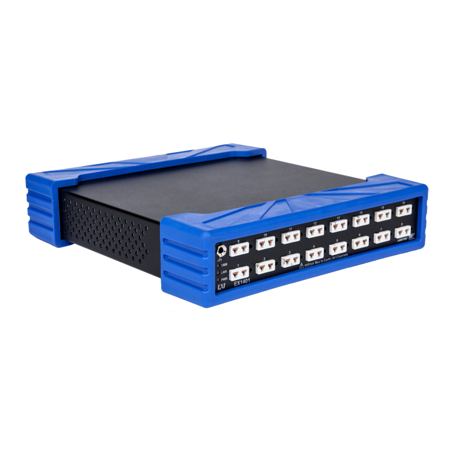
VTI Instruments Corp. OCATION OF CONNECTORS Given below are the locations of various buttons, indicators and connectors on EX1401. Earth point socket (standard Banana socket) LXI System status indicators Input connector (Mini Thermocouple Socket Cu-Cu) Open thermocouple fault indication LED... -
Page 27: Installation Options
1) Place the chassis on a protected work surface with its input connectors facing front. 2) Using a #2 Phillips screwdriver, install the rack shelf/tray on the bottom of the EX1401 using four (4) 4-40 x 3/16", Flat 82° Undercut Phillips, Black Oxide screws, as shown in below diagram. -
Page 28: Tabletop Installation Option
P AND ROUNDING The EX1401 is designed to be powered by a DC power source. It can be provided by either using a PoE+ enabled Ethernet port (which injects DC power into the network lines, such that there is no need of additional wiring), or through an external DC power adaptor. -
Page 29: Software Installation
(VTI# 53-0070-072). Do not use the banana jack on the front panel for earth grounding the EX1401. This connector is for reference only, and is not meant to be a safety ground connection. The front side connector is a standard Banana socket (ITT Pomona 3267), while the rear side connector is 10-32 size stud. -
Page 30: Ivi Shared Components Installation (Windows Only)
IVI Shared Components library (for Windows OS only) or the VTI Common Library (for Linux OS only) and the provided VTI Instruments driver. For 32-bit Windows OS, install the 32-bit driver. For Windows 7 (64-bit), Windows 8 (64-bit), and Windows 10 (64-bit), the 64-bit driver installer includes both 64-bit and 32-bit compatible drivers. -
Page 31: Platform/Lxisync Instrument Driver Installation
ETWORK ONFIGURATION By default, the EX1401 will attempt to locate a DHCP server. If one is found, the IP address assigned by the DHCP server will be assumed. Otherwise, after a timeout of 20 seconds, the unit will attempt to obtain an IP address by using Auto IP. -
Page 32: Network Configuration Reset For Ex1401
ETWORK ROUBLESHOOTING If an error occurs, when trying to discover the EX1401 you may refer to Common Issues in Section 4 If none of these resolutions help resolve the network connectivity issue, it may be necessary to change the network settings for the EX1401 and the host PC. By using the following methodology,... -
Page 33: Using Multiple Network Cards
When multiple network cards exist in a single PC, it may be necessary to define a static IP address to both the host PC NIC card that will interface with the EX1401 instrument as well as the EX1401 instrument itself. This process is only necessary if a DCHP server is not connected to the network to which the device is connected and typically occurs when the NIC is connected directly to the instrument. - Page 34 9) Set a static IP address for the NIC card by doing the following: a) Navigate to Start → Settings → Network Connections. b) Right click on the NIC card that the EX1401 mainframe is connected to and select Properties.
-
Page 35: Time Configuration
As an example, 650 feet of 24 gauge type T wire has a resistance of about 500 Ω. Against the EX1401’s typical input bias current of 7 nA, this creates a voltage error of: ... -
Page 36: Voltage Connections
Shielded wire encloses the two thermocouple wires with a low impedance conductor that should be terminated by the user to a convenient earth ground. The EX1401 provides an external ground stud that can be used for this purpose, but any earth ground point is acceptable. -
Page 37: Ection 3
ECTION ASIC PERATION NTRODUCTION This section expands on the description of the EX1401’s features and explains how to best use them. (EU) C NGINEERING ONVERSION Each EX1401 input channel can be individually configured for measuring thermocouples or voltage. The following thermocouple types are supported:... -
Page 38: Voltage Measurement Ranges
EASUREMENT ANGES The EX1401 provides ±0.01 V, ±0.10 V, ±1.0 V, and ±10.0 V voltage measurement ranges on all input channels. Channels which are configured for thermocouple inputs will use ±0.10 V range. Voltage measurement range is programmable on a per-channel basis. -
Page 39: Cold Junction Compensation (Cjc)
EMPERATURE NITS The EX1401 can output its temperature data with units of ºC or ºF. This is controlled on a global basis, such that all input channels are configured with one setting. This selection applies to input channel data only. Input channels configured for an EU conversion of voltage are unaffected by this setting. -
Page 40: Open Transducer Detection/Overload Conditions
VERLOAD ONDITIONS The EX1401 provides the ability to detect several different signal overload conditions, as well as several ways to report them. They are reported on a per-channel basis as a 32-bit mask of active conditions, via the Channel.Overload.Status property. The following bits are supported for the... -
Page 41: Led Indications
LED I NDICATIONS As an LXI standard compliant instrument, the EX1401 instrument provides multiple LED indicators on the front and rear of the instrument to indicate the power, network connectivity and synchronization status. -
Page 42: Ieee 1588 Led
Channel LED Indicators In addition to the system status indicators, the EX1401 also features a red LED for each channel on its front panel, mounted next to the mini-TC connector. The behavior of this LED can be controlled by setting the Channel.Overload.Indicator property. This is a mask with the same bit values as the... -
Page 43: Triggering
Each Input channel of Digital IO port is pulled down through 10K Ohm resistor to its ground RIGGERING The EX1401 supports a full function trigger model with a separate arm source and trigger source event structure. For a complete explanation of the trigger model, see Start, Arm, Trigger, and Alarm in Section 5. -
Page 44: Acquiring Data
In general, the acquisition and retrieval of data on the EX1401 are conducted with discrete commands that are often separated in time to a large degree. The EX1401 utilizes a 256 MB FIFO memory storage to buffer acquisition data prior to retrieval. This reading buffer is cleared upon receipt of the trigger initialize command in preparation for reading storage, and begins storing new data in a circular buffer immediately. -
Page 45: User-Defined Conversions
ISPLAY The display on the rear side of EX1401 is a 20 x 2 backlit LCD. It can display several screens that can be cycled through using the Menu button. Some screens allow you to initiate an action. This is done by holding the menu button in for several seconds. -
Page 46: Ipv4 Address
Note that the HostID portion is common to both the Local and Global addresses and so is only displayed once. IPv6 Local Subnet fe80:0000:0000:0000* IPv6 HostID 020d:3fff:fe01:1f9c* IPv6 Global Subnet* Network unavailable MAC Address MAC Address 00:0d:3f:01:1f:9c LAN Reset LAN Config Reset Hold MENU to reset EX1401 Basic Operation... -
Page 47: Self-Test
Meas: Measuring data after a trigger • Acquired Records: The number of records measured so far this measurement. • Completed Triggers: If Trigger Count is finite, the percentage of total triggers completed so far. If infinite, the number of triggers completed. EX1401 Basic Operation... -
Page 48: Usb Memory Devices
EMORY EVICES The EX1401 provides a single USB 2.0 port on its rear panel. Any USB 2.0 or earlier compatible memory device can be attached. A USB hub may also be used to attach many USB memory devices at the same time. For more information, related to standalone data logging and USB memory device... -
Page 49: Section 4
OOL WITH ELECTED Alternatively, the EX1401 may also be discovered using Internet Explorer’s Bonjour for Windows plug-in. By default, the EX1401 will first attempt to use DHCP to set its IP Address. If DHCP is not EX1401 Web Page Operation... -
Page 50: Common Issues
ENERAL PERATION When initial connection is made to the EX1401, the instrument home page, or Index, appears. This page displays instrument-specific information. This page is accessible from any other instrument page by clicking on the EX1401 web page header. The EX1401 Navigation Menu is displayed on... - Page 51 Entry: These pages display and accept changes to the configuration of the instrument. The Network Configuration page is an example of an entry page. Use of the entry-type web pages in the EX1401 are governed by a common set of operational characteristics: •...
-
Page 52: Login
To log in, simply enter the password in the given text field, and press the Submit button. By default, the EX1401 has no password. To change the password, visit the Change Password page. If the password is unknown, performing a network reset operation will reset the EX1401 to no password. -
Page 53: Index
NDEX The Index page provides the general information about the EX1401. • Model: The model number of the module. • Manufacturer: The module manufacturer. • Serial Number: The module’s serial number. • Description: A brief, user-configurable description of the module. -
Page 54: Cards
VTI Instruments Corp. ARDS The Cards page lists all modules of the EX1401. Because the EX1401 is not a modular instrument, this consists solely of one module: inst0. The following information is provided for each module: • Device: The bus and slot number of the module. Clicking on the name will launch the instrument control Soft Front Panel. -
Page 55: Soft Front Panel
If the DIO setting “Reporting Enabled” is checked, then the current input state of the DIO port will also be updated during measurement in the “7” through “0” fields. Note that the data shown EX1401 Web Page Operation... - Page 56 DIO data cannot be plotted via the SFP. But, if the DIO Reporting Enabled property is True, any DIO records associated with plotted channel data records will be included in CSV data that is downloaded via the Save Plotted Records button. EX1401 Web Page Operation...
- Page 57 EX1401 Web Page Operation...
-
Page 58: Usb Storage
Used: The amount of space used. • Use %: The percentage of total space used. Each device also includes an Eject link. Clicking this will cause the instrument to disconnect the storage device so that it can be safely removed. EX1401 Web Page Operation... -
Page 59: Network Configuration
EX1401’s network interfaces and provides the ability to modify it. • IPv4 Address Source: The IPv4 address for the EX1401 is determined by one of three sequenced mechanisms: DHCP → AutoIP → Static. If an IP address cannot be obtained with the first mechanism, it will progress to the next method. - Page 60 Subnet Mask: Defines the range of IP addresses the EX1401 will attempt to connect to directly (255.255.255.0 means match all but the last number, etc.). Gateway Address: The IP address of a server that EX1401 can use to contact IP addresses external to its network.
-
Page 61: Instrument Health
NSTRUMENT EALTH The Instrument Health Page contains information concerning the EX1401’s temperate sensors and fan controls. • Fan Mode: Off: The fan will remain off at all times. On: The fan will run at all times. Auto: The fan will turn on whenever any of the temperature sensors’ Current Value is above its Auto Fan Target. -
Page 62: Time Configuration
▪ PTP2: Precision Time Protocol Version 2 (IEEE 1588-2008) will be used to synchronize the EX1401’s time with a master clock on the network, or to act as master clock, based on the IEEE 1588 Best Master Clock algorithm. ▪... -
Page 63: Lxi Synchronization
Current Time: The current date and time of the EX1401, translated to the UTC time-base and the selected time zone. PTP Status: The current state of the PTP2 protocol within the EX1401. Offset from Master (ns): An estimate of the current error, in nanoseconds, of the EX1401’s time from that of its PTP master. -
Page 64: Lxi Identification
• LXI Module to Module Parameters LXI Domain: An 8-bit number, 0 to 255, which indicates the domain the EX1401 is using for LAN Events. All events sent by this device will include this number. Likewise, the device will only accept events that include the same LXI Domain number. -
Page 65: Blink Lan Indicator
MAC Address: Indicates the factory-assigned MAC address of the module. Gateway: The IP address of a server that EX1401 can use to contact IP addresses external to its network. DHCPEnabled: Indicates whether DHCP is enabled on the interface. -
Page 66: Change Password
HANGE ASSWORD The Change Password page allows the password to be updated. • Password: Set a new password to control access to configuring the EX1401. Setting an empty password disables password requirements. ONVOLATILE EMORY The Nonvolatile Memory web page provides the ability to securely erase the contents of the EX1401’s user-writable memory devices. -
Page 67: Upgrade
Reset: Click this button to reset the EX1401 to power-on defaults. EBOOT The Reboot web page allows the EX1401 to reboot. This operation has the same effect as power- cycling the unit – it will re-load firmware from nonvolatile memory and return to power-on defaults. -
Page 68: Section 5
EX Series and EMX Series digitizer devices provided by VTI Instruments. For a simple data acquisition application, the “Digitizer” driver may be the only driver the user needs to use. The “DSA” driver is essentially a super set of the “Digitizer” driver. In addition to the data acquisition functionalities in the “Digitizer”... -
Page 69: Drivers For Linux Os
C++ and C# (Windows only) programming language. They are installed in the Examples sub-folder under the standard IVI driver installation folder, which is usually found at C:\Program Files (x86)\IVI Foundation\IVI\Drivers\VTEXDigitizer\Examples or C:\Program Files\IVI Foundation\IVI\Drivers\VTEXDigitizer\Examples. A link to the example programs can also be found in the Start Menu. EX1401 Instrument Drivers... -
Page 70: Linux Examples
RIVER NSTRUMENTS The Digitizer driver is designed to work with many digitizer products from VTI Instruments. Not all API functions defined in the driver apply to every digitizer product, since each model has a unique feature set. Calling unsupported API functions will result in a property not supported or method not supported error. - Page 71 Supported Storage Devices Supported Not supported StreamingData Supported Supported Sync Supported Supported Temperature Supported Supported Time Supported Supported Trigger Supported Supported MaxQueueSize, QueueEnabled not MaxQueueSize, QueueEnabled not supported supported 5-1: S ABLE UPPORTED UNCTIONS IN OMMON IGITIZER EX1401 Instrument Drivers...
-
Page 72: Driver Structure
36 analog input channels, one channel group for all 32 EX1401 inputs, and one channel group for all four EMX-4350 inputs. These channel groups are named “All”, “EX1401”, and “EMX-4350”. -
Page 73: Start, Arm, Trigger, And Alarm
The predefined channel group names are “ALL” or an instrument model number such as “EX1401”. Optionally, the user can create new custom channel groups using AddChannelGroup method. When more than one instrument are in the session, the... -
Page 74: Sync
In this case, the acquired data block starts earlier than the trigger event. This is achieved by buffering the data in the instrument’s FIFO prior to the trigger event. For more information, see the Data Acquisition section. EX1401 Instrument Drivers... - Page 75 After “TriggerCount” triggers are processed, the measurement waits for the next arming condition or finishes. The Holdoff time specifies the minimum amount of time the measurement has to wait before it can be triggered again once a trigger is detected. Any trigger EX1401 Instrument Drivers...
-
Page 76: Trigger Holdoff
1000 Once initialized, the EX1401 is driven by a burst of 100 positive edge transitions at a rate of 1.5 kHz. At 1.5 kHz, the time between trigger events is 667 µs. Since this time is less than 1 ms, every other trigger event will be ignored. - Page 77 For example, if edge conditions are specified on multiple digital hardware channels, the edges must occur within 25 ns of each other to be recognized as having occurred simultaneously. EX1401 Instrument Drivers...
-
Page 78: Alarms
Period to 0 causes the alarm to fire only once. The alarm properties can only be modified when the alarm is disabled. As an extension to the LXI alarm capabilities, the EX1401 also supports “now” alarms (similar to “now” LAN events). Setting the TimeSeconds and TimeFraction properties to 0 causes the alarm to fire as soon as it is enabled. -
Page 79: Retrieving Data
ETRIEVING The Digitizer driver provides two ways to retrieve data from EX1401. By default, the acquired data is stored in the instrument’s FIFO buffer. The data in the FIFO can then be read using the standard Read method. An alternative option is to use data streaming. The streaming mechanism makes it possible to transfer data with less latency and overhead than the standard FIFO Read method;... -
Page 80: Reference Clock And Time Stamps
LAN E VENTS The EX1401 can act as an LXI device. These instruments can be synchronized to an IEEE 1588 PTP grand master clock. They can be armed or triggered by LAN events or they can generate LXI LAN events to synchronize with other LXI devices through the IVI-LXISync interface defined in the IVI driver specifications. -
Page 81: Multiple Instruments
::<slot 1>,<slot 2>,…,<slot M> ] | … Where: <address x> is the IP address or host name of the EX1401 or EMX-2500 controller (of the PXIe chassis, where EMX series cards are installed) <slot x> is the slot number identifier of the instrument in a chassis. The slot number identifier is a string such as “slot0_5”... - Page 82 IGURE OORDINATION Before enabling LAN coordination, each EX1401 and EMX-2500 controller must be configured to use PTP2 as the time source (see Time Configuration in Section 4). All devices must use the same value for the PTP Domain. They must also be configured to use the same value for LXI Domain via the web page or using the Platform driver.
-
Page 83: Data Acquisition
CQUISITION The EX1401 instruments have a dedicated A/D converter at each analog input channel. The A/D converter samples analog data at fixed frequency specified by a multiple of the ClockFrequency ). The output data rate of the ADC is F . -
Page 84: Memory Streaming
The properties in the Sampling interface configure the A/D converter and decimation filters to specify the sampling rate and frequency span of the data to be acquired. Some properties in this interface are interrelated. Changing one property value can affect the other. EX1401 Instrument Drivers... -
Page 85: Clockfrequency
SampleRate values on channels in a single instrument. For EX1401, the SampleRate is a global property and will always be the same for all channels in the same instrument. The decimation ratio of the selected filter will be set to ClockFrequency / DownsamplingFactor / SampleRate, rounded down to the next valid value for the chosen FilterType. -
Page 86: Filtercoefficients
RecordSize/SampleRate. Setting The Sample Rate There are four key properties to configure when setting the EX1401’s sample rate. These are ClockFrequency, FilterType, DownsamplingFactor, and SampleRate. ClockFrequency defines the rate at which the instruments ADCs produce data. The other properties all define how that data is digitally decimated and filtered. -
Page 87: Dio Sample Rate
DIO Sample Rate The EX1401’s DIO port can record its input state at the same rate as the analog input channels. Because this data is purely digital and binary, it cannot be decimated. All DIO data is downsampled with no filtering such that the DIO sample rate is always equal to the analog channels’... -
Page 88: Time Stamps
TATUS UPPORT TAMPS During data acquisition, the EX1401 returns timestamps along with digitized analog data. The timestamps are created based on the TimestampSource clock specified in the ReferenceOscillator interface. When IEEE 1588 synchronized time stamps are desired, the TimestampSource property must be set to ReferenceOscillatorTimestampSourceSystem. -
Page 89: Easurement Rocess
IVILXISync standard API documentation Sync and Coordination The Sync interface controls how the EX1401 synchronizes its ADCs and its timestamp counter. When a sync event occurs, all ADCs in the system are synchronized to each-other, and all data timestamp counters are reset and, if using the System Timestamp Source, synchronized to the IEEE 1588 clock. -
Page 90: Analog Front End
The EX1401 can receive an arm from the back panel trigger SMB connector by enabling the EXT arm source. Arming from DIO Lines The EX1401 can receive an arm event from the digital I/O port by enabling the DIO arm sources. EX1401 Instrument Drivers... -
Page 91: Arming From Lan Events By Other Instruments
Arming from LAN Events by Other Instruments The user, or another LXI device, can send LAN events to arm the EX1401 using the Digitizer driver. Alternatively, a LAN event can be sent to the EX1401 using the Platform driver. -
Page 92: Data Retrieval
ELAYS IN VENTS Events are an optional feature allowing the EX1401 to send notifications to the user, or other instruments, when a specified event occurs. The notification can be via LAN message, EXT trigger line, or DIO output. The user can specify an event when the measurement state is armed, triggered, finished, or when an overload condition is detected on one or more channels. -
Page 93: Where To Find More Information
Each driver comes with several useful example programs in C++ and C#. PECIFICATION NFORMATION The EX1401 conforms to many industry standards in both hardware and software architecture. Although products can be used without knowing these standards, some knowledge can be useful to take full advantage of VTI Instruments products. -
Page 95: Section 6
OGGER NTRODUCTION The EX1401 can be used as a data logger, in conjunction with an external USB disk. There are two major use cases to this feature. First, it can be used for standalone operation, where the instrument has no connectivity to host computer. Secondly, it can be used as non-volatile storage space, where the measured data will be stored during network/host computer fault. -
Page 96: Configuration Of Usb Disk
▪ Context Indicator Field - A mask indicating which items are included in Context Fields ▪ Context Fields - A list of 32-bit words comprising the data payload of the context packet EX1401 Operation of Data Logger... - Page 97 ▪ Time picoseconds lower - The lower 32 bits of the picoseconds portion of the packet timestamp ▪ Samples - A list of 32-bit integer data samples ▪ Trailer - The 32-bit VRT trailer word EX1401 Operation of Data Logger...
-
Page 99: Section 7
Each input is protected from a sustained, normal mode overvoltage condition, as long as the overvoltage does not exceed +/- 100V between the two inputs of each connector. This is done with a series resistance in each input signal along with clamping diodes. The diodes clamp outside the EX1401 Theory of Operation... -
Page 100: Programmable Gain Amplifier
All channels on the EX1401 are totally independent, but are synchronized by the same clock. Therefore, all ADCs in the system sample their analog inputs at the same time and generate output data at the same rate. -
Page 101: Thermocouple Calculations
HERMOCOUPLE ALCULATIONS There are two thermocouple type-specific calculations that are performed in the EX1401. The first calculation transforms the CJC temperature into a compensating voltage that is mathematically added to the measured input voltage. The second calculation transforms this total voltage into its final thermocouple temperature. -
Page 103: Calibration
It is recommended to allow EX1401 to warm- up for at least 60 minutes and it is also recommended to update the firmware of EX1401 instrument to the latest, prior to starting calibration process. -
Page 104: Obtain Offset Coefficients
EASUREMENT ETUP Attach the Calibration cable between the Ectron calibrator and all channels of the EX1401. Red banana plug of TC Simulator cable plugs into ‘+’ on Ectron TC Simulator Black banana plug of TC Simulator cable plugs into ‘-‘ on Ectron TC Simulator... -
Page 105: Obtain Gain Coefficients
AIN COEFFICIENTS This procedure is performed to evaluate the gain error on each channel path. All EX1401 acquisition parameters and hardware setup remain the same as previous section. Set the Ectron TC Simulator to output +10V. Initiate a measurement on the EX1401. - Page 106 In the Soft Front Panel ‘Current Full Calibration’ window, click ‘Choose File’ and select the modified calibration file, then click ‘Upload’ to copy the file to the EX1401. To verify that the file is successfully uploaded to the EX1401, you can click ‘Download’ from Note the ‘Current Full Calibration’...
-
Page 107: Obtain 2.5V Reference Voltages
BTAIN REFERENCE VOLTAGES This process is for the verification of reference voltages used within the EX1401 instrument. In the Soft Front Panel, open ‘Internal Calibration References’ window. Enable all channels by individually selecting the ‘Enabled’ checkboxes as shown in Error! Reference source not found.. -
Page 108: Save 2.5V References
If the Load By Default checkbox in the ‘User Full Calibration window is selected when the unit is reset, the EX1401 will operate from the new coefficients. If Load By Default is not selected when the unit is reset, it will operate from factory calibration coefficients saved in non-volatile memory... -
Page 109: Section 9
NBOARD EMORY AND LEARING ROCEDURE The EX1401 family of instruments contains onboard memory which stores various information about the unit as well as data acquired. This section details the memory components and provides a procedure for clearing the memory. User... -
Page 110: Appendixa
± important to note, however, that because the worst-case internal channel-to-channel phase matching of the EX1401 is ±1500 ns, this additional error will cause an offset that may dominate the low variance of IEEE 1500-2008 aware networks. e.g., Meinberg LANTIME™, Hirschmann MACH1000™... - Page 111 www.vtiinstruments.com A-1: IEEE1588 N IGURE ETWORK OPOLOGY EX10xxA Index...
-
Page 113: Index
www.vtiinstruments.com NDEX troubleshooting ..............32 NIST ITS-90 thermocouple database ......37, 45, 101 noise performance ............23, 36, 38, 39 acquiring data ................44 alarm................See LXI alarm ARM event ..............See triggering AutoIP ..................31 onboard memory ................ 109 open transducer detection ............. 14 OTD detection........ - Page 114 VTI Instruments Corp. EX1401 Index...
Need help?
Do you have a question about the EX1401 and is the answer not in the manual?
Questions and answers