Sign In
Upload
Manuals
Brands
VTI Instruments Manuals
Measuring Instruments
EX1401
VTI Instruments EX1401 Manuals
Manuals and User Guides for VTI Instruments EX1401. We have
2
VTI Instruments EX1401 manuals available for free PDF download: User Manual, Operating Instructions
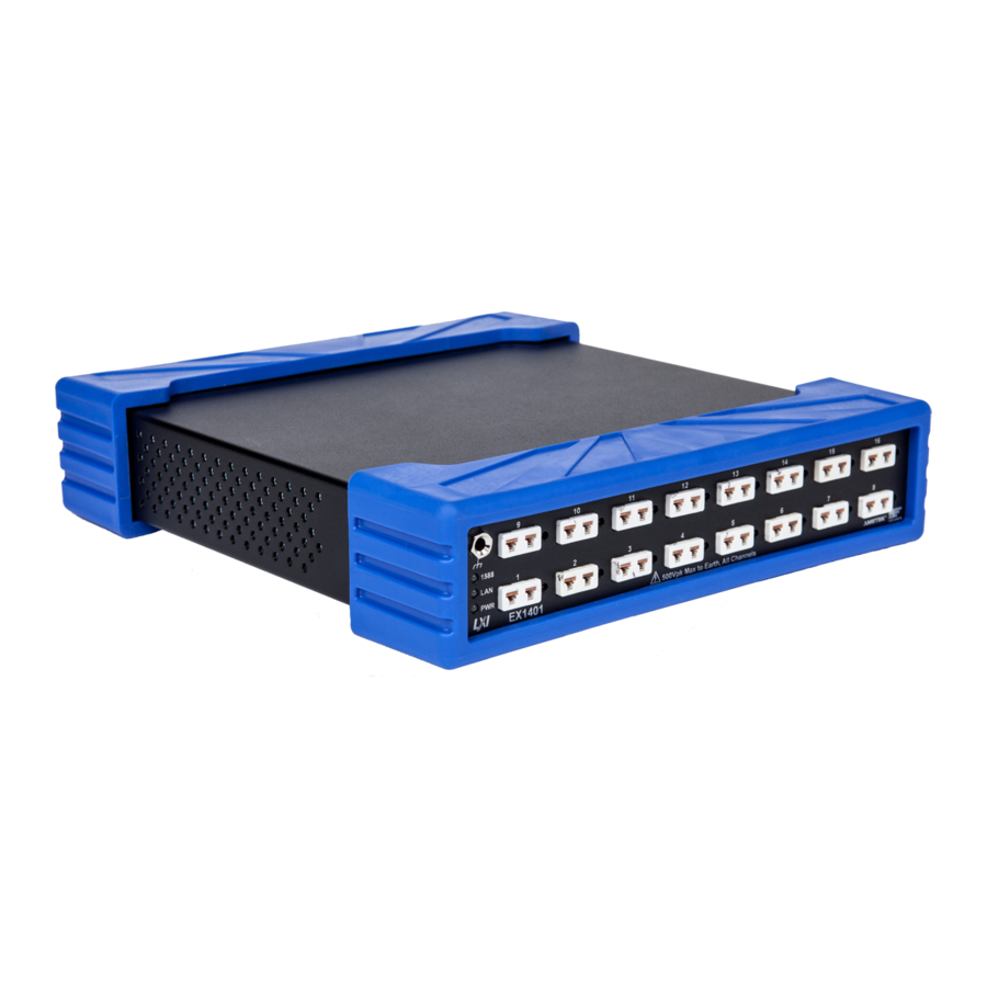
VTI Instruments EX1401 User Manual (114 pages)
16-CHANNEL ISOLATED THERMOCOUPLE/VOLTS INSTRUMENT
Brand:
VTI Instruments
| Category:
Measuring Instruments
| Size: 4 MB
Table of Contents
Table of Contents
3
Introduction
8
Certification
8
Warranty
8
Limitation of Warranty
8
Restricted Rights Legend
8
Declaration of Conformity
9
General Safety Instructions
10
Terms and Symbols
10
Warnings
10
Support Resources
12
Section 1
13
Introduction
13
Overview
13
Features
13
Combined Thermocouple and Analog Inputs
13
Scalable for Synchronized High-Speed, High-Channel Count
14
Open Thermocouple Detection (OTD)
14
Cold Junction Compensation (CJC)
14
Simplified Installation, Setup and Control
14
Channel Independence
15
Custom Thermocouple Support
15
Analog Filter
15
Digital Filter
15
Input Connectors
15
Sampling Rate
15
Digital I/O and Limits
15
Triggering
16
Multi-Function Display
16
USB Data Recording
16
End-To-End Self-Test
16
EX1401 Specifications
17
EX1401 Dimensional Diagram
21
EX1401 Rack Mount Kit Dimensional Diagram
22
Maximizing Measurement Performance
22
Utilize Self-Test
22
Allow for Cold Junction Thermal Stabilization
22
Select the Proper Filter
22
Choose an Appropriate Sampling Rate
23
Select Proper Location for Installation
23
Use Correct Wiring
23
Section 2
25
Preparation for Use
25
Unpacking EX1401
25
Installation Location
25
Location of Connectors
26
Installation Options
27
Rack-Shelf Installation Option of EX1401
27
Tabletop Installation Option
28
Warm-Up Time
28
Powering up and Grounding
28
Software Installation
29
Driver Installation
29
IVI Shared Components Installation (Windows Only)
30
Instrument Driver Installation
30
Platform/Lxisync Instrument Driver Installation
31
Network Configuration
31
Network Configuration Reset for EX1401
32
Network Troubleshooting
32
Using Multiple Network Cards
33
Time Configuration
35
Input Connections/Wiring
35
Thermocouple Connections
35
Voltage Connections
36
Ection 3
37
Basic Operation
37
Introduction
37
Engineering Unit (EU) Conversion
37
Linear Correction
37
Voltage Measurement Ranges
38
Hardware/Analog Anti-Alias Filter
38
Digital Filter
38
Measurement Range/Input Protection
38
Cold Junction Compensation (CJC)
39
Temperature Units
39
Sampling Rate/Filters/Noise Floor
39
Open Transducer Detection/Overload Conditions
40
LED Indications
41
Power LED (PWR)
41
Lan Led
41
Ieee 1588 Led
42
Leds on Network Port
42
Channel LED Indicators
42
Overload and Trigger Outputs
42
Digital I/O
42
Triggering
43
Data Format
43
Acquiring Data
44
Retrieving Data
44
User-Defined Conversions
45
LCD Display
45
Hostname
45
Ipv4 Address
46
Ipv6 Addresses
46
MAC Address
46
LAN Reset
46
Self-Test
47
Usb
47
USB Memory Devices
48
Storage Devices Apis
48
Stored Configurations
48
Data Logging
48
Section 4
49
Web
49
Introduction
49
Common Issues
50
Multiple Network Ports
50
Firewall
50
General Web
50
Login
52
Index
53
Cards
54
Soft Front Panel
55
USB Storage
58
Network Configuration
59
Instrument Health
61
Time Configuration
62
LXI Synchronization
63
LXI Identification
64
Blink LAN Indicator
65
Change Password
66
Nonvolatile Memory
66
Upgrade
67
Reset
67
Reboot
67
Section 5
68
Instrument Drivers
68
Overview
68
IVI Drivers
68
Header and Library Files
68
Drivers for Linux os
69
Header and Library Files
69
Building and Running Example Programs
69
Windows Examples
69
Linux Examples
70
Compatibility
70
Driver and Firmware Revisions
70
Driver API and Instruments
70
Driver Structure
72
Measurement
72
Channels and Channel Groups
72
Start, Arm, Trigger, and Alarm
73
Sync
74
Start
74
Arm
74
Trigger
74
Trigger Holdoff
76
Alarms
78
Retrieving Data
79
FIFO Read
79
Streaming
79
Reference Clock and Time Stamps
80
LXI and LAN Events
80
IVI Class Compliant Interfaces
80
Multiple Instruments
81
Initializing with Multiple Instruments
81
Multiple Instrument Coordination
81
Data Acquisition
83
Data Flow
83
Fifo
83
Data Streaming
83
Memory Streaming
84
Disk Streaming
84
Callback Streaming
84
Sampling Rates
84
Clockfrequency
85
Prescaler
85
Downsamplingfactor
85
Filtertype
85
Samplerate
85
Span
85
Filtercoefficients
86
Groupdelay
86
Recordsize
86
Setting the Sample Rate
86
DIO Sample Rate
87
Overloads and Open Transducer Detection
87
Time Stamps
88
Additional Data
88
Easurement Rocess
89
Measurement Setup
89
Sync and Coordination
89
Start, Arm, and Trigger
89
Sampling Parameters
89
Analog Front End
90
Measurement Initiation
90
Measurement Loop
90
Arming
90
Self-Arming
90
Arming by User's Command
90
Arming at a Certain Time Interval
90
Arming by External Pulse
90
Arming from DIO Lines
90
Arming from LAN Events by Other Instruments
91
Triggering
91
Self-Triggering
91
Triggering by User's Command
91
Triggering at a Certain Time Interval
91
Triggering by Analog Signal
91
Triggering by External Pulse
91
Triggering from DIO Lines
91
Triggering from LAN Events by Other Instruments
91
Data Retrieval
92
Pipeline Delay and Latency
92
Events
92
Where to Find more Information
93
Driver API Reference
93
Specification Information
93
Section 6
95
Operation of Data Logger
95
Introduction
95
USB Disk Selection and Preparation
95
USB Disk Insertion and Safe Removal
95
Configuration of USB Disk
96
Saving Data to USB Disk
96
HDF5 File Hierarchy
96
Section 7
99
Introduction
99
Voltage/Thermocouple Input
99
Programmable Gain Amplifier
100
Analog to Digital Conversion
100
Built in Self-Test and CJC Measurement
100
Thermocouple Calculations
101
Section 8
103
Calibration
103
Introduction
103
Required Resources
103
Equipment Needed
103
Cables Needed
103
Software Needed
103
Preliminary Setup
103
Clearing User Coefficients and Loading Defaults
103
Obtain Offset Coefficients
104
Obtain Gain Coefficients
105
Save Offset and Gain Coefficients
105
Obtain 2.5V Reference Voltages
107
Save 2.5V References
108
Custom Calibration Cable Build Instructions
108
Section 9
109
Onboard Memory
109
Onboard Memory and Clearing Procedure
109
Appendix A Multiple Instrument System
110
Overview
110
Master and Slave
110
Synchronization Performance
110
Index
113
Appendixa
110
Advertisement
VTI Instruments EX1401 Operating Instructions (2 pages)
Instructions for printing
Brand:
VTI Instruments
| Category:
Measuring Instruments
| Size: 0 MB
Table of Contents
Purpose
2
Scope
2
Instructions for Printing
2
3.1 Source File
2
3.2 Paper Size
2
3.3 Print Mode
2
3.4 Color Matching
2
3.5 Best Fit Printing
2
3.6 Margins
2
Advertisement
Related Products
VTI Instruments EX1000A
VTI Instruments EX1016A
VTI Instruments EX10SC
VTI Instruments EX1000A-51C
VTI Instruments EX1629
VTI Instruments Ametek EX1202A
VTI Instruments Ametek EX1208A
VTI Instruments AMETEK EX1044A
VTI Instruments Ametek EX1206A
VTI Instruments Ametek EX1200A Series
VTI Instruments Categories
Measuring Instruments
I/O Systems
Network Card
Switch
Network Hardware
More VTI Instruments Manuals
Login
Sign In
OR
Sign in with Facebook
Sign in with Google
Upload manual
Upload from disk
Upload from URL