
Related Manuals for Mircom OpenBAS-HV-NX10 Series


Summary of Contents for Mircom OpenBAS-HV-NX10 Series
- Page 1 OpenBAS-HV-NX10 Series Building Automation Controller and HVAC Automation Solution LT-2201 Rev. 4.4 Installation Manual October 2017...
-
Page 3: Table Of Contents
Table of Contents Introduction OpenBAS-HV-NX10 Series Building Automation Controller .......... Features ......................... Overview OpenBAS-HV-NX10 Series Components ..............Installation Parts of the Enclosure ....................Controller Board Connections ..................Installing Accessories ....................Ethernet Controllers (OpenBAS-NWK-ETH3) ..............DIP Switches ........................USB ..........................Reset and Download Buttons .................. - Page 4 List of Figures Figure 1 Parts of the enclosure ....................Figure 2 Tabs on enclosure ......................Figure 3 Lift tabs and remove circuit board .................. Figure 4 Board connections ......................Figure 5 COM ports ........................Figure 6 Location of factory-installed modules and jumpers ............Figure 7 The jumper and RS-485 module are removed from P1 ..........
- Page 5 List of Tables Table 1 OpenBAS-HV-NX10 Series Controllers ................. Table 2 OpenBAS-HV-NX10 Series Accessories ............... Table 3 OpenBAS-HV-NX10 Series Compatible Modules ............Table 4 Analog Input Wiring ......................Table 5 Wiring a 1000 Ω temperature sensor ................Table 6 Digital Input Wiring ......................
- Page 6 List of Tables 6 (45)
-
Page 7: Introduction
Automation Controller. OpenBAS-HV-NX10 Series Building Automation Controller Mircom’s OpenBAS-HV-NX10 Series building automation controller is an HVAC controller with an integrated PLC (programmable logic controller) and scheduler. It includes 18 hardware input/output points, 2 RS-485 field bus connections, USB, SPI, and I C buses. -
Page 8: Overview
Overview OpenBAS-HV-NX10 Series Components 2.1.1 Controllers Table 1 OpenBAS-HV-NX10 Series Controllers Picture Model Description HVAC controller • Integrated programmable logic controller and scheduler OpenBAS-HV-NX10P • 18 hardware input/output points • 2 RS-485 field bus connections • USB, SPI and 1²C buses... -
Page 9: Table 3 Openbas-Hv-Nx10 Series Compatible Modules
Overview Table 2 OpenBAS-HV-NX10 Series Accessories (Continued) Model Description OpenBAS-ACC-DB9 DB9 adapter OBS-ACC-32K128 128 KB plus 32 KB memory expansion OpenBAS-ACC-TE1K 1000 Ω resistive silicon temperature sensor 2.1.3 Compatible Modules Compatible modules are mounted separately from the controller. Table 3 OpenBAS-HV-NX10 Series Compatible Modules... -
Page 10: Installation
Installation Note: Installation of OpenBAS-HV-NX10 series automation controllers should be in accordance with the Canadian Electrical Code or the National Electrical Code, and comply with all local regulations. Final acceptance is subject to the Local Authority Having Jurisdiction (AHJ). Parts of the Enclosure... -
Page 11: Figure 2 Tabs On Enclosure
Installation To remove the circuit board from the enclosure Caution: Risk of Electric Shock. Disconnect the mains power and disconnect the controller from all wiring before opening the enclosure. Attention: Always hold circuit boards by the edges to prevent damage from static electricity. -
Page 12: Figure 3 Lift Tabs And Remove Circuit Board
Installation 3. Hold the circuit board with one hand, and with the other hand lift the tabs so that you can remove the circuit board from the enclosure. See Figure 3. Lift tabs and remove circuit board Circuit board Figure 3 Lift tabs and remove circuit board Attention: Be careful not to break the tabs. -
Page 13: Controller Board Connections
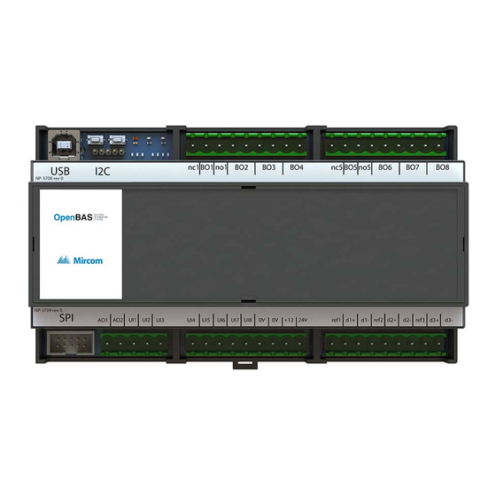
Installation Controller Board Connections Reset Download Relay Relay button connection button outputs 1-4 outputs 5-8 Connection for memory expansion or wireless receiver Connection for memory expansion or OpenBAS-HV-LCD (OpenBAS-HV-NX10L only) DIP switches Battery Connections for Connection for connection communication OpenBAS- HV-CORE2 converters display (OpenBAS-HV-NX10D... -
Page 14: Figure 5 Com Ports
Installation Connections for OpenBAS-ACC-RS485 OpenBAS-ACC-RS232 Field bus connections and connection for OpenBAS-ACC-DB9 COM1 COM2 COM3 Figure 5 COM ports For example, if OpenBAS-ACC-RS485 is installed in P1 and OpenBAS-ACC-RS232 is installed in P2, then COM1 functions as optically isolated RS-485, and COM2 functions as RS- 232. -
Page 15: Figure 6 Location Of Factory-Installed Modules And Jumpers
Installation Factory-installed RS-485 modules Jumpers Figure 6 Location of factory-installed modules and jumpers To install a communication converter 1. Open the jumper. 2. Remove the factory-installed RS-485 module. Factory-installed RS-485 Jumper module removed open Figure 7 The jumper and RS-485 module are removed from P1 15 (45) -
Page 16: Figure 8 Openbas-Acc-Rs232 Is Installed In P1
Installation 3. Install the communication converter. OpenBAS-ACC-RS232 Figure 8 OpenBAS-ACC-RS232 is installed in P1 3.3.2 Memory Expansion Card (OBS-ACC-32K128) and Wireless Receiver (OpenBAS-HV-RF433R) Connect the memory expansion cards to either one of the two terminals shown in Figure 9. They are labeled I2C and I2CB. Note: When connecting the I2C ports on 2 devices, make sure to connect pin 1 on the first device to pin 1 on the second device. -
Page 17: Ethernet Controllers (Openbas-Nwk-Eth3)
Installation Connect the OpenBAS-HV-RF433R wireless receiver to the port labeled I2C, so that it is accessible when the board is in the enclosure. Connection for wireless receiver or memory expansion card Connection for OpenBAS-HV-LCD or memory expansion card Connection for OpenBAS-HV-CORE2 SPI port for Ethernet controller... -
Page 18: Usb
Use of another battery may present a risk of fire or explosion. The battery is used only during power outages for real time clock and data retention. The Mircom part number for the battery is BT-025. Install the battery before mounting the controller. 18 (45) -
Page 19: Enclosure Dimensions
Installation To install or replace the battery 1. Disconnect the mains power and open the mains breaker. 2. Disconnect all wiring from the unit. 3. Remove the top cover as described on page 21. 4. Disconnect the old battery. 5. Dispose of the used battery promptly. Keep away from children. Do not disassemble and do not dispose of in fire. -
Page 20: 3.10 Assembly
On OpenBAS-HV-NX10D, connect the OpenBAS-HV-CORE2 display to the connection labeled N2. Make sure that the Mircom logo is the right way up. 4. Secure the display with the 4 screws. Attention: Always hold circuit boards by the edges to prevent damage from static electricity. -
Page 21: 3.11 Mounting The Enclosure
Installation 3.11 Mounting the Enclosure Attention: Mount the enclosure on a DIN rail in a UL-compliant metal box. Do not drill holes in the enclosure or modify the enclosure in any way. To mount the enclosure on a DIN rail Mount the enclosure with terminal labels the right way up and the mounting clip on the bottom. -
Page 22: Field Wiring
Field Wiring Note: Installation of OpenBAS-HV-NX10 series automation controllers must be in accordance with the Canadian Electrical Code or the National Electrical Code, and comply with all local regulations. Final acceptance is subject to the Local Authority Having Jurisdiction (AHJ). -
Page 23: Universal Inputs
Field Wiring 4.2.1 24 VDC or 24 VAC When the controller is powered from the 24V terminal, it can provide 12 VDC power to field devices through the +12 terminal. In this case, the +12 terminal can provide up to 250 mA. 0V +12 24 VAC/VDC Figure 15 Power supply - 24 VAC or 24 VDC... - Page 24 0V terminal of the controller. To ensure that the universal inputs operate correctly, follow these guidelines: • Limit the distance between the analog sensor and the controller to 10 m (30 ft). Mircom recommends shielded wire for noisy environments. •...
-
Page 25: Table 4 Analog Input Wiring
Field Wiring To use the universal inputs as analog inputs 1. Connect the appropriate analog signal to the universal input according to the diagrams below. 2. Configure the analog input type and then calibrate using the OpenBAS software. Terminal Labeling on Field Devices The positive terminal on field devices might be labeled one of the following: +PWR The negative terminal on field devices might be labeled one of the following:... - Page 26 Field Wiring Table 4 Analog Input Wiring (Continued) Type of field device Power source Wiring diagram 24 V Field Device Controller 24 V external power supply common to field 24 V powered device and controller. transducer with 1-10 Signal Power can be 24 VDC or VDC output VAC as required by the field device.
- Page 27 Field Wiring Table 4 Analog Input Wiring (Continued) Type of field device Power source Wiring diagram 24 VDC 2-wire transducer with 4- Field Device Controller 20 mA or 0-20 mA output Connect an external 250 Ω ½ Watt 1% load 24 VDC power supply resistor in parallel common to field device...
- Page 28 Field Wiring Table 4 Analog Input Wiring (Continued) Type of field device Power source Wiring diagram 3 wire transducer with 4- External power supply for 20 mA or 0-20 mA output field device (depends on Connect an external 250 field device requirements) Field Device Controller Ω...
-
Page 29: Figure 18 Measuring Vdc
Field Wiring 4.3.3 Resistive 1000 Ω Temperature Sensor For resistive temperature sensors, the corresponding DIP switch must be ON. See section 3.5 on page 17. For all other devices, the DIP switch must be OFF. Table 5 Wiring a 1000 Ω temperature sensor Type of field device Power source Wiring diagram 1000 Ω... -
Page 30: Figure 19 Digital Input Voltage Range
Field Wiring Any voltage that lies between 4.1 to 7.9 V can give ambiguous results and must be avoided. See Figure 19. Input Voltage +12V Valid Valid Uncertain ZERO region region region Figure 19 Digital input voltage range The digital inputs can be used as frequency or pulse counters with these specifications: •... -
Page 31: Analog Outputs
To ensure that analog outputs operate correctly, follow these guidelines: • Use 18 AWG stranded wire. • Limit the distance between the field device and the controller to 10 m (30 ft). Mircom recommends shielded wire for noisy environments. 31 (45) -
Page 32: Figure 20 Analog Outputs
Field Wiring • If this distance is not possible, longer wire runs with shielded wire are allowed up to 30 m (100 ft). Connect the shield to any 0V terminal on the controller, making sure to isolate the shield on the other end. Failing to do so creates ground loops. •... -
Page 33: Digital Relay Outputs
Field Wiring Table 7 Analog Output Wiring (Continued) Type of field device Wiring diagram Field Device Controller 24 V 24 VAC or VDC valve or damper with 1-10 VDC Signal control input Digital Relay Outputs Outputs 1 and 5 have common (labeled BO), normally open (labeled no), and normally closed (labeled nc) contacts. -
Page 34: Table 8 Surge Protection On Relay Outputs
Field Wiring Note: Installation of OpenBAS-HV-NX10 series automation controllers must be in accordance with the Canadian Electrical Code or the National Electrical Code, and comply with all local regulations. Final acceptance is subject to the Local Authority Having Jurisdiction (AHJ). - Page 35 Field Wiring Table 8 Surge Protection on Relay Outputs (Continued) Type of field Notes Wiring diagram device High impedance lamps such as LED lamps require a 15 kΩ Controller 120 VAC LED lamp 1W 5% resistor in parallel to 120 VAC LED the lamp to prevent current leakage.
-
Page 36: Field Bus Connections And Openbas-Acc-Db9
Note 3: To avoid intermittent communication blackouts, the isolation provided by the OpenBAS-ACC-RS485 module is highly recommended for noisy environments, and to prevent damage to the boards in extreme cases, especially if the OpenBAS-HV-NX10 series controller is inside an enclosure containing high voltage wiring. -
Page 37: Networking
Figure 24 Networking with OpenBAS-NWK-ETH3 over RS-458 4.7.1 RS-485 Details Figure 25 shows 3 controllers networked with RS-485. The list of supported protocols is in chapter 5. • 22 AWG twisted pair • Maximum length: 1219.2 m (4000 feet) • Mircom recommends shielded cable 37 (45) -
Page 38: Connections And Leds On Openbas-Hv-Hx10D
Field Wiring First controller on network Second controller on network Connect shield to Last controller chassis ground on on network one metal enclosure only Figure 25 Networking with RS-485 Connections and LEDs on OpenBAS-HV-HX10D USB connection USB connection for programming for backup Send and receive on P3... -
Page 39: Circuit Board Leds
Field Wiring Circuit Board LEDs • PWR: Is red when the unit is powered • TX and RX: Flash green to indicate communication through ports COM1 and COM2 Figure 27 LEDs 39 (45) -
Page 40: Specifications
Power Supply Protection: Resettable Fuse 1.1 A Battery: FDK Corporation ML2430 Type: lithium Nominal capacity: 100 mAh Nominal voltage: 3 V Mircom part number: BT-025 Relay Outputs 1 and 5: Voltage, current Load Form 125 VAC, 5 A General Use... - Page 41 Specifications Communication Ports: 2 RS-485 ports (3 RS-485 ports on OpenBAS-HV-NX10D) supporting the following protocols: • COM1 • BACnet/MSTP • Modbus/RTU-Slave • Modbus/RTU-Master • N2-Open • Optomux • COM2 • N2-Open • Optomux • N2/O22-master • ASCII • • COM3 (OpenBAS-HV-NX10D only) •...
-
Page 42: Warranty And Warning Information
As the only individual in contact with system users, please bring each item in this warning to the attention of the users of this Mircom System. Failure to properly inform system end-users of the circumstances in which the system might fail may result in over-reliance upon the system. - Page 43 11. Battery Failure. If the Mircom System or any device connected to the system operates from batteries it is possible for the batteries to fail. Even if the batteries have not failed, they must be fully charged, in good condition, and installed correctly.
- Page 44 20. Integrated Products. Mircom System might not function as intended if it is connected to a non-Mircom product or to a Mircom product that is deemed non-compatible with a particular Mircom System.
- Page 45 CANADA - Main Office U.S.A © Mircom 2017 25 Interchange Way 4575 Witmer Industrial Estates Printed in Canada Subject to change without prior notice Vaughan, ON L4K 5W3 Niagara Falls, NY 14305 Tel: (905) 660-4655 Tel: (905) 660-4655 www.mircomgroup.com (888) 660-4655...
Need help?
Do you have a question about the OpenBAS-HV-NX10 Series and is the answer not in the manual?
Questions and answers