
Subscribe to Our Youtube Channel
Related Manuals for Mircom OpenBAS-HV-NX4AO


Summary of Contents for Mircom OpenBAS-HV-NX4AO
- Page 1 OpenBAS-HV-NX4AO Analog Output Expansion Installation Manual LT-6632 Rev. 0 February 2018...
-
Page 3: Table Of Contents
Table of Contents Introduction OpenBAS-HV-NX4AO Analog Output Expansion ............Features ......................... Overview OpenBAS-HV-NX4AO Components ................Installation Parts of the Enclosure ....................Controller Board Connections ..................Installing Accessories ....................Voltage Input Selection Jumper ..................USB ..........................Reset and Download Buttons .................. - Page 4 Figure 11 Fit the circuit board in enclosure ..................Figure 12 Enclosure mounted on DIN rail ..................Figure 13 Enclosure mounted on DIN rail (back view) ..............Figure 14 OpenBAS-HV-NX4AO mounting orientation ..............Figure 15 Power supply connection ....................Figure 16 Analog outputs 1-4 ......................
- Page 5 List of Tables Table 1 OpenBAS-HV-NX4AO Controllers ................. Table 2 OpenBAS-HV-NX4AO Accessories ................Table 3 OpenBAS-HV-NX4AO Compatible Modules ..............Table 4 Analog Output Wiring .....................
-
Page 6: Introduction
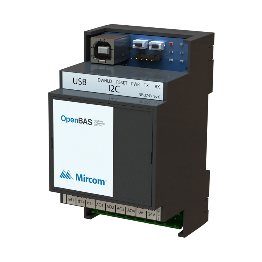
Expansion. OpenBAS-HV-NX4AO Analog Output Expansion Mircom’s OpenBAS-HV-NX4AO Analog Output Expansion is an HVAC controller with an integrated PLC (programmable logic controller) and scheduler. It includes 4 hardware analog output points, 1 RS-485 field bus connection, 1 USB port, and 1 I C bus. -
Page 7: Overview
DB9 adapter OBS-ACC-32K128 128 KB plus 32 KB memory expansion 2.1.3 Compatible Modules Compatible modules are mounted separately from the controller. Table 3 OpenBAS-HV-NX4AO Compatible Modules Model Description Ethernet controller with support for multiple protocols • 2 field bus connections OpenBAS-NWK-ETH3 •... -
Page 8: Installation
Installation Note: Installation of OpenBAS-HV-NX4AO controllers should be in accordance with the Canadian Electrical Code or the National Electrical Code, and comply with all local regulations. Final acceptance is subject to the Local Authority Having Jurisdiction (AHJ). Parts of the Enclosure... -
Page 9: Figure 2 Tabs On Enclosure
Installation To remove the circuit board from the enclosure Caution: Risk of Electric Shock. Disconnect the mains power and disconnect the controller from all wiring before opening the enclosure. Attention: Always hold circuit boards by the edges to prevent damage from static electricity. -
Page 10: Figure 3 Lift Tabs And Remove Circuit Board
Installation 2. Hold the circuit board with one hand, and with the other hand lift the tabs so that you can remove the circuit board from the enclosure. See Figure 3. Lift tabs and remove circuit board Circuit board Figure 3 Lift tabs and remove circuit board Attention: Be careful not to break the tabs. -
Page 11: Controller Board Connections
Installation Controller Board Connections Reset Download button button connection Connection for memory expansion Optional battery or wireless receiver connection Voltage input selection jumper (default position Connection for is 24 V) communication converters COM1 Analog Power outputs 1-4 Figure 4 Board connections Installing Accessories Attention: This job must be performed only by a certified technician as dangerous voltages might be present inside of the enclosure. -
Page 12: Figure 5 Com1 Port
Installation The communication converters OpenBAS-ACC-RS485 and OpenBAS-ACC-RS232 attach in place of the factory-install module shown in Figure 5 below. Factory-installed RS-485 module Jumper COM1 Figure 5 COM1 port For example, if OpenBAS-ACC-RS485 is installed, then COM1 functions as optically isolated RS-485. -
Page 13: Voltage Input Selection Jumper
To prevent damage to the controller, do not connect 24 V to the controller when the voltage input selection jumper is set to 12 VDC. The OpenBAS-HV-NX4AO can be powered by either 24 VAC/VDC or 12 VDC, but it has only one input terminal, which is labeled 24V. -
Page 14: Usb
Installation Place the jumper on pins 1 and 2 as shown in Figure 8 to power the OpenBAS-HV-NX4AO from 24 VAC/VDC. Pin 1 is marked by a dot. Figure 8 Voltage input selection jumper set for 24 V Place the jumper on pins 2 and 3 as shown in Figure 9 to power the OpenBAS-HV-NX4AO from 12 V. -
Page 15: Enclosure Dimensions
Installation To install or replace the battery 1. Disconnect the mains power and open the mains breaker. 2. Disconnect all wiring from the unit. 3. Remove the top cover as described on page 9. 4. Disconnect the old battery. 5. Dispose of the used battery promptly. Keep away from children. Do not disassemble and do not dispose of in fire. -
Page 16: Assembly
2. Snap the base onto the enclosure. Make sure that the mounting clip is on the bottom. 3. Snap the cover in place. Make sure that the Mircom logo is the right way up. Attention: Always hold circuit boards by the edges to prevent damage from static electricity. -
Page 17: 3.10 Mounting The Enclosure
Installation 3.10 Mounting the Enclosure Attention: Mount the enclosure on a DIN rail in a UL-compliant metal box. Do not drill holes in the enclosure or modify the enclosure in any way. To mount the enclosure on a DIN rail Mount the enclosure so that the terminal labels are the right way up and the mounting clip is on the bottom as shown in Figure 14. -
Page 18: Figure 14 Openbas-Hv-Nx4Ao Mounting Orientation
COM1 Power ref1 d1+ d1- AO1 AO2 AO3 Figure 14 OpenBAS-HV-NX4AO mounting orientation To remove the enclosure from the DIN rail • With your hands or with a small flathead screwdriver, pull the mounting clip to release the enclosure from the DIN rail, and carefully pull the enclosure off the DIN rail. -
Page 19: Field Wiring
12 VDC 12 VDC Figure 15 Power supply connection The OpenBAS-HV-NX4AO series controller can be powered 3 ways. • 12 Vdc, 50 mA max., or 24 Vdc, 50 mA max., or 24 Vac 50/60 Hz, 150 mA max. Set the voltage input select jumper to 12V to power the controller from 12 VDC. Set the voltage input select jumper to 24V to power the controller from 24 VAC/VDC. -
Page 20: Analog Outputs
• Use 18 AWG stranded wire. • Limit the distance between the field device and the controller to 10 m (30 ft). Mircom recommends shielded wire for noisy environments. • If this distance is not possible, longer wire runs with shielded wire are allowed up to 30 m (100 ft). -
Page 21: Figure 16 Analog Outputs
Field Wiring Figure 16 Analog outputs 1-4 Table 4 shows how to connect devices to the analog outputs. Table 4 Analog Output Wiring Type of field device Wiring diagram Field Device Controller Variable-frequency drive with 1-10 VDC input for speed control Dimmable ballast with 0- 10 VDC control input 24 V... -
Page 22: Field Bus Connection And Openbas-Acc-Db9
To avoid intermittent communication blackouts, the isolation provided by the OpenBAS-ACC- RS485 module is highly recommended for noisy environments, and to prevent damage to the boards in extreme cases, especially if the OpenBAS-HV-NX4AO controller is inside an enclosure containing high voltage wiring. -
Page 23: Circuit Board Leds
Field Wiring First controller on network Second controller on network Connect shield to Last controller chassis ground on on network one metal enclosure only Figure 18 Networking with RS-485 Circuit Board LEDs • PWR: Is red when the unit is powered •... -
Page 24: Specifications
12 Vdc, 50 mA max., or 24 Vdc, 50 mA max., or 24 Vac 50/60 Hz, 150 mA max. Optional Battery: FDK Corporation ML2430 Type: lithium Nominal capacity: 100 mAh Nominal voltage: 3 V Mircom part number: BT-025 4 Analog Outputs: Analog Output Voltage: • 0-10 VDC • 2-10 VDC •... -
Page 25: Warranty And Warning Information
As the only individual in contact with system users, please bring each item in this warning to the attention of the users of this Mircom System. Failure to properly inform system end-users of the circumstances in which the system might fail may result in over-reliance upon the system. - Page 26 11. Battery Failure. If the Mircom System or any device connected to the system operates from batteries it is possible for the batteries to fail. Even if the batteries have not failed, they must be fully charged, in good condition, and installed correctly.
- Page 27 20. Integrated Products. Mircom System might not function as intended if it is connected to a non-Mircom product or to a Mircom product that is deemed non-compatible with a particular Mircom System.
- Page 28 CANADA - Main Office U.S.A © Mircom 2018 25 Interchange Way 4575 Witmer Industrial Estates Printed in Canada Subject to change without prior notice Vaughan, ON L4K 5W3 Niagara Falls, NY 14305 Tel: (905) 660-4655 Tel: (905) 660-4655 www.mircom.com (888) 660-4655...
Need help?
Do you have a question about the OpenBAS-HV-NX4AO and is the answer not in the manual?
Questions and answers