
Related Manuals for M-system M3LU2


Summary of Contents for M-system M3LU2
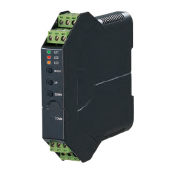
- Page 1 Space-saving Signal Conditioners M3-UNIT Series UNIVERSAL TRANSMITTER (field- and PC-configurable) Model: M3LU2 OPERATING MANUAL M3LU2 OPERATING MANUAL EM-2653-B Rev.0...
-
Page 2: Table Of Contents
3.2 CONFORMITY WITH EU DIRECTIVES ................7 3.3 ENVIRONMENT ........................7 3.4 WIRING ..........................8 3.5 HANDLING CAUTIONS ......................8 4. FEATUREs AND PREPARATION PROCEDURE OF M3LU2 ....9 4.1 FEATURES OF M3LU2 ......................9 4.2 PREPARATION PROCEDURE .....................9 5. COMPONENT IDENTIFICATION ............10 5.1 FRONT AND SIDE VIEWS ....................10 5.1.1 STATUS INDICATOR LED .................. - Page 3 12.1.5 PERFORMANCE ....................41 12.1.6 STANDARDS & APPROVALS ................42 12.1.7 I/O TYPE, MAXIMUM RANGE & ACCURACY ............42 12.1.8 CALCULATION EXAMPLES OF OVERALL ACCURACY ........44 12.2 PC CONFIGURATOR SOFTWARE ..................45 12.3 MODEL NUMBERING ......................46 12.4 EXTERNAL DIMENSIONS ....................47 M3LU2 OPERATING MANUAL EM-2653-B Rev.0...
-
Page 4: Introduction
1. INTRODUCTION Thank you for your choosing M-System. Read this manual carefully to ensure that you use the product correctly and safely. 1.1 PACKAGE Check contents of the package you received as outlined below. • Signal conditioner • Accessories I/O range and tag name label sheet... -
Page 5: Safety Precautions (Be Sure To Observe.)
Do not operate buttons with a wet hand or finger. Do not throw the unit into the fire. • Doing so may result in electric shock. • Doing so may result in rupture of the electronic component. PROHIBITION WET HANDS M3LU2 OPERATING MANUAL EM-2653-B Rev.0... - Page 6 • Doing so may result in malfunction or heating. • Doing so may result in malfunction of the unit. Use a minus screwdriver and tweezers in setting the switches. • Failure to do so may result in malfunction of the unit. M3LU2 OPERATING MANUAL EM-2653-B Rev.0...
-
Page 7: Points Of Caution
For safety, installation and maintenance of this unit must be conducted by qualified personnel. If the unit is not used in a manner not specified by M-System, the protection provided by the equipment may be impaired. 3.2 CONFORMITY WITH EU DIRECTIVEs This product conforms to the following Low Voltage and EMC Directives. -
Page 8: Wiring
• When abnormality is found such like smokes, unusual smell and abnormal noises coming from the unit, immediately cut the power supply and stop using it. M3LU2 OPERATING MANUAL EM-2653-B Rev.0... -
Page 9: Features And Preparation Procedure Of M3Lu2
4. FEATUREs AND PREPARATION PROCEDURE OF M3LU2 4.1 FEATUREs OF M3LU2 The M3LU2 is a field configurable signal transmitter using a simulator and an indicator, without a PC or a dedicated setting unit. For instance, select an input type and range with the DIP switches on the unit to set input. Then apply a desired minimum or maximum input from the simulator and press a front button to memorize the value as minimum or maximum value. -
Page 10: Component Identification
(9) Tag name label When a tag No. is specified, the unit(s) will be shipped with the tag name label put on the above position. M3LU2 OPERATING MANUAL EM-2653-B Rev.0... -
Page 11: Status Indicator Led
The output is below -15% or above +115%. Check the setting and input. Burnout The sensor or the input wiring is disconnected. Check the sensor and wiring. DIP SW error DIP SW configuration is inappropriate. Check the SW settings. System error Indicates the CPU’s communication error. M3LU2 OPERATING MANUAL EM-2653-B Rev.0... - Page 12 Input ranging Fine zero adjustment Output ranging Fine span adjustment NOTE In the I/O ranging and fine adjustments using the PC Configurator Software (model: M3LUCFG), the LEDs are not ac- cording to the above tables. M3LU2 OPERATING MANUAL EM-2653-B Rev.0...
-
Page 13: Internal View
(1) SW1 Sets output type. (2) SW2 Sets wires, cold junction compensation, burnout, front control button lock and output type. (3) SW3 Sets input type, sensor type and configuration mode. (4) JP2 Sets input type. M3LU2 OPERATING MANUAL EM-2653-B Rev.0... -
Page 14: How To Open The Cover
• Be sure to close the cover after setting. • Be careful not to get your hand or finger caught in the cover. • Do not force the cover closed. Doing so may result in damage of the electronic components. M3LU2 OPERATING MANUAL EM-2653-B Rev.0... -
Page 15: Dip Switch Configuration
• Use tweezers or longnose pliers to switch the JP2. • Use a minus screwdriver with the blade edge 0.8 mm (0.03”) to set the DIP switches. • Do not touch other electronic components except for the JP2 and DIP switches. M3LU2 OPERATING MANUAL EM-2653-B Rev.0... -
Page 16: Configuration Mode
With the model M3LU2-x/A, select the configuration mode (configuration method of I/O specifications), DIP SW configura- tion or PC configuration, as shown in the following table. With the model M3LU2-x/B, turn the SW3-8 OFF. DIP SW configuration: sets I/O specifications with the DIP switches inside the cover and the front control buttons. - Page 17 SW3-1 (PR) K (CA) E (CRC) J (IC) T (CC) B (RH) C (WRe 5-26) P (Platinel II) • Burnout BURNOUT SW2-5 SW2-4 No burnout Upscale Downscale • Cold junction compensation COLD JUNCTION COMPENSATION SW2-3 Enable Disable M3LU2 OPERATING MANUAL EM-2653-B Rev.0...
- Page 18 Pt 50 Ω (JIS ’81) JPt 100 (JIS ’89) Ni 100 Ni 120 Ni 508.4 Ω Ni-Fe 604 Cu 10 @25°C • Burnout BURNOUT SW2-5 SW2-4 No burnout Upscale Downscale • RTD wires WIRES SW2-2 SW2-1 2-wire 3-wire 4-wire M3LU2 OPERATING MANUAL EM-2653-B Rev.0...
- Page 19 SW3-1 (TOTAL RESISTANCE) 2500 to 4000 Ω 1200 to 2500 Ω 600 to 1200 Ω 300 to 600 Ω 150 to 300 Ω 80 to 150 Ω • Burnout BURNOUT SW2-5 SW2-4 No burnout Upscale Downscale M3LU2 OPERATING MANUAL EM-2653-B Rev.0...
-
Page 20: Output Type
• DC voltage output (wide spans) [maximum range: -10 to +10 V DC] SW1-4 SW1-3 SW1-2 SW1-1 7.2.5 FRONT CONTROL BUTTON LOCK You can lock the button operation on the front panel to prevent inadvertent operation. LOCK SW2-6 Unlock Lock M3LU2 OPERATING MANUAL EM-2653-B Rev.0... -
Page 21: Wiring
Ground the input shield to the most stable earth to prevent noise troubles. • Do not connect anything to unused terminals. • M-System offers a series of lightning surge protectors for protection against induced lightning surges. Please con- tact M-System to choose appropriate models. - Page 22 • Installation Push the terminal block until it clicks into place. NOTE Match the terminal numbers of the terminal blocks with those indicated on the trans- mitter body in installing the blocks (figure on the right). M3LU2 OPERATING MANUAL EM-2653-B Rev.0...
-
Page 23: Terminal Assignment
5. CJC sensor (model: CJM) • Do not use a ferrule with insulating sleeve. • Insert a wire under the CJC sensor (figure on the right). 8.3 TERMINAL AssIGNMENT Power Output signal Input signal M3LU2 OPERATING MANUAL EM-2653-B Rev.0... -
Page 24: Terminal Connections
Maximum range: -10 to +10 V DC Maximum range: -1000 to +1000m V DC DC current DC voltage (V) DC voltage (mV) Ground Ground Ground (resistance (resistance (resistance 100 ohms or less) 100 ohms or less) 100 ohms or less) M3LU2 OPERATING MANUAL EM-2653-B Rev.0... - Page 25 • The leadwire resistance including internal resistance such like a lightning surge protector and a barrier must be maxi- mum 20 Ω per wire. • The excitation is 0.3 mA. Use a RTD with excitation 0.3 mA or more. M3LU2 OPERATING MANUAL EM-2653-B Rev.0...
-
Page 26: Wiring Output
9 to 36 V DC, approx. 3 W DC power AC power AC power DC power • Be aware that the AC power and DC power connect to different terminals. • For DC power, confirm the polarity. M3LU2 OPERATING MANUAL EM-2653-B Rev.0... -
Page 27: Installation
DIN Rail 35mm wide Spring Loaded DIN Rail Adaptor ■ REMOVAL Push down the DIN rail adaptor utilizing a minus screwdriver and pull. DIN Rail 35mm wide Spring Loaded DIN Rail Adaptor M3LU2 OPERATING MANUAL EM-2653-B Rev.0... -
Page 28: Calibration
10. CALIBRATION ‘Calibration’ means I/O ranging or output fine adjustments using the front control buttons. M-System’s ‘One-Step-Cal’ cali- bration technique realizes automatic I/O ranging and adjustment. This chapter describes flow and operation procedure of the calibration. You can also carry out the calibration using the PC Configurator Software (model: M3LUCFG). For detailed information, refer to the M3LUCFG users manual. -
Page 29: Input & Output Ranging
■ PREPARATION Mount the DIP-SW-configured M3LU2 on to a DIN rail. Connect the M3LU2 to a simulator and a multimeter and to a power source according to the terminal connections. ■ INPUT RANGING • In the Input Ranging Mode, apply the desired minimum input level from the simulator and hold down DOWN button until the LD1 blinks and then turns OFF. - Page 30 • There is no stated order of setting 0% and 100% levels or no limitations of entering values for multiple times within one step of the Ranging Mode. • Signal level is not stored when UP or DOWN button is released before the LD1 turns OFF. M3LU2 OPERATING MANUAL EM-2653-B Rev.0...
-
Page 31: Maximum Range, Minimum Span And Default Value Of Input
-200 to +600 -328 to +1112 -328 to +1112 -200 to +900 -200 to +900 -328 to +1652 -328 to +1652 P (Platinel II) 0 to 1395 0 to 1395 32 to 2543 32 to 2543 M3LU2 OPERATING MANUAL EM-2653-B Rev.0... -
Page 32: Maximum Range, Minimum Span And Default Value Of Output
DEFAULT VALUE -2.5 to +2.5 V DC 250 mV 0 to 1 V DC 10.2.3.3 DC voltage output (wide spans) MAXIMUM RANGE MINIMUM SPAN DEFAULT VALUE -10 to +10 V DC 1 to 5 V DC M3LU2 OPERATING MANUAL EM-2653-B Rev.0... -
Page 33: Operation Procedure Of I/O Ranging
• Hold down UP button, and the LD1 red LED blinks in approx. 2 sec. and then turns OFF in approx. 2 sec. • The LD1 turning OFF means completion of 100% input ranging. Hold down UP button until the LD1 turns OFF. • Skip to the next procedure when 100% input ranging is not necessary. M3LU2 OPERATING MANUAL EM-2653-B Rev.0... - Page 34 • Hold down UP button, and the LD1 red LED blinks in approx. 2 sec. and then turns OFF in approx. 2 sec. • The LD1 turning OFF means completion of 100% output ranging. Hold down UP button until the LD1 turns OFF. • Skip to the next procedure when 100% output ranging is not necessary. M3LU2 OPERATING MANUAL EM-2653-B Rev.0...
- Page 35 Red ON blinking Red blinking Press once • Press MODE button once to return to the RUN mode. • The LD3 turns OFF and the LD1 green LED is ON (DIP SW configuration) or blinking (PC configuration). M3LU2 OPERATING MANUAL EM-2653-B Rev.0...
-
Page 36: Fine Adjustment Mode
DIP switch setting (SW2-6 OFF). Note that M-System does not warrant the adjustments by the customer. Each time the adjustment is performed, signal level is overwritten and is stored even when the power is off. -
Page 37: Operation Procedure Of Fine Adjustment
Green blinking Green blinking Press once • Press MODE button once to go on to the Fine Span Adjustment Mode. • The LD2 turns OFF and the LD3 green LED starts blinking indicating the Fine Span Adjustment Mode. M3LU2 OPERATING MANUAL EM-2653-B Rev.0... - Page 38 Red ON bllinking Green blinking Press once • Press MODE button once to return to the RUN Mode. • The LD3 turns OFF and the LD1 green LED is ON (DIP SW configuration) or blinking (PC configuration). M3LU2 OPERATING MANUAL EM-2653-B Rev.0...
-
Page 39: Checking, Maintenance, Initialization Of Parameters
(3) Wait until green LED blinks at the LD1, LD2 and LD3. (4) Turn off the power, open the cover and reset the SW2-1 and SW2-2 to the previous position. (5) Close the cover and turn on the power again. M3LU2 OPERATING MANUAL EM-2653-B Rev.0... -
Page 40: Appendices
Maximum range: 0 to 4000 Ω Allowable leadwire resistance: max. 20 Ω per wire Minimum span: 10 Ω Potentiometer Excitation: ≤ 0.3 mA Maximum range: refer to Table 5 Allowable leadwire resistance: max. 20 Ω per wire Minimum span: 2% M3LU2 OPERATING MANUAL EM-2653-B Rev.0... -
Page 41: Output Specifications
Burnout response ≤ 10 sec. Line voltage effect ±0.1% over voltage range Insulation resistance ≥ 100 MΩ with 500 V DC Dielectric strength 2000 V AC @ 1 minute (input to output to power to ground) M3LU2 OPERATING MANUAL EM-2653-B Rev.0... -
Page 42: Standards & Approvals
-328 to +1652 P (Platinel II) 0 to 1395 ±0.25 0 to 1395 32 to 2543 ±0.45 32 to 2543 *2 [Accuracy + Cold Junction Compensation Error 1.0°C (1.8°F)] or ±0.1% of span, whichever is greater. M3LU2 OPERATING MANUAL EM-2653-B Rev.0... - Page 43 -3 to +3 V DC -10 to +10 V DC -11.5 to +11.5 V DC *6 For current output, overall accuracy degrades another 0.1% with spans ≤ 2 mA. *7 Negative overrange current below 0 mA is not available. M3LU2 OPERATING MANUAL EM-2653-B Rev.0...
-
Page 44: Calculation Examples Of Overall Accuracy
(2) 30 to 80 Ω (total resistance 100 Ω) Absolute value accuracy [Table 5]: 0.1 Ω 0.1 Ω ÷ (80 Ω – 30 Ω) × 100 = 0.2% > 0.1% ➠ Overall accuracy = ±0.2% of span M3LU2 OPERATING MANUAL EM-2653-B Rev.0... -
Page 45: Pc Configurator Software
RS-232-C MCN-CON COP-US The PC Configurator Software is freely downloadable at M-System’s web site (http://www.m-system.co.jp/). Software download model No.: M3CFG ■ I/O CONFIGURATION The following table shows configurable items with the PC Configurator Software. For detailed information on the PC con- figuration, refer to the M3LUCFG users manual (EM-9197-A). -
Page 46: Model Numbering
B: Field configurable [3] OPTIONs blank: none /Q: With options (specify the specification) sPECIFICATIONs OF OPTION: Q COATING (For the detail, refer to M-System’s web site.) /C01: Silicone coating /C02: Polyurethane coating /C03: Rubber coating M3LU2 OPERATING MANUAL EM-2653-B Rev.0... -
Page 47: External Dimensions
(inch) 10 11 12 DIN RAIL 35mm wide 110.5 (4.35) [5 (.20)] CJC SENSOR 18 (.71) (model: CJM) • When mounting, no extra space is needed between units * Used only with a thermocouple input M3LU2 OPERATING MANUAL EM-2653-B Rev.0...
Need help?
Do you have a question about the M3LU2 and is the answer not in the manual?
Questions and answers