Table of Contents
Advertisement
Quick Links
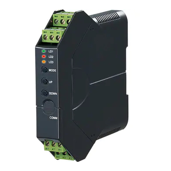
INSTRUCTION MANUAL
RTD TRANSMITTER
(field- and PC-configurable)
BEFORE USE ....
Thank you for choosing M-System. Before use, please check
contents of the package you received as outlined below.
If you have any problems or questions with the product,
please contact M-System's Sales Office or representatives.
■ PACKAGE INCLUDES:
Signal conditioner ...............................................................(1)
I/O range and tag name label sheet ...................................(1)
■ MODEL NO.
Confirm Model No. marking on the product to be exactly
what you ordered.
■ INSTRUCTION MANUAL
This manual describes necessary points of caution when
you use this product, including installation, connection and
basic maintenance procedures. For detailed information,
refer to the operating manual (EM-2662-B).
The M3LR with Option A is programmable using the PC
configurator software. For detailed information on the PC
configuration, refer to the M3LRCFG instruction manual.
The M3LRCFG PC Configurator Software and operating
manual are downloadable at M-System's web site: http://
www.m-system.co.jp.
POINTS OF CAUTION
■ CONFORMITY WITH UL
• This equipment is suitable for use in a Pollution Degree
2 environment.
• DO NOT connect the RTD to circuits greater than 30Vrms
and 42.4Vpeak or 60V DC.
• This equipment is to be used with the maximum operat-
ing voltage 30Vrms and 42.4Vpeak or 60V DC.
• The equipment must be mounted inside a suitable fire
enclosure.
• Operating temperature: -25 to +55°C (-13 to +131°F)
■ CONFORMITY WITH EU DIRECTIVES
• The equipment must be mounted inside a panel.
• Insert noise filters for the power source, input and output
connected to the unit. COSEL Model NAC-04-472, TDK
Model ZCAT 3035-1330 or equivalent is recommended.
• The actual installation environments such as panel con-
figurations, connected devices, connected wires, may af-
fect the protection level of this unit when it is integrated
in a panel system. The user may have to review the CE
requirements in regard to the whole system and employ
additional protective measures to ensure the CE conform-
ity.
• Install lightning surge protectors for those wires connect-
ed to remote locations.
5-2-55, Minamitsumori, Nishinari-ku, Osaka 557-0063 JAPAN
Phone: +81(6)6659-8201 Fax: +81(6)6659-8510 E-mail: info@m-system.co.jp
MODEL
■ POWER INPUT RATING & OPERATIONAL RANGE
• Locate the power input rating marked on the product and
confirm its operational range as indicated below:
10 – 32V DC rating: 9 – 36V, approx. 3W
■ GENERAL PRECAUTION
• Before you remove the unit or mount it, turn off the power
supply and input signal for safety.
■ ENVIRONMENT
• Indoor use.
• When heavy dust or metal particles are present in the
air, install the unit inside proper housing with sufficient
ventilation.
• Do not install the unit where it is subjected to continuous
vibration. Do not subject the unit to physical impact.
• Environmental temperature must be within -25 to +65°C
(-13 to +149°F) with relative humidity within 0 to 95%
RH in order to ensure adequate life span and operation.
• Be sure that the ventilation slits are not covered with ca-
bles, etc.
■ WIRING
• Do not install cables close to noise sources (relay drive
cable, high frequency line, etc.).
• Do not bind these cables together with those in which
noises are present. Do not install them in the same duct.
■ AND ....
• The unit is designed to function as soon as power is sup-
plied, however, a warm up for 10 minutes is required for
satisfying complete performance described in the data
sheet.
LIGHTNING SURGE PROTECTION
M-System offers a series of lightning surge protector for
protection against induced lightning surges. Please contact
M-System to choose appropriate models.
M3LR
EM-2662-A Rev.2 P. 1 / 8
Advertisement
Table of Contents

Related Manuals for M-system M3LR


Summary of Contents for M-system M3LR
- Page 1 • Be sure that the ventilation slits are not covered with ca- refer to the operating manual (EM-2662-B). bles, etc. The M3LR with Option A is programmable using the PC configurator software. For detailed information on the PC ■ WIRING configuration, refer to the M3LRCFG instruction manual.
- Page 2 EM-2662-A Rev.2 P. 2 / 8 5-2-55, Minamitsumori, Nishinari-ku, Osaka 557-0063 JAPAN Phone: +81(6)6659-8201 Fax: +81(6)6659-8510 E-mail: info@m-system.co.jp...
- Page 3 AI 1,5-8BK 1.0 to 1.5 mm • Expose wire conductors by 8 mm (0.31”). Wire exposure Recommended ferruled wire 8 mm 8 mm EM-2662-A Rev.2 P. 3 / 8 5-2-55, Minamitsumori, Nishinari-ku, Osaka 557-0063 JAPAN Phone: +81(6)6659-8201 Fax: +81(6)6659-8510 E-mail: info@m-system.co.jp...
- Page 4 LOCK SW2-1 PC Configuration is not disabled when the front control button func- No burnout Unlock Upscale tion is locked. Lock Downscale EM-2662-A Rev.2 P. 4 / 8 5-2-55, Minamitsumori, Nishinari-ku, Osaka 557-0063 JAPAN Phone: +81(6)6659-8201 Fax: +81(6)6659-8510 E-mail: info@m-system.co.jp...
- Page 5 250 mV -2.5 to +2.5 V -3 to +3 V DC Voltage, Wide Spans -10 to +10 V -11.5 to +11.5 V EM-2662-A Rev.2 P. 5 / 8 5-2-55, Minamitsumori, Nishinari-ku, Osaka 557-0063 JAPAN Phone: +81(6)6659-8201 Fax: +81(6)6659-8510 E-mail: info@m-system.co.jp...
- Page 6 1) Mount the DIP-SW-configured M3LR on to a DIN rail. The blinking LD1 means that the value is stored in the 2) Connect the M3LR to a reference resistor and a multim- memory. If the LED does not change, the entered level eter and to a DC power source as shown below.
- Page 7 If the LED does not change, the entered level may be inappropriate: e.g. out of usable range. RUN MODE *For the model M3LR-x/A, the green LED is blinking. For the model M3LR-x/B, the green LED turns on. EM-2662-A Rev.2 P. 7 / 8 5-2-55, Minamitsumori, Nishinari-ku, Osaka 557-0063 JAPAN Phone: +81(6)6659-8201 Fax: +81(6)6659-8510 E-mail: info@m-system.co.jp...
- Page 8 4) Run Mode: When fine adjustment is completed, press MODE button once and confirm that: the LD1 green LED is blinking in case of M3LR-x/A; and the LD1 green LED is ON in case of M3LR-x/B. Note 1: Calibration steps can be skipped when not needed by repeating pushing MODE buttons.
Need help?
Do you have a question about the M3LR and is the answer not in the manual?
Questions and answers