Table of Contents
Advertisement
Quick Links
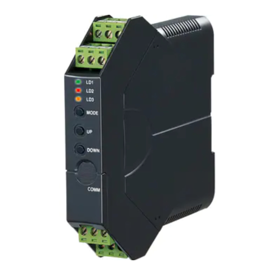
INSTRUCTION MANUAL
FREQUENCY TRANSMITTER
(field- and PC-configurable)
BEFORE USE ....
Thank you for choosing M-System. Before use, please check
contents of the package you received as outlined below.
If you have any problems or questions with the product,
please contact M-System's Sales Office or representatives.
■ PACKAGE INCLUDES:
Signal conditioner ......................................................... (1)
I/O range and tag name label sheet ............................ (1)
■ MODEL NO.
Confirm Model No. marking on the product to be exactly
what you ordered.
■ INSTRUCTION MANUAL
This manual describes necessary points of caution when
you use this product, including installation, connection and
basic maintenance procedures.
The M3LPA2 with Option /A is programmable using the PC
configurator software. For detailed information on the PC
configuration, refer to the M3LPACFG instruction manual.
The M3LPACFG PC Configurator Software is downloadable
at M-System's web site: http://www.m-system.co.jp.
POINTS OF CAUTION
■ CONFORMITY WITH UL
• This equipment is suitable for use in a Pollution Degree 2
environment.
• This equipment is to be used with the maximum operat-
ing voltage 30Vrms and 42.4Vpeak or 60V DC.
• The equipment must be mounted inside a suitable fire en-
closure.
• Operating temperature: -25 to +55°C (-13 to +131°F)
■ CONFORMITY WITH EC DIRECTIVES
• Functional insulation is maintained between the signal
input and output.
• Altitude up to 2000 meters
• The equipment must be mounted inside a panel.
• Insert noise filters for the power source connected to the
unit. Densei-Lambda Model MBS-1220-22 or equivalent
is recommended.
• The actual installation environments such as panel con-
figurations, connected devices, connected wires, may af-
fect the protection level of this unit when it is integrated
in a panel system. The user may have to review the CE
requirements in regard to the whole system and employ
additional protective measures to ensure the CE conform-
ity.
■ POWER INPUT RATING & OPERATIONAL RANGE
Locate the power input rating marked on the product and
confirm its operational range as indicated below:
100 – 240V AC rating: 85 – 264V, 47 – 66 Hz, approx. 3 – 5VA
10 – 32V DC rating: 9 – 36V, approx. 3W
■ SAFETY PRECAUTION
Before you remove the unit or mount it, turn off the power
supply and input signal for safety.
■ ENVIRONMENT
• Indoor use
• When heavy dust or metal particles are present in the air,
install the unit inside proper housing with sufficient ven-
tilation.
• Do not install the unit where it is subjected to continuous
vibration. Do not subject the unit to physical impact.
• Environmental temperature must be within -25 to +65°C
(-13 to +149°F) with relative humidity within 0 to 95% RH
in order to ensure adequate life span and operation.
• Be sure that the ventilation slits are not covered with ca-
bles, etc.
■ WIRING
• Do not install cables (power supply, input and output)
close to noise sources (relay drive cable, high frequency
line, etc.).
• Do not bind these cables together with those in which
noises are present. Do not install them in the same duct.
■ AND ....
The unit is designed to function as soon as power is sup-
plied, however, a warm up for 10 minutes is required for sat-
isfying complete performance described in the data sheet.
5-2-55, Minamitsumori, Nishinari-ku, Osaka 557-0063 JAPAN
Phone: +81(6)6659-8201 Fax: +81(6)6659-8510 E-mail: info@m-system.co.jp
M3LPA2
MODEL
EM-2657 Rev.3
M3LPA2
P. 1 / 10
Advertisement
Table of Contents

Related Manuals for M-system M3LPA2


Summary of Contents for M-system M3LPA2
- Page 1 • Do not install cables (power supply, input and output) basic maintenance procedures. close to noise sources (relay drive cable, high frequency The M3LPA2 with Option /A is programmable using the PC line, etc.). configurator software. For detailed information on the PC • Do not bind these cables together with those in which...
-
Page 2: Component Identification
EM-2657 Rev.3 P. 2 / 10 5-2-55, Minamitsumori, Nishinari-ku, Osaka 557-0063 JAPAN Phone: +81(6)6659-8201 Fax: +81(6)6659-8510 E-mail: info@m-system.co.jp... -
Page 3: Terminal Connections
AI 0.25-8YE 0.2 to 0.25 mm AI 0.34-8TQ 0.25 to 0.34 mm AI 0.5-8WH 0.34 to 0.5 mm AI 0.75-8GY 0.5 to 0.75 mm AI 1.0-8RD 0.75 to 1.0 mm AI 1.5-8BK 1.0 to 1.5 mm • Expose wire conductors by 8 mm (0.31”). Wire exposure Recommended ferruled wire 8 mm 8 mm EM-2657 Rev.3 P. 3 / 10 5-2-55, Minamitsumori, Nishinari-ku, Osaka 557-0063 JAPAN Phone: +81(6)6659-8201 Fax: +81(6)6659-8510 E-mail: info@m-system.co.jp... - Page 4 1 – 5V p-p 5V OFF OFF 0.5 – 1V p-p 1V OFF 0.1 – 0.5V p-p 0.5V OFF *1. Max. 30V rms, 42.4V peak or 60V DC for UL approval *2. Max. 30V rms, 42.4V peak or 50V DC for UL approval ■ CUTOUT (SW3) Table 6 SW3-7 is usable only with the M3LPA2-x/B. CUTOUT SW3-7 With (0.1% fixed) Without EM-2657 Rev.3 P. 4 / 10 5-2-55, Minamitsumori, Nishinari-ku, Osaka 557-0063 JAPAN Phone: +81(6)6659-8201 Fax: +81(6)6659-8510 E-mail: info@m-system.co.jp...
-
Page 5: Maintenance
■ OUTPUT TYPE / PC CONFIG (SW1) * Table 12 OUTPUT SW1-4 SW1-3 SW1-2 SW1-1 0 – 20mA -2.5 – +2.5V OFF OFF -10 – +10V OFF EM-2657 Rev.3 P. 5 / 10 5-2-55, Minamitsumori, Nishinari-ku, Osaka 557-0063 JAPAN Phone: +81(6)6659-8201 Fax: +81(6)6659-8510 E-mail: info@m-system.co.jp... - Page 6 ■ PREPARATION (e.g. M3LPA2-R4/A, DC powered type) 1) Mount the DIP-SW-configured M3LPA2 on to a DIN rail. 2) Connect the M3LPA2 to a simulator and a multimeter and to a DC power source as shown below. 3) Turn the power supply on and wait for 10 minutes. M3LPA2...
- Page 7 RUN MODE If the LED does not change, the entered level may be inappropriate: e.g. out of usable range. *For the model M3LPA2-x/A, the green LED is blinking. For the model M3LPA2-x/B, the green LED turns on. EM-2657 Rev.3 P. 7 / 10 5-2-55, Minamitsumori, Nishinari-ku, Osaka 557-0063 JAPAN Phone: +81(6)6659-8201 Fax: +81(6)6659-8510 E-mail: info@m-system.co.jp...
- Page 8 100% (UP). Note 3: Once the transmitter enters the fine zero or span calibration mode, the output goes to preadjusted 0% or 100% value respectively regardless of the present input signal. EM-2657 Rev.3 P. 8 / 10 5-2-55, Minamitsumori, Nishinari-ku, Osaka 557-0063 JAPAN Phone: +81(6)6659-8201 Fax: +81(6)6659-8510 E-mail: info@m-system.co.jp...
- Page 9 AMPLITUDE (mAp-p) RANGE (Vp-p) LEVEL (V) 1 6 (1.6Vp-p) 1 – 5 0.8 2 5 (2.5Vp-p) 1 – 5 HOW TO RESET TO DEFAULT STATUS 1) Set SW3-4 and SW3-5 to OFF position. 2) Turn on the power supply to the transmitter while pressing MODE button. 3) Wait until green light turns on at the LD1, LD2 and LD3. 4) Reset SW3-4 and SW3-5 to the previous position. Turn off and on the power supply. EM-2657 Rev.3 P. 9 / 10 5-2-55, Minamitsumori, Nishinari-ku, Osaka 557-0063 JAPAN Phone: +81(6)6659-8201 Fax: +81(6)6659-8510 E-mail: info@m-system.co.jp...
-
Page 10: Status Indicator Led
10 11 12 DIN RAIL 35mm wide 18 (.71) 110.5 (4.35) [5 (.20)] • When mounting, no extra space is needed between units. EM-2657 Rev.3 P. 10 / 10 5-2-55, Minamitsumori, Nishinari-ku, Osaka 557-0063 JAPAN Phone: +81(6)6659-8201 Fax: +81(6)6659-8510 E-mail: info@m-system.co.jp...
Need help?
Do you have a question about the M3LPA2 and is the answer not in the manual?
Questions and answers