Table of Contents
Advertisement
Quick Links
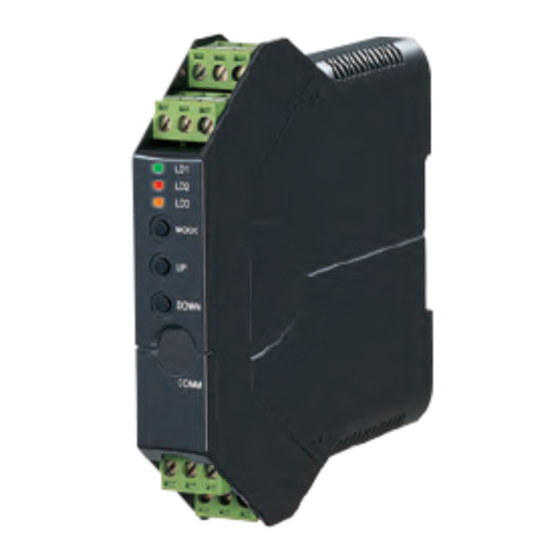
INSTRUCTION MANUAL
UNIVERSAL TRANSMITTER
(field- and PC-configurable)
BEFORE USE ....
Thank you for choosing M-System. Before use, please check
contents of the package you received as outlined below.
If you have any problems or questions with the product,
please contact M-System's Sales Office or representatives.
■ PACKAGE INCLUDES:
Signal conditioner ............................................................(1)
Terminal block with CJC sensor .....................................(1)
I/O range and tag name label sheet ...............................(1)
■ MODEL NO.
Confirm Model No. marking on the product to be exactly
what you ordered.
■ INSTRUCTION MANUAL
This manual describes necessary points of caution when
you use this product, including installation, connection and
basic maintenance procedures. For detailed information,
refer to the operating manual (EM-2653-B).
The M3LR with Option /A is programmable using the PC
configurator software. For detailed information on the PC
configuration, refer to the M3LRCFG instruction manual.
The M3LRCFG PC Configurator Software and operating
manual are downloadable at M-System's web site: http://
www.m-system.co.jp.
POINTS OF CAUTION
■ CONFORMITY WITH EU DIRECTIVES
• This equipment is suitable for Pollution Degree 2 and In-
stallation Category II. Reinforced insulation (signal in-
put or output to power input: 300V) and basic insulation
(signal input to output: 300V) are maintained. Prior to
Installation, check that the insulation class of this unit
satisfies the system requirements.
• Altitude up to 2000 meters
• The equipment must be mounted inside a panel.
• The actual installation environments such as panel con-
figurations, connected devices, connected wires, may af-
fect the protection level of this unit when it is integrated
in a panel system. The user may have to review the CE
requirements in regard to the whole system and employ
additional protective measures to ensure the CE conform-
ity.
■ POWER INPUT RATING & OPERATIONAL RANGE
Locate the power input rating marked on the product and
confirm its operational range as indicated below:
100 – 240V AC rating: 85 – 264V, 47 – 66 Hz, approx. 4 – 6VA
10 – 32V DC rating: 9 – 36V, approx. 3W
■ SAFETY PRECAUTION
Before you remove the unit or mount it, turn off the power
supply and input signal for safety.
■ ENVIRONMENT
• Indoor use
• When heavy dust or metal particles are present in the
air, install the unit inside proper housing with sufficient
ventilation.
• Do not install the unit where it is subjected to continuous
vibration. Do not subject the unit to physical impact.
• Environmental temperature must be within -25 to +60°C
(-13 to +140°F) with relative humidity within 30 to 95%
RH in order to ensure adequate life span and operation.
• Be sure that the ventilation slits are not covered with ca-
bles, etc.
■ WIRING
• Do not install cables (power supply, input and output)
close to noise sources (relay drive cable, high frequency
line, etc.).
• Do not bind these cables together with those in which
noises are present. Do not install them in the same duct.
■ AND ....
The unit is designed to function as soon as power is sup-
plied, however, a warm up for 10 minutes is required for sat-
isfying complete performance described in the data sheet.
5-2-55, Minamitsumori, Nishinari-ku, Osaka 557-0063 JAPAN
Phone: + 81 ( 6 ) 6659-8201 Fax: + 81 ( 6 ) 6659-8510 E-mail: info@m-system.co.jp
M3LU2
MODEL
EM-2653-A P. 1 / 8
M3LU2
Advertisement
Table of Contents

Related Manuals for M-system M3LU2


Summary of Contents for M-system M3LU2
-
Page 1: Before Use
10 minutes is required for sat- isfying complete performance described in the data sheet. EM-2653-A P. 1 / 8 5-2-55, Minamitsumori, Nishinari-ku, Osaka 557-0063 JAPAN Phone: + 81 ( 6 ) 6659-8201 Fax: + 81 ( 6 ) 6659-8510 E-mail: info@m-system.co.jp... - Page 2 EM-2653-A P. 2 / 8 5-2-55, Minamitsumori, Nishinari-ku, Osaka 557-0063 JAPAN Phone: + 81 ( 6 ) 6659-8201 Fax: + 81 ( 6 ) 6659-8510 E-mail: info@m-system.co.jp...
- Page 3 • Expose wire conductors by 8 mm (0.31”). Wire exposure Recommended ferruled wire 8 mm 8 mm EM-2653-A P. 3 / 8 5-2-55, Minamitsumori, Nishinari-ku, Osaka 557-0063 JAPAN Phone: + 81 ( 6 ) 6659-8201 Fax: + 81 ( 6 ) 6659-8510 E-mail: info@m-system.co.jp...
- Page 4 SW3-8 Configuration mode can be Con- DIP SW firmed with the front LED. EM-2653-A P. 4 / 8 5-2-55, Minamitsumori, Nishinari-ku, Osaka 557-0063 JAPAN Phone: + 81 ( 6 ) 6659-8201 Fax: + 81 ( 6 ) 6659-8510 E-mail: info@m-system.co.jp...
- Page 5 (same for all steps). EM-2653-A P. 5 / 8 5-2-55, Minamitsumori, Nishinari-ku, Osaka 557-0063 JAPAN Phone: + 81 ( 6 ) 6659-8201 Fax: + 81 ( 6 ) 6659-8510 E-mail: info@m-system.co.jp...
- Page 6 *For the model M3LU2-x/A, the green LED is blinking. For the model M3LU2-x/B, the green LED turns on. EM-2653-A P. 6 / 8 5-2-55, Minamitsumori, Nishinari-ku, Osaka 557-0063 JAPAN Phone: + 81 ( 6 ) 6659-8201 Fax: + 81 ( 6 ) 6659-8510 E-mail: info@m-system.co.jp...
- Page 7 Thermocouple input: [Accuracy + Cold Junction Compensation Error 1.0°C (1.80.9°F)] or ±0.1% of span, whichever is greater. For current output, overall accuracy degrades another 0.1% with spans ≤2mA. EM-2653-A P. 7 / 8 5-2-55, Minamitsumori, Nishinari-ku, Osaka 557-0063 JAPAN Phone: + 81 ( 6 ) 6659-8201 Fax: + 81 ( 6 ) 6659-8510 E-mail: info@m-system.co.jp...
- Page 8 *Used only with a thermocouple input • When mounting, no extra space is needed between units. EM-2653-A P. 8 / 8 5-2-55, Minamitsumori, Nishinari-ku, Osaka 557-0063 JAPAN Phone: + 81 ( 6 ) 6659-8201 Fax: + 81 ( 6 ) 6659-8510 E-mail: info@m-system.co.jp...
Need help?
Do you have a question about the M3LU2 and is the answer not in the manual?
Questions and answers