Table of Contents
Advertisement
Quick Links
Advertisement
Table of Contents

Related Manuals for ETAS FlexRay ES920.1


Summary of Contents for ETAS FlexRay ES920.1
- Page 1 ES920.1 FlexRay Module User’s Guide...
- Page 2 The data in this document may not be altered or amended without special noti- fication from ETAS GmbH. ETAS GmbH undertakes no further obligation in rela- tion to this document. The software described in it can only be used if the customer is in possession of a general license agreement or single license.
-
Page 3: Table Of Contents
ETAS Contents Contents 1 About this Manual ..........6 Identification of Safety Notices . - Page 4 ETAS Contents 4.4.2 Firmware Update........21 5 Getting Started .
- Page 5 9 ETAS Contact Addresses ........
-
Page 6: About This Manual
ETAS About this Manual About this Manual This chapter contains information about the following topics: • "Identification of Safety Notices" on page 6, • "Presentation of Information" on page 6, • "Scope of Supply" on page 7, • "Additional Information" on page 7. -
Page 7: Scope Of Supply
(see chapter 8.1 on page 39). Additional cables and adapters can be obtained separately from ETAS. A list of available accessories and their order designation is located in chapter "Accesso- ries" on page 39 of this manual or in the ETAS product catalog. -
Page 8: Basic Safety Notices
• "Requirements for Users and Duties for Operators" on page 8, • "Intended Use" on page 8. General Safety Information Please observe the Product Safety Notices ("ETAS Safety Notice") and the follow- ing safety notices to avoid health issues or damage to the device. Note Carefully read the documentation (Product Safety Advice and this User's Guide) that belongs to the product prior to the startup. - Page 9 ETAS Basic Safety Notices Requirements for the technical state of the product The product is designed in accordance with state-of-the-art technology and rec- ognized safety rules. The product may be operated only in a technically flawless condition and according to the intended purpose and with regard to safety and dangers as stated in the respective product documentation.
- Page 10 Connect the power cable only with a suitable vehicle battery or with a suitable lab power supply! The connection to power outlets is not allowed! To prevent an inadvertent insertion in power outlets, ETAS recom- mends to equip the power cables with safety banana plugs in areas with power outlets.
- Page 11 • Use exclusively ETAS cables at the connections of the module! • Adhere to the maximum permissible cable lengths! • Do not use any damaged cables! Cables may be repaired only by ETAS! • Never apply force to insert a plug into a socket. Ensure that there is no contamination in and on the connection, that the plug fits the socket, and that you correctly aligned the plugs with the connection.
- Page 12 Maintenance The product is maintenance-free. Repair If an ETAS hardware product should require a repair, return the product to ETAS. Cleaning the module housing • Use a dry or lightly moistened, soft, lint-free cloth for cleaning the module housing.
- Page 13 CAUTION! Damage to the module and loss of properties based on IP30! Do not open or change the module housing! Work on the module housing may only be performed by ETAS. Potential equalization CAUTION! Potential equalization in the vehicle is possible via the shield of...
-
Page 14: Hardware Description
ETAS Hardware Description Hardware Description This chapter provides an overview of FlexRay and the ES920.1 module and pro- vides you with information on its properties, connectors and the LED. Overview 3.1.1 FlexRay The complexity of vehicle electronics is permanently on the increase due to the increasing number, growing function scope and the networking of electronic ECUs in vehicles. -
Page 15: Definitions
ETAS Hardware Description 3.1.2 Definitions FlexRay FlexRay is a scalable and fault-tolerant communication system for deter- ministic data exchange at high transfer rates. Using the time multiplex procedure enables the creation of distributed systems with a highly mod- ular structure and high safety demands. The high bandwidth of 10 MBaud... -
Page 16: Features
ETAS Hardware Description ES920.1 3.2.1 Features The ES920.1 FlexRay Module, when accommodated in the extension slot of the ES910 Rapid Prototyping Module, enables rapid prototyping applications at Flex- Ray channels. Note The ES920.1 FlexRay Module can be operated in the extension slot of the ES910.2 and the ES910.3-A. - Page 17 – Not sensitive to extreme environmental conditions (temperature, EMC) – High mechanical stability and durability • Part of the ETAS Tool Suite – Rapid prototyping of control functions with MATLAB®/Simulink®, ASCET-MD as well as C by integrating into INTECRIO –...
-
Page 18: View Of The Module
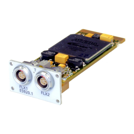
ETAS Hardware Description 3.2.2 View of the Module The following figure shows the ES920.1 FlexRay module with the position of the ports and the LED. Fig. 3-1 ES920.1 Module 3.2.3 Ports The FlexRay ports FLX1 for channel A and FLX2 for channel B are on the front of the ES920.1. -
Page 19: Functional Description
Each of the topologies requires the relevant bus termination. The FlexRay termi- nation designated by the ETAS FlexRay specification is 100 Ohm. To support the creation of a rapid prototyping environment in FlexRay networks, ETAS provides FlexRay cables with corresponding FlexRay terminations. -
Page 20: Wake Up" Function
ETAS Functional Description Power Connect Power Disconnect Wake-Up STANDBY Sleep Fig. 4-2 Operating Modes For more detailed information on the operating modes refer to the ES910 man- ual. Note The ON/AUTO switch of the ES910 must be switched to AUTO for this func- tion to be able to be used. -
Page 21: Sleep" Function
ETAS Functional Description Level Zeit 4 s 40 s DATA_0 4 s 40 s DATA_1 or Idle 4.3.2 “Sleep” Function The “Sleep” condition is fulfilled as soon as there is no further FlexRay traffic. 4.3.3 Configuration The “Wake Up” and “Sleep” behavior of the ES920.1 are configured in the web interface of the ES910 module (see section 5.5.2 on page 29). -
Page 22: Getting Started
ETAS Getting Started Getting Started The “Getting Started” chapter contains a description of how to install the ES920.1 in and remove it from the ES910 module, the applications, wiring, con- figuration and notes on troubleshooting for the ES920.1. Assembly The extension slot on the front of the ES910 has a removable front panel. You have to replace this front panel with the ES920.1 module if you want to use the... -
Page 23: Installing The Es920.1 In The Es910 Module
ETAS Getting Started • Unscrew and remove the four screws from the cor- ners of the front panel of the extension slot. • Keep the screws in a safe place. They are needed to secure the ES920.1 module. • Remove the front panel. - Page 24 ETAS Getting Started • Position the ES920.1 in front of the extension slot of the ES910 module. Align the back of the ES920.1 with the front of the housing of the ES910. Note The labeling on the fronts of both modules must be pointing in the same direction! •...
-
Page 25: Disassembly
ETAS Getting Started Disassembly 5.2.1 Removing the ES920.1 from the ES910 Module To remove the ES920.1 from the ES910, you need a flat-bladed screwdriver (width of edge 2 mm). To make removing the device simpler, make sure you have two CBF100-2 FlexRay cables readily available. -
Page 26: Attaching The Front Panel Of The Es910 Extension Slot
ETAS Getting Started • Remove the two cables from the ES920.1. • Store the ES920.1 in accordance with the ESD reg- ulations. 5.2.2 Attaching the Front Panel of the ES910 Extension Slot To attach the front panel of the ES910 extension slot: •... -
Page 27: Applications
ETAS Getting Started Applications 5.3.1 Function Development for FlexRay ECUs In conjunction with the ES920.1, the ES910 enables the creation of a highly effi- cient FlexRay node with two channels for sending and receiving FlexRay frames (see Fig. 5-1 on page 27). -
Page 28: Wiring
The ports of the ES920.1 must be wired in accordance with the FlexRay speci- fication. ETAS supplies special connecting cables which can be ordered separately if required. An overview is contained in the chapter "Accessories" on page 39. The CBF100-2 cable, a Y cable, is used to split the FlexRay bus. Termination resis- tors for this cable can be ordered separately. -
Page 29: Configuring The Es920.1
ETAS Getting Started Configuring the ES920.1 The ES920.1 is configured on your PC in the application program; the “Wake Up” function of the ES920.1 is configured in the web interface of the ES910 module. 5.5.1 Web Interface The web interface of the ES910 consists of a home page, a page for customized configuration of the ES920.1 for the “Wake Up”... -
Page 30: Troubleshooting
ETAS Getting Started Troubleshooting Please observe the LEDs which provide information on the functions of the ports and the ES920.1 (see the section "LEDs" on page 18) to be able to judge the operational state of the ES920.1 as well as troubleshooting measures. -
Page 31: Technical Data
ETAS Technical Data Technical Data This chapter describes general data, electrical data and the pin assignment of the ES920.1. General Data 6.1.1 Identifications on the Product The following symbols are used for identifying the product: Symbol Description The User's Guide must be read prior to the startup of the... -
Page 32: Rohs Conformity
The user is obligated to separate the waste equipment and to provide it to the WEEE return system for reuse. The WEEE Directive applies to all ETAS devices, but not to external cables or bat- teries. ES920.1 - User’s Guide... -
Page 33: Use Of Open Source Software
Technical Data Additional information about the recycling program of ETAS GmbH is available from the ETAS sales and service locations (see chapter 9 on page 40). Use of Open Source Software The product uses Open Source Software (OSS). This software is installed in the product at the time of delivery and does not have to be installed or updated by the user. -
Page 34: Es920.1 Firmware
ETAS Technical Data ES920.1 mounted in the ES910.3-A To configure the ES920.1 mounted in the ES910.3-A and for control and data acquisition, you need software in the following versions and higher: Support in Application Software Application Classifica- INCA INTECRIO ASCET-RP... -
Page 35: Electrical Data
ETAS Technical Data Electrical Data This section contains the electrical data on the ES920.1. 6.8.1 Power Supply Operating voltage Power supply via extension slot of the ES910 Input voltage 3.3 V; 5 V Power consumption (operation) 1.2 W (typ.), 1.8 W (max.) Current consumption (standby) <... -
Page 36: Pin Assignment
ETAS Technical Data Pin Assignment Note All ports are shown with a view of the ports of the ES920.1. All shields are at case potential. Fig. 6-2 FlexRay Ports (FLX1, FLX2) Signal Meaning FlexRay GND Ground (FlexRay) FlexRay Low FlexRay Low... -
Page 37: Cables And Accessories
ETAS Cables and Accessories Cables and Accessories Note Only use ETAS cables at the ports of the ES920.1. The maximum admissible cable lengths must be adhered to. FlexRay Interface Cable CBF100.2-2 F 00K 104 180 0000 FlexRay Side A Side B Side C Fig. -
Page 38: Flexray Interface Termination Resistor
ETAS Cables and Accessories FlexRay Interface Termination Resistor 100R0 / 1% Fig. 7-2 CBFX131-0 Termination Resistor Product Length Order Number CBFX131.1-0 F 00K 104 689 ES920.1 - User’s Guide... -
Page 39: Ordering Information
ETAS Ordering Information Ordering Information ES920.1 Order Name Short Name Order Number ES920.1 FlexRay Module (2-CH) ES920.1 F 00K 104 540 Package Contents ES920.1 FlexRay Module (2-CH), 2 x cable CBF100-2, 2 x FlexRay termination resistor CBFX131-0, ES900_Screws, List "Content of this Package",... -
Page 40: Etas Contact Addresses
Germany WWW: www.etas.com ETAS Subsidiaries and Technical Support For details of your local sales office as well as your local technical support team and product hotlines, take a look at the ETAS website: ETAS subsidiaries WWW: www.etas.com/en/contact.php ETAS technical support WWW: www.etas.com/en/hotlines.php... -
Page 41: Figures
ETAS Figures Figures Fig. 3-1 ES920.1 Module ..................18 Fig. 3-2 ES920.1Ports ....................18 Fig. 4-1 Block Diagram of the ES920.1 ..............19 Fig. 4-2 Operating Modes..................20 Fig. 4-3 Definition of the “Wake Up Pattern” ............20 Fig. 5-1 Function Development for FlexRay ECUs with INTECRIO and the ES910 Rapid Prototyping Module.................. - Page 42 Figures ETAS ES920.1 - User’s Guide...
-
Page 43: Index
“Wake Up” function 20 Electrical data 35 Accessories 39 Electrical safety 9 Accident prevention 8 ES920.1 Firmware 21 Ambient temperature 34 ETAS Contact Addresses 40 Applications 27 Attaching 26 Attaching the front panel 26 Features 16 Firmware 21 Firmware update 21... - Page 44 Index ETAS Software Hardware system requirements 33 system requirements 33 Standards 31 Hardware description 14 Standards and Norms 31 Supply voltage 35 System requirements 33 Identifying the product 31 Installing in the ES910 23 Technical data 31 Troubleshooting 30 Mechanical data 34...
Need help?
Do you have a question about the FlexRay ES920.1 and is the answer not in the manual?
Questions and answers