Table of Contents
Advertisement
Advertisement
Table of Contents

Related Manuals for ETAS ES584.1


Summary of Contents for ETAS ES584.1
- Page 1 ES584.1 CAN FD and LIN Bus Interface USB Module User’s Guide...
- Page 2 The data in this document may not be altered or amended without special noti- fication from ETAS GmbH. ETAS GmbH undertakes no further obligation in rela- tion to this document. The software described in it can only be used if the customer is in possession of a general license agreement or single license.
-
Page 3: Table Of Contents
Y-Cable ........... 19 ES584.1 – User’s Guide... - Page 4 Problems with the ES584.1 ........
- Page 5 9 ETAS Contact Addresses ........
- Page 6 ETAS Contents ES584.1 – User’s Guide...
-
Page 7: About This Manual
Indicates a possible danger with moderate risk of death or (serious) physical injury if not avoided. CAUTION! Indicates a hazard with low risk of minor or moderate physical injury or damage to property if not avoided. ES584.1 – User’s Guide... -
Page 8: Presentation Of Information
(see chapter 8.1 on page 49). Additional cables and adapters can be obtained separately from ETAS. A list of available accessories and their order designation can be found in chapter "Acces- sories"... -
Page 9: Basic Safety Notices
Read the documentation supplied with the product (Product Safety Advice and this user manual) prior to starting up the product. ETAS GmbH does not assume any liability for damage due to improper handling, improper use or non-compliance with safety measures. - Page 10 The module does not have an operating voltage switch. It can be de-energized as follows: • Unplug the cable from the module's signal inputs – Unplug the USB connector from the PC – Unplug the USB connector from the drive recorder module – De-energize the drive recorder module. ES584.1 – User’s Guide...
- Page 11 • Use exclusively ETAS cables at the module's connections. • Adhere to the maximum permissible cable lengths. • Do not use any damaged cables. Cables may be repaired only by ETAS. • Never apply force to insert a plug into a socket. Ensure that there is no contamination in and on the socket, that the plug fits the socket, and that you correctly aligned the plugs with the socket.
- Page 12 Damage to the module and loss of properties as per the pro- tection class. Do not open or change the module housing. Work on the module housing may only be performed by ETAS. Potential equalization CAUTION! Potential equalization in the vehicle is possible via the shield of ...
-
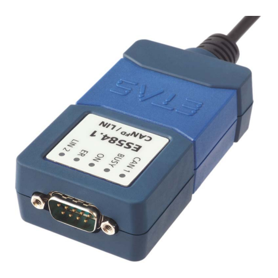
Page 13: Hardware Description
• "Updating the Firmware" on page 21. Overview The ES584.1 CAN FD and LIN Bus Interface USB Module is part of the range of compact ETAS bus interface modules. It is equipped with a CAN/CAN FD interface and with a LIN interface for connec- tion to vehicle buses or ECUs, as well as a USB port for connection to a PC or a drive recorder. -
Page 14: Application Areas
ES584.1 access to the CAN and LIN bus for measurement, calibration and diagnostics. The ES584.1 can be connected to a vehicle's CAN bus via the diagnostics service interface. When validating the vehicle diagnostics, the module can be used together with ODX-LINK, the INCA add-on for ECU diagnostics, as an interface for OBD-on- CAN, as well as to read and delete diagnostics error codes (DTCs). -
Page 15: Properties
ETAS Hardware Description Properties The most important properties of the ES584.1 CAN FD and LIN Bus Interface USB Module at a glance: • 1 CAN/CAN FD interface – CAN operating modes CAN high-speed CAN FD – CAN protocols CAN V2.0a (standard 11-bit identifier) CAN V2.0b (extended 29-bit identifier) -
Page 16: Function Groups
CAN FD nodes can easily be integrated into the existing CAN infrastructure. The ES584.1 CAN FD and LIN Bus Interface USB Module has a CAN interface CAN on its nine-pin DSUB socket. The CAN interface is an independent CAN channel with its own CAN controller. -
Page 17: Minimum Requirements For The Can Connection
It must be connected to the cable or the plug. Note ETAS offers cables and terminating resistors of 120 ohm to set up CAN net- works. Some CAN networks are already terminated (for example in a vehicle), so no additional termination is required. -
Page 18: Lin Interface
Voltage supply on the LIN bus (pin assignment on the CBCF100 cable) 12 V LIN systems In 12 V LIN systems, the LIN node of the ES584.1 module can either be supplied externally by the LIN bus or internally by the module with the LIN reference volt- age V 24 V LIN systems In 24 V LIN systems, the LIN node of the ES584.1 module can only be supplied... -
Page 19: Usb Port
Power Supply The ES584.1 module is powered via the USB 2.0 port of a PC or a drive recorder. The module does not require an external power supply. Information on the requirements for the PC's USB port can be found in chapter 6.7.1 on page 37. -
Page 20: Operating State Display
Operating State Display Fig. 3-4 ES584.1 LEDs The ES584.1 is equipped with five LEDs for displaying the module's operating state, as well as for displaying the function of the two CAN and LIN interfaces (see Fig. 3-4 on page 20):... -
Page 21: Multi-Client Support
3.12 Updating the Firmware The firmware of the ES584.1 can be updated by the user so that future versions of the module can also be used. The firmware update is performed using the ETAS service software "Hardware Service Pack" (HSP) from the connected PC. - Page 22 ETAS Hardware Description ES584.1 – User’s Guide...
-
Page 23: Commissioning
• "Establishing the USB Connection" on page 28 ES584.1 USB Driver Note A specific USB driver must be installed on the PC for operating the ES584.1 module. The ES584.1 can be installed on plug & play-compatible operating systems (Win- dows 7, Windows 8 and Windows 10). Following installation of the driver, you can use/remove the ES584.1 module at any time. -
Page 24: Installation Procedure
ES584.1 to the USB port on your computer. Commissioning of the ES584.1 must be performed in the following sequence: 1. Installation of the USB drivers (ES584.1 not connected to the PC), 2. Establishing the USB connection, 3. Establishing the CAN connection. - Page 25 ETAS Commissioning • Read and accept the end user license agreement. • Click on Next. The installation of the USB driver starts. • Wait until the USB driver is installed. ES584.1 – User’s Guide...
- Page 26 ETAS Commissioning • Click on Exit. The installation of the USB driver for the ES584.1 is then complete. ES584.1 – User’s Guide...
-
Page 27: Verifying The Installation Of The Usb Driver
Fig. 4-1 Windows Device Manager If the ES584.1 USB driver was not correctly installed/uninstalled and Windows detects the module as connected, a symbol with an exclamation mark is shown next to the device. Run the driver installation program again to resolve this issue. -
Page 28: Establishing The Usb Connection
Commissioning Establishing the USB Connection After successful driver installation, the ES584.1 can be connected to the PC. Win- dows should detect the device and install the accompanying driver. Windows displays an information note in the start bar. In Fig. 4-2 on page 28, you can see an image of the information notes that appear. -
Page 29: Uninstalling The Usb Driver
ETAS Commissioning Uninstalling the USB Driver The USB driver for the ES584.1 can be uninstalled in the Windows Control Panel. Uninstalling the USB driver for the ES584.1: • Disconnect the ES584.1 module from the USB port on the PC or drive recorder. -
Page 30: J2534 Driver
The uninstallation of the USB driver for the ES584.1 is then complete. J2534 Driver Note Installation of a J2534 driver is not necessary for the ES584.1. The packages required to support the J2534 interface are automatically installed by the INCA application software. ES584.1 – User’s Guide... -
Page 31: Troubleshooting Problems
Troubleshooting Problems Troubleshooting Problems This chapter provides information on what you can do when problems arise with the ES584.1 and when general problems arise that are not specific to an individ- ual software or hardware product. Displays of the LEDs When assessing the operating state and rectifying faults on the ES584.1, note... - Page 32 ETAS Troubleshooting Problems Problem Diagnostics questions Possible solution The ES584.1 module is Did you install the Check whether the INCA not detected when exe- required version of INCA? version installed on your cuting the "Scan for PC meets the require- hardware"...
-
Page 33: Technical Data
Current consumption, max. ES584.1 Product designation Manufacturer's address Marking for China RoHS, see chapter 6.2.2 on page 35 Marking for RoHS, see chapter 6.2.1 on page 35 Marking for CE conformity, see chapter 6.3 on page 35 ES584.1 – User’s Guide... -
Page 34: Standards
6.1.4 Maintenance of the Product Do not open or modify the module housing. Work on the module may only be performed by qualified personnel. Return defective modules to ETAS for repair. 6.1.5 Cleaning the Product We recommend cleaning the product with a dry cloth. -
Page 35: Rohs Conformity
The user is obligated to separately collect old devices and hand them over to the WEEE return system for recycling. The WEEE Directive applies to all ETAS devices, but not to external cables or bat- teries. Additional information about the recycling program of ETAS GmbH is available from the ETAS sales and service locations (see chapter 9 on page 51). -
Page 36: Mechanical Data
Length of the integrated USB cable 1.5 m / 4.9 ft Weight Approx. 150 g / 5.291 oz. (with USB cable) Housing Nylon, rubberized Connection on PC side USB connector, type A Connection on bus side Nine-pin DSUB connector (DIN 41652) ES584.1 – User’s Guide... -
Page 37: System Requirements
The module does not support USB 1.0 interfaces. Prerequisite for successful initialization of the module Note A specific USB driver must be installed on the PC for operating the ES584.1 (see chapter 4.3 on page 24). Windows user rights Ensure that you have the necessary Windowsuser rights for installation of the USB driver (administrator rights). - Page 38 This document does not provide detailed descriptions of how the power man- ager can be deactivated. ES720.1 and ES820.1 drive recorders The ES584.1 module can be operated on the USB port of ES720.1 and ES820.1 drive recorders. ES584.1 – User’s Guide...
-
Page 39: Software
ETAS Technical Data 6.7.2 Software Supported applications and software requirements For operation of the ES584.1 and for data capture, you require software in the following versions or higher: INCA Application/pro- Classifi- INCA tocol cation add-on CAN monitoring V11.6.0 V7.2.6 CAN output V11.6.0... -
Page 40: Electrical Data
Max. 1 MBaud for 20 m bus length CAN FD (data): Max. 5 Mbit/s (operat- ing temperature range) CAN FD (data): Max. 8 Mbit/s (room temperature) CAN interface clients Max. 2 Controller ARM Cortex MCU Transceiver (physical layer) TJA1044G ES584.1 – User’s Guide... -
Page 41: Lin Interface
Compatible with the LIN standard used by Client 1 Electrical isolation Interface separated from the other interfaces : Selection of internal LIN V by INCA currently in preparation : Support for master operating mode by INCA currently in preparation ES584.1 – User’s Guide... -
Page 42: Terminal Assignment
Terminal Assignment Note All connections are shown with view of the module interfaces. The CAN bus is connected to the ES584.1 CAN FD and LIN Bus Interface USB Module via the nine-pin DSUB connector (see Fig. 6-3). Fig. 6-3 ES584.1 DSUB connector... -
Page 43: Cables And Accessories
Assigning DSUB connectors "1" and "2" of the CBCF100 cable to the ES584.1 If a CBCF100 cable is used at the CAN/LIN interface of the ES584.1 module, the interfaces are assigned to DSUB connectors "1" and "2" of the cable as follows: ES584.1... - Page 44 ETAS Cables and Accessories Pin assignment of the CBCF100 cable at the CAN/LIN interface of the ES584.1 The signals of the CAN/LIN interface of the ES584.1 module are assigned to DSUB connectors "1" and "2" of the CBCF100 cable as follows: DSUB socket ...
-
Page 45: Cbac180 Cable
ETAS Cables and Accessories CBAC180 Cable Fig. 7-4 CBAC180-2 cable OBDII (J1962) adapter cable for the CAN interface of the ES584.1 DSUB connec- OBD2 connec- Signal Note tion tion CAN High CAN High and CAN Low in a shielded twisted pair... -
Page 46: Cbh500 Cable
CBCX130.1-2 F 00K 103 784 Fig. 7-6 CBCX130 cable Note The CBH500 cable only supports one CAN channel. Order designation Short name Order number CAN interface cable, DSUB – DSUB (9fc- CBCX130-2 F-00K-103-784 9mc), 2 m ES584.1 – User’s Guide... -
Page 47: Cbcx131.1-0 Adapter
ETAS Cables and Accessories CBCX131.1-0 Adapter 120 Ohm Fig. 7-7 CBCX131.1-0 terminating resistor CAN 120 ohm terminating resistor, 2xDSUB (9fc+9mc) Order designation Short name Order number CAN 120 ohm terminating resistor, CBCX131-0 F-00K-103-786 2xDSUB (9fc+9mc) ES584.1 – User’s Guide... - Page 48 ETAS Cables and Accessories ES584.1 – User’s Guide...
-
Page 49: Order Information
ETAS Order Information Order Information ES584.1 CAN FD and LIN Bus Interface USB Module Order name Short name Order number ES584.1 CAN FD and LIN Bus Interface ES584.1 F-00K-110-831 USB Module Scope of supply ES584.1 CAN FD and LIN Bus Interface USB Module, ... - Page 50 ETAS Order Information ES584.1 – User’s Guide...
-
Page 51: Etas Contact Addresses
Germany WWW: www.etas.com ETAS Subsidiaries and Technical Support For details of your local sales office as well as your local technical support team and product hotlines, take a look at the ETAS website: ETAS subsidiaries WWW: www.etas.com/en/contact.php ETAS technical support WWW: www.etas.com/en/hotlines.php... - Page 52 ETAS ETAS Contact Addresses ES584.1 – User’s Guide...
-
Page 53: Figures
ETAS Figures Figures Fig. 3-1 ES584.1...................... 13 Fig. 3-2 ES584.1 block diagram ................16 Fig. 3-3 Voltage supply on the LIN bus (pin assignment on the CBCF100 cable) ..18 Fig. 3-4 ES584.1 LEDs....................20 Fig. 4-1 Windows Device Manager ................27 Fig. - Page 54 Figures ETAS ES584.1 – User’s Guide...
-
Page 55: Index
Labeling on the product 33 CBCX131.1-0 Adapter 47 CD-ROM 23 Cleaning 34 Maintenance 34 Commissioning 23 Multi-Client Support 21 Documentation 9 ODX-LINK 14 Operating Mode High-speed CAN 16 Electrical safety 10 Operating mode ES584.1 J2534 Driver 30 CAN FD 16 ES584.1 – User’s Guide... - Page 56 Open Source 35 System requirements 39 Standards 34 System Requirements 37 Time Stamp 16 USB connection 28 USB Port 19 Use, intended 9 User rights 37 Voltage Supply 40 Waste electrical and electronic equip- ment 35 WEEE 35 ES584.1 – User’s Guide...
Need help?
Do you have a question about the ES584.1 and is the answer not in the manual?
Questions and answers