
Related Manuals for ETAS ES313.1


Summary of Contents for ETAS ES313.1
- Page 1 ES313.1 A/D Module with Sensor Supply (4 CH) ES314.1 A/D Module with Sensor Supply (8 CH) User’s Guide...
- Page 2 The data in this document may not be altered or amended without special noti- fication from ETAS GmbH. ETAS GmbH undertakes no further obligation in rela- tion to this document. The software described in it can only be used if the customer is in possession of a general license agreement or single license.
-
Page 3: Table Of Contents
ETAS Contents Contents About this Manual ..........6 Identification of Safety Notices . - Page 4 Contents ETAS 5.1.3 Sensor Supply ........20 Data Transmission .
- Page 5 11 ETAS Contact Addresses ........
-
Page 6: About This Manual
About this Manual ETAS About this Manual This chapter contains information about the following topics: • "Identification of Safety Notices" on page 6 • "Presentation of Information" on page 7 • "Scope of Supply" on page 7 • "Additional Information" on page 7. -
Page 7: Presentation Of Information
(see chapter 10 on page 52). Additional cables and adapters can be obtained separately from ETAS. A list of available accessories and their order designation is located in chapter 10 on page 52 of this manual or in the ETAS product catalog. -
Page 8: Basic Safety Notices
• "Requirements for Users and Duties for Operators" on page 8 • "Intended Use" on page 8. General Safety Information Please observe the Product Safety Notices ("ETAS Safety Notice") and the follow- ing safety notices to avoid health issues or damage to the device. Note Carefully read the documentation (Product Safety Advice and this User's Guide) that belongs to the product prior to the startup. - Page 9 ETAS Basic Safety Notices Requirements for operation • Use the product only according with the specifications in the relevant User's Guide. Any other usage could jeopardize product safety. • Observe the requirements on the ambient conditions. • Do not use the product in potentially explosive areas.
- Page 10 Connecting to a mains socket is not allowed! To prevent the connector from accidentally being plugged into a mains socket, ETAS recommends using power supply cables with safety banana plugs in areas with mains sockets.. De-energizing the module The module does not have a power switch.
- Page 11 • Use exclusively ETAS cables at the connections of the module! • Adhere to the maximum permissible cable lengths! • Do not use any damaged cables! Cables may be repaired only by ETAS! CAUTION! Never apply force to insert a plug into a socket.
- Page 12 Maintenance The product is maintenance-free. Repair If an ETAS hardware product should require a repair, return the product to ETAS. Cleaning the module housing • Use a dry or lightly moistened, soft, lint-free cloth for cleaning the module housing.
-
Page 13: Es300 Product Family
This causes long setup times and high costs. With the ES300 modules, ETAS offers a decentral solution that significantly sim- plifies the measuring set-up of the sensors. The basic idea of this concept is to install the modules of the ES300 series spa- tially as close as possible to the sensors, to chain the modules with each other and to connect only the first module of this chain with the laptop in the vehicle. -
Page 14: Additional Properties
• All channels fully electrically isolated • Dovetailing for tool-free module connection of the ES300 modules • Different channel sampling rates • Part of the ETAS Tool Suite The complete technical data is located in chapter 8 on page 40. ES31x.1 User’s Guide... -
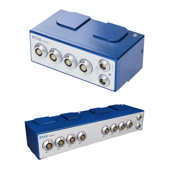
Page 15: Hardware Description
Fig. 4-1 Housing ES313.1 (above) and ES314.1 (below) The A/D modules with sensor supply ES313.1 and ES314.1 are part of the series of ES300 modules. The ES31x can record analog voltages, currents and sensor signals at 4 respectively 8 input channels. A sensor supply is available for each channel. -
Page 16: Properties
• Sample rate from 1 Hz to 2,000 kHz (measuring and calibrating) • Adjustable short circuit-proof sensor supply voltage (2.5 V to 15 V) The complete technical data of the ES313.1 and ES314.1 is located in chapter 8 on page 40. -
Page 17: Connections
Hardware Description Connections 4.4.1 Overview All plug connections of the ES300 modules are located on the front (see Fig. 4-2). Fig. 4-2 Connections ES313.1 (above) and ES314.1 (below) No. in Fig. 4-2 Connection Meaning LEMO Measurement input LEMO CAN bus and power supply The LEMO plug connectors used are installed in accordance with degree of pro- tection IP67. -
Page 18: Leds
Hardware Description ETAS LEDs The ES313.1 features a status LED for the display of the operating state. LED code Display State No power supply Illuminated green Operational Measurement in progress - Flashing green operation in a system with (0.9 s on / 0.1 s off) -
Page 19: Functional Description
ETAS Functional Description Functional Description This chapter contains information about the following topics: • "Sensor Connections" on page 19 • "Data Transmission" on page 20 • "Power supply" on page 22 • "Configuration" on page 23 • "Tool Integration" on page 23 •... -
Page 20: Sensor Supply
Functional Description ETAS 5.1.3 Sensor Supply Every sensor of ES31x that can be activated has its own separate, individually adjustable sensor supply voltage. The sensor supply voltage can be changed. The user can switch off the sensor supply voltage of every sensor connection in the application program or select one of the default values between +2.5 V and +15 V. -
Page 21: Properties
ETAS Functional Description Signal Bits Meaning Error Identification Code Acknowledge EOFS End of Frame For each CAN message, a maximum of 4 measured values can be transmitted in word format or a maximum of 8 measured values in byte format. -
Page 22: Transmission Speed
Functional Description ETAS 5.2.3 Transmission Speed The CAN bus of the ES3xx modules supports a fixed baud rate of 500 kBd. In the practical application, the transmission rate is limited by the following factors: • Length of bus line • Length of branch cables to the CAN stations •... -
Page 23: Configuration
The required minimum voltage for the supply of the system must be determined separately for every experimental set-up. For module chains that are fitted exclusively with ES31x modules, ETAS recom- mends the use of Y boost cables if the length of the module chain is greater than 40 modules. -
Page 24: Calibration
Information about the last calibration is stored at the device. Information about the process of the calibration service is available from your closest ETAS subsidiary. The contact information is located in chapter 11 on page 55. The ordering information for the calibration service is located in chapter 10 on page 52. -
Page 25: Commissioning
ETAS Commissioning Commissioning This chapter contains information about the following topics: • "General Installation Recommendations" on page 25 • "Assembly" on page 26 • "Applications" on page 28 • "Cabling" on page 28 General Installation Recommendations 6.1.1 Assembly Environment and Components for Fastening CAUTION! Damage or destruction of module is possible. -
Page 26: Assembly
Threaded bores Fig. 6-1 Bores and cable knockouts for cable ties using the example of ES313.1 Dovetailing The modules of the ES300 series can be fastened to each other without any additional accessories using the dovetailing at the upper and lower side of the modules. -
Page 27: Fig. 6-2 Mounting Bracket Using The Example Of Es313.1
Knockouts for cable ties Both sides of the ES313.1 feature 1 knockout each to the rear side of the module for fastening to other components using cable ties. ES31x.1 User’s Guide... -
Page 28: Applications
Sensor Supply Sensor Supply Fig. 6-3 ES300 modules and additional ETAS modules for MC applications The daisy-chain concept enables a simple network architecture since only the ES31x or the first module of the module chain must be connected with the bus interface module. -
Page 29: Daisy-Chain Connections
ETAS Commissioning 6.4.2 Daisy-Chain Connections The cabling is carried out from the first module in the direction of the end of the module chain. Cabling the first module with the subsequent module 1. Connect a CAN connecting cable with one of the two connectors of the first module. -
Page 30: Software Description
Software Description ETAS Software Description This chapter contains information about the following topics: • „Description“ on page 30 • „System Requirements“ on page 30 • „IPEaddon in INCA“ on page 30 • „Functions“ on page 31 Description The modules in the ES300 range can be configured using the IPEAddon for INCA. -
Page 31: Functions
Select one of the ES300 modules. 2. Click on Configure in the lower right-hand section of the screen. Fig. 7-1 Opening IPEaddon The IPETRONIK/ETAS window appears. Note When the IPEaddon is open, other INCA windows cannot be used. Functions 7.4.1... -
Page 32: Initialization
5.2.4 on page 22). Configuring the synchronization mode 1. Select Hardware Options in the menu bar. The IPETRONIK / ETAS: Options window appears. 2. Select the CAN interfaces tab. 3. In the CAN device synchronization mode section select one of the two Free-running or synchro- nous modes. - Page 33 ETAS Software Description Initializing modules The configuration of the modules is overwritten by the current configuration on the PC. Initializing modules 1. Select Hardware Initialize in the menu bar. The hardware initialization process starts. Once the initialization process is complete, the respective status of the modules is displayed with a symbol.
-
Page 34: Setting Up Aliasing Filters
You can find more information about the filters in chapter 5.1.1 on page 19 Setting up aliasing filters 1. Select Hardware Options in the menu bar. The IPETRONIK / ETAS: Options window appears. 2. Select the Options tab. 3. Activate/deactivate the option Aliasing-free filter settings. -
Page 35: Fig. 7-4 Module Configuration Context Menu
ETAS Software Description The following columns are also recommended: Column Description Bus load Utilization of the CAN bus CAN send rate Send speed of the CAN bus Date of last calibration Date on which the module was last calibrated Device production date... -
Page 36: Configuring A Channel
Software Description ETAS 7.4.5 Configuring a Channel Adding columns 1. Right-click on the header. A context menu appears. Fig. 7-6 Channel configuration context menu 2. Select the Column Chooser entry. The Customization window appears with the selection of all available columns. -
Page 37: Adjustment
ETAS Software Description Changing a value in a cell 1. Click in the cell containing the value you want to change. You can change the value manually or select a value from a drop-down list depending on the cell type. -
Page 38: Import / Export Module Configuration
Software Description ETAS 8. Click on Start. The Adjust channels temporary window appears. In the Result column, you can see whether the adjustment has been successful. Fig. 7-8 Offset adjustment 7.4.7 Import / Export Module Configuration Import You can import the configurations from a CSV file. - Page 39 ETAS Software Description Export You can export the configuration in the following file formats: • CANdb export • XML CANdb export • CSV export Exporting a configuration 1. Select Configure Export CANdb export in the menu bar XML CANdb export CSV export.
-
Page 40: Technical Data
Order number of the product (see chapter 10 on page 52) 10-33 V Operating voltage 1.5 A ES313.1 Current consumption ES314.1 Current consumption Risk of burning on hot surfaces of the module! Do not touch the surfaces of the module during operation at high ambient temperatures. -
Page 41: Standards
ETAS Technical Data 8.1.2 Standards The ES31x meets the following norms and standards: Standard Test EN 61326-1:2013 Electrical equipment for measurement, control and laboratory use - EMC requirements IEC 61010-1:2010 Safety requirements for electrical equipment IEC 61010-2-030:2010 Safety requirements for electrical... -
Page 42: Cleaning The Product
Products Regulation) applicable in the People's Republic of China. CE Marking With the CE mark attached to the product or its packaging, ETAS confirms that the product corresponds to the product-specific, applicable European Directives. The CE Declaration of Conformity for the product is available upon request. -
Page 43: Materials Subject To Declaration
The user is obligated to separately collect old devices and provide them to the WEEE return system for recycling. The WEEE Directive applies to all ETAS devices, but not to external cables or bat- teries. Additional information about the recycling program of ETAS GmbH is available from the ETAS sales and service locations (see chapter 11 on page 55). -
Page 44: Electrical Data
Technical Data ETAS Electrical Data 8.7.1 Voltage Supply Operating voltage 10 V to 33 V DC Power consumption ES313.1 max. 1.5 A ES314.1 max. 2 A 8.7.2 Host Interface Connection LEMO CAN 2.0B Data transmission (baud rate) 500 kBd Measuring data in the CAN message... -
Page 45: Sensor Inputs
ETAS Technical Data 8.7.4 Sensor Inputs Properties Input Channel ES313.1: 4 ES314.1: 8 A/D converter 16 bit SAR converter Hardware input filter Butterworth 8th order, 250 Hz cutoff frequency, switchable Sampling rate application tool 1 Hz to 2 kHz per channel, configurable Input voltage ranges 0.1 V to 60 V... -
Page 46: Signal Processing
Technical Data ETAS 8.7.5 Signal Processing Properties Resolution 16 bit Sample rate 1 Hz to 2 kHz per channel, configurable Hardware input filter Filter type Butterworth 8th order, 250 Hz cutoff frequency, switchable Software filter (DSP) Optional Cutoff frequency and filter type select-... -
Page 47: Lemo Sensor
ETAS Technical Data 8.8.2 LEMO Sensor Fig. 8-3 Terminal assignment Signal Description VIN + Voltage measurement input, plus Voltage measurement input, VIN - / IIN - ground / Current measurement input, minus IIN + Current measurement input, plus VOUT +... -
Page 48: Cables And Accessories
• "CAN Chain Connection Cable" on page 51 • "CAN Termination Resistor Plug" on page 51 • "Mounting Bracket" on page 51 Note Only use ETAS cables at the interfaces of the module. Adhere to the maximum cable lengths! Measurement Cables Fig. 9-1 Cable CBAV350.1... -
Page 49: Combined Can Connection And Power Supply Cable
ETAS Cables and Accessories Combined CAN Connection and Power Supply Cable 9.2.1 CBCP300.1 Fig. 9-2 Cable CBCP300.1 CAN connection and power supply cable for ES3xx modules with integrated ter- mination and power supply Product Length Order Number CBCP300.1-3 F-00K-110-544 9.2.2 CBCP3005.1... -
Page 50: Cbcp301.1
Cables and Accessories ETAS 9.2.3 CBCP301.1 Fig. 9-4 Cable CBCP301.1 CAN connection and power supply cable for ES3xx modules with integrated ter- mination and power supply Product Length Order Number CBCP301.1-3 F-00K-110-545 9.2.4 CBCP3015.1 Fig. 9-5 Cable CBCP3015.1 CAN connection and power supply cable for ES3xx modules with integrated ter-... -
Page 51: Can Chain Connection Cable
ETAS Cables and Accessories CAN Chain Connection Cable Fig. 9-6 Cable CBCX300.1 CAN chain connection cable for ES3xx modules Product Length Order Number CBCX300.1-0m15 0,15 m F-00K-110-546 CBCX300.1-0m5 0,5 m F-00K-110-547 CAN Termination Resistor Plug Fig. 9-7 CAN Termination Resistor Plug... -
Page 52: Ordering Information
ES313.1 A/D Module with Sensor Supply ES313.1 F-00K-110-531 (4 CH) Package Contents - ES313.1 A/D Module with Sensor Supply (4 CH) - CDROM ES3xx_CD (software for ES3xx and documentation) - List “Content of this Package” - ES3xx_Safety Advice - China-RoHS-leaflet_ES3xx_orange_cn... -
Page 53: Accessories
CBAV350.1-3 F-00K-110-542 (6mc) - open wires (6c), 3m Combined CAN Connection and Power Supply Cable Note If you require customized cables, please contact your ETAS contact partner. Order Name Short Name Order Number CAN Connection and Power Supply Cable CBCP300.1-3... -
Page 54: Can Termination Resistor Plug
Ordering Information ETAS 10.3.2 Can Termination Resistor Plug Order Name Short Name Order Number CAN termination resistor plug for ES3xx ES3xx_CAN_TERM F-00K-110-548 10.3.3 Mounting Bracket Order Name Short Name Order Number Mounting bracket for ES3xx modules ES3xx_BRACKET F-00K-110-549 (ES31x, ES341) 10.3.4... -
Page 55: Etas Contact Addresses
Germany WWW: www.etas.com ETAS Subsidiaries and Technical Support For details of your local sales office as well as your local technical support team and product hotlines, take a look at the ETAS website: ETAS subsidiaries WWW: www.etas.com/en/contact.php ETAS technical support WWW: www.etas.com/en/hotlines.php... -
Page 56: Figures
Fig. 5-1 Structure of a message according to CAN 2.0 B.......... 20 Fig. 6-1 Bores and cable knockouts for cable ties using the example of ES313.1 ..26 Fig. 6-2 Mounting bracket using the example of ES313.1 ........27 Fig. 6-3 ES300 modules and additional ETAS modules for MC applications.... -
Page 57: Index
Bores with thread for mounting bra- cket 26 Electrical data 44 Electrical isolation 19 Electrical safety 9 Cable ties 26 ETAS Contact Addresses 55 Cabling 28 Export module configuration 38 Daisy chain 29 Sensors 28 Cabling concept 13 Filter 19... - Page 58 Index ETAS Initialization 32 Scope of supply 7 Input filter 45 Sensor power supply 44 Input impedance 45 Sensor supply 20 Input voltage ranges 45 Signal processing 19 Input voltage resolution 45 Software description 30 Input voltage, maximum 45 Standards 41...
Need help?
Do you have a question about the ES313.1 and is the answer not in the manual?
Questions and answers