Table of Contents
Advertisement
Advertisement
Chapters
Table of Contents

Related Manuals for ETAS ES592.1


Summary of Contents for ETAS ES592.1
- Page 1 ETAS ES592.1 Prototyping and Interface Module User Guide...
- Page 2 The data in this document may not be altered or amended without special noti- fication from ETAS GmbH. ETAS GmbH undertakes no further obligation in relation to this document. The software described in it can only be used if the customer is in possession of a general license agreement or single license.
-
Page 3: Table Of Contents
Bus Terminating Resistor ........24 ES592.1 - User Guide... - Page 4 Troubleshooting ES592.1 Problems ........
- Page 5 ES592.1 ..............64 10.1.1 ES592.1 with CBP120 Power Supply Cable ..... . . 64 10.1.2 ES592.1 with CBP1205 Power Supply Cable .
-
Page 6: About This Document
Presentation of Instructions The target to be achieved is defined in the heading. The necessary steps for his are in a step-by-step guide: Target definition 1. Step 1 2. Step 2 3. Step 3 > Result ES592.1 - User Guide... -
Page 7: Typographical Conventions
ETAS About this Document Typographical Conventions Hardware Bold Menu commands, buttons, labels of the product Italic Emphasis on content and newly introduced terms Presentation of Supporting Information NOTE Contains additional supporting information. ES592.1 - User Guide... -
Page 8: About This Manual
Additional cables and adapters can be obtained separately from ETAS. A list of available accessories and their order designation is located in chapter “Cable and Accessoires” on page 65 of this manual or in the ETAS product catalog. Additional Information The configuration instructions for the module under INCA can be found in the corresponding software documentation. -
Page 9: Basic Safety Notices
• “Intended Use” on page 9 General Safety Information Please observe the Product Safety Notices ("ETAS Safety Notice") and the fol- lowing safety notices to avoid health issues or damage to the device. NOTE Carefully read the documentation (Product Safety Advice and this User's Guide) that belongs to the product prior to the startup. - Page 10 • Route the power cord in such a way that it is protected against abrasion, damages, deformation and kinking. Do not place any objects on the power cord! ES592.1 - User Guide...
- Page 11 • Adhere to the maximum permissible cable lengths! • Do not use any damaged cables! Cables may be repaired only by ETAS! • Never apply force to insert a plug into a socket. Ensure that there is no contamination in and on the connection, that the plug fits the socket, and that you correctly aligned the plugs with the connection.
- Page 12 Do not transport the modules at the cable of the module or any other cables. Maintenance The product is maintenance-free. Repair If an ETAS hardware product should require a repair, return the product to ETAS. Cleaning the module housing • Use a dry or lightly moistened, soft, lint-free cloth for cleaning the module housing.
- Page 13 ETAS Basic Safety Notices Cabling For detailed information about cabling, see the User's Guide of the module. ES592.1 - User Guide...
-
Page 14: Hardware Description
ETAS Hardware Description Hardware Description This chapter provides you with an overview of the ES592.1 with information on the housing, serial number, ports and LEDs. Overview The ES59x line is a range of powerful ECU and bus interface modules. The ES59x modules have an upstream Ethernet interface that guarantees data exchange with the host PC or with a Drive Recorder. -
Page 15: Delivery Variants
The housings of this device family can also quickly and easily be con- nected to one another (see the chapter 6.1 on page 27). The ES592.1 is intended for use in the lab, on the test bench and in the passen- ger cell of vehicles. -
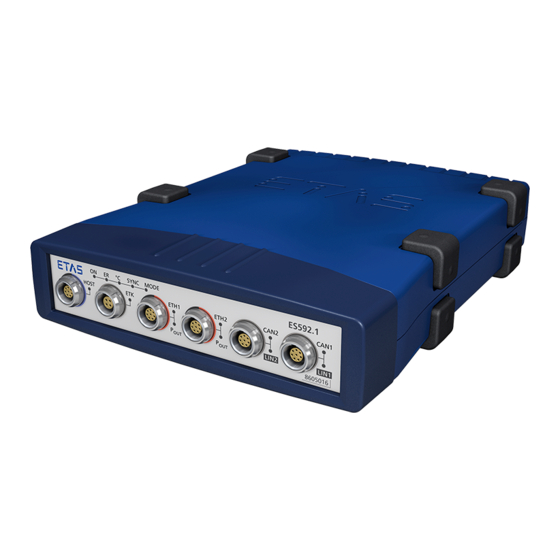
Page 16: Interfaces
CAN1 LIN2 LIN1 Fig. 4-2 Front Panel 4.5.2 Back Panel The interface 7-29V (power supply) is on the back panel of the ES592.1. 7‐29V Fig. 4-3 Back Panel LEDs 4.6.1 Flash Codes The ES592.1 is equipped with LEDs, which indicate the operational state of the module, as well as with LEDs which display the function of individual interfaces. -
Page 17: Operational State Of The Module
Flash Codes 4.6.2 Operational State of the Module Four LEDs can be found top left on the front panel of the ES592.1(see Fig. 4-2 on page 16). They indicate operational, error and synchronization states. • ON: power supply and operational state •... -
Page 18: Functional State Of Individual Interfaces
LEDs assigned to the interfaces of the module can be found on the front panel of the device (see Fig. 4-2 on page 16). If the ES592.1 is powered on (opera- tional state "On") they indicate the following functional states at the assigned... - Page 19 An LED CAN1 is assigned to the interface CAN1 and an LED LIN1 is assigned to the interface LIN1. Display Functional State CAN1 Yellow, flashing Communication at the interface CAN1 Communication interrupted LIN1 Yellow, flashing Communication at the interface LIN1 Communication interrupted ES592.1 - User Guide...
-
Page 20: Functional Description
8/100 MBit/s Fig. 5-1 Block Diagram To fulfill the operation demands in the vehicle, the interfaces of the ES592.1 are each routed to an Lemo socket. Power Supply (7-29V DC) The power supply interface (7-29V DC) is routed to a 2-pin connector (Lemo socket) on the back panel of the module. -
Page 21: Host Port (Host)
Energy consumption must be as low as possible when used in the vehicle because the measuring equipment is powered by a battery. This is why the ES592.1 module at the Ethernet interfaces is equipped with a link signal detec- tor for an automatic power-saving feature. -
Page 22: Module Network
ETAS Functional Description The "Wake Up" function can be configured in the web interface of the ES592.1 (see chapter 6.4 on page 33). NOTE The Ethernet adapter of the connected PC has to be configured accordingly for it to be able to send link pulses. -
Page 23: Initialization
5.6.1 Initialization If an ETK type supported by the ES592.1 is connected to the ETK interface it is recognized automatically. The ETK interface is automatically initialized. If an ETK type which is not supported by the ES592.1 is connected to the ETK interface the overall system behaves, as if no ETK is connected. -
Page 24: Can Interface (Can1/Lin1, Can2/Lin2)
ETAS Functional Description CAN Interface (CAN1/LIN1, CAN2/LIN2) The ES592.1 has two CAN interfaces. One each of the CAN interfaces is routed to the two 8-pin CAN1/LIN1 and CAN2/LIN2 connectors (Lemo socket) on the front panel. CAN1 and CAN2 are complete independent CAN channels with separated con- nections and CAN controllers. -
Page 25: Lin Interface (Can1/Lin1, Can2/Lin2)
120 Ohm for setting up CAN networks. LIN Interface (CAN1/LIN1, CAN2/LIN2) The ES592.1 has two LIN interfaces. One each of the LIN interfaces is routed to the two 8-pin CAN1/LIN1 and CAN2/LIN2 connectors (Lemo socket) on the front panel. -
Page 26: Firmware Update
The ES592.1 is not designed to power external nodes at the LIN bus. Firmware Update The firmware of the ES592.1 can be updated by the user so that future versions of the module can also be implemented. The firmware is updated on the con- nected PC using service software "Hardware Service Pack"... -
Page 27: Getting Started
6.1.2 Fixing a Module onto a Carrier System The ES592.1 has a rugged metal housing with nonskid plastic feet. The unit can easily be screwed onto a carrier system for installation in a vehicle or in the lab. The screw thread for attaching your device is already contained in the housing and is easily accessible. -
Page 28: Connecting Several Modules Mechanically
ETAS compact line (ES59x, ES6xx, ES910). These can be com- bined easily using the T-Brackets provided to form larger blocks. You can attach a further module of the ETAS compact line under the ES592.1. Just remove the four plastic feet on each of the relevant device sides and attach the T-Brackets provided in their place. -
Page 29: Applications
Applications For applications, the ES592.1has direct access to XETK ECUs and to ECUs and vehicle buses. NOTE You can find a list of applications supported by the ES592.1 in chapter 8.8.2 on page 46. ES592.1 - User Guide... -
Page 30: Wiring
CAN/ LIN/ FlexRay connecting cable CBCFI100 Wiring The ports of the ES592.1 may be wired in any order. For order information on other cables which can be supplied separately, refer to the chapter “Cable and Accessoires” on page 53. NOTE Be sure to check that the ports carry no voltage, before starting the cabling. -
Page 31: Host" Port
6.3.1 “HOST” Port To connect the ES592.1 module with the PC (“HOST” port), you require the CBE100 cable provided. To connect the ES592.1 with the PC 1. Connect the HOST port of the ES592.1 with the PC interface cable CBE100. -
Page 32: Fig. 6-5 Example Of A Module Network
ETAS Getting Started To connect an ES592.1 with ES59x measure modules 1. Connect the ETH1 port of the ES592.1 with the Ethernet cable CBE130. 2. Connect the second cable connector with the HOST port of an ES59x measure module. 3. Connect further modules in accordance with this principle with the ETH2 port of the ES592.1. -
Page 33: Configuring The Es592.1
ETAS Getting Started Configuring the ES592.1 The ES592.1 is configured at the PC via a graphic user interface. A web browser application is used as an interface. 6.4.1 Web Interface The web interface of the ES592.1 consists of a home page, a page for custom- ized configuration of the interfaces for the "Wake Up"... -
Page 34: Troubleshooting Problems
Error LEDs Please observe the LED which provides information on the functions of the interface and the ES592.1 (see the chapter “LEDs” on page 16) to be able to judge the operational state of the ES592.1 as well as troubleshooting mea- sures. -
Page 35: Problems And Solutions
Windows XP and Vista systems. Network security policies, however, may request the APIPA mechanism to be disabled. In this case, you cannot use a network adapter which is configured for DHCP to access ETAS hardware. The ETAS Network Manager displays a warning message. -
Page 36: Search For Ethernet Hardware Fails
Cause: Client Software for Remote Access blocks Communica- tion PCs or notebooks which are used outside the ETAS hardware network some- times use a client software for remote access which might block communica- tion to the ETAS hardware. This can have the following causes: •... - Page 37 Whenever you switch from a DHCP company LAN to the ETAS hardware net- work, it takes at least 60 seconds until ETAS hardware can be found. This is caused by the operating system’s switching from the DHCP protocol to APIPA, which is being used by the ETAS hardware.
-
Page 38: Personal Firewall Blocks Communication
Ethernet hardware at all, although the configuration parameters are correct. Certain actions in ETAS products may lead to some trouble if the firewall is not properly parameterized, e.g. upon opening an experiment in ASCET or search- ing for hardware from within INCA or HSP. - Page 39 To unblock a product: 1. In the "Windows Security Alert" dialog window, click on Unblock. The firewall no longer blocks the ETAS product in question (in the example: ASCET). This decision survives a restart of the program, or even the PC.
- Page 40 This tab lists the exceptions not blocked by the firewall. Use Add Program or Edit to add new programs, or edit existing ones. 4. Make sure that the ETAS products and services you want to use are properly configured exceptions. i. Open the "Change Setup" window.
- Page 41 ETAS product is possible because the data- base file and some *.ini files are modified during operation. The ETAS software has to be installed by an administrator anyway. It is recom- mended that the administrator assures that the ETAS program/processes are added to the list of the Windows XP firewall exceptions, and selected in that list, after the installation.
-
Page 42: Technical Data
Marking for UKCA conformity (Chapter 8.4 on page 44) Marking for KCC conformity (Chapter 8.5 on page 44) Labeling for WEEE, see chapter 8.6 on page 44 Labeling for RoHS (China), see chapter on page 44 ES592.1 - User Guide... -
Page 43: Fulfilled Standards And Norms
8.1.4 Maintenance the Product Do not open or change the module! Works on the module housing may be exe- cuted only by qualified technical personnel. Send defect modules to ETAS. 8.1.5 Cleaning the product We recommend to clean the product with a dry cloth. -
Page 44: Mechanical Data
China RoHS marking affixed to the product or its packaging. CE conformity With the CE mark attached to the product or its packaging, ETAS confirms that the product corresponds to the product-specific, applicable directives of the European Union. -
Page 45: Use Of Open Source Software
System Requirements 8.8.1 Hardware Operation of the ES592.1 requires a power supply voltage of 7 V to 29 V DC. PC with one Ethernet interface A PC with one open Ethernet interface (100 Mbit/s, full duplex) with RJ-45 con- nection is required. Ethernet interfaces that are implemented with an additional network card in the PC must feature a 32-bit data bus. -
Page 46: Supported Applications And Software Requirements
• "Allow the computer to turn off this device to save power" 8.8.2 Supported Applications and Software Requirements To configure the ES592.1 and for control and data acquisition, you need soft- ware in the following versions: Support in Application Software... -
Page 47: Electrical Data
Compatibility ES720 Drive Recorder Network and interface modules: ES51x, ES592, ES593-D, ES595, ES600 : Support of the ETAS synchronization mechanism NOTE To ensure successful initialization of the network card of your PC, refer to chapter “Hardware” on page 45. ES592.1 - User Guide... -
Page 48: Ethernet Interfaces (Eth1 And Eth2)
8 Mbit/s / 100 Mbit/s ETK protocol transfer Single Mode / Block Mode NOTE The ES592.1 supports all current ETK types. Exception: The ETK types not supported by the module are listed in the table. For more details, refer to the ETAS website. -
Page 49: Lin Interfaces (Can1/Lin1 And Can2/Lin2)
2 independent interfaces, galvanically isolated from each other and from the other interfaces, every channel separately configurable Specification LIN V2.1 Controller LIN-Core (FPGA) Transceiver (Physical Layer) MCZ33661EF Operating mode Slave : LIN Monitoring; Send support in preparation. ES592.1 - User Guide... -
Page 50: Pin Assignment
ETAS Technical Data 8.10 Pin Assignment NOTE All connectors are shown with a view of the interfaces of the ES592.1. All shields are at case potential. 8.10.1 Power Supply Interface (7-29V) Fig. 8-2 Power Supply Interface (7-29V) Signal Meaning UBATT+... -
Page 51: Ethernet Interfaces (Eth1 And Eth2)
Send data, minus Receive data, minus UBATT- Supply voltage, minus Send data, plus 8.10.4 ETK Interface (ETK) Fig. 8-5 ETK Interface (ETK) Signal Meaning Send data, plus Send data, minus Received data, plus Received data, minus ES592.1 - User Guide... -
Page 52: Can/Lin Interface (Can1/Lin1 And Can2/Lin2)
ETAS Technical Data 8.10.5 CAN/LIN Interface (CAN1/LIN1 and CAN2/LIN2) Fig. 8-6 CAN/LIN Interface (CAN1/LIN1 and CAN2/LIN2) Signal Meaning UBATT (LIN) CAN_LOW CAN_GND LIN_GND CAN_GND CAN_HIGH Reserved ES592.1 - User Guide... -
Page 53: Cable And Accessoires
The “Cables and Accessories” chapter contains an overview of the available cables and accessories. NOTE Only use the ETAS cables named in this User’s Guide at the interfaces of the ES592.1. The maximum admissible cable lengths must be adhered to. NOTE Custom cables can be produced according to your specifications. -
Page 54: Cbp120 Cable
Cable CBP120-2 (power supply cable with standard banana plugs) Side A Side B Signal Plug Signal UBATT- UBATT- Ground Black Ground Order name Short name Order number Power Supply Cable, Lemo 1B FGJ CBP120-2 F 00K 102 584 Banana (2mc-2mc), 2 m ES592.1 - User Guide... -
Page 55: Cbp1205 Cable
Order Number Ethernet PC Connection Cable, Lemo 1B CBE100-3 F 00K 102 559 FGG - RJ45 (8mc-8mc), 3 m Ethernet PC Connection Cable, Lemo 1B CBE100-8 F 00K 102 571 FGG - RJ45 (8mc-8mc), 8 m ES592.1 - User Guide... -
Page 56: Eth1 Und Eth2 Interface Cable
Side A Side B Fig. 9-5 CBE140-0m45 Cable Order Name Short name Order Number Ethernet Connection and Power Supply CBE140-0m45 F 00K 104 153 Cable with Angular Connectors, Lemo 1B FMF Lemo 1B FMD (8mc-8mc), 0m45 ES592.1 - User Guide... -
Page 57: Fig. 9-6 Cbep420.1 Cable
Cable, Lemo 1B FGF Lemo 1B FGL Banana (8mc-8fc+2mc), 3 m NOTE The wiring of the modules of the ES400 product family with each other and the cables required by the modules are described in the documentation of the ES4xx modules. ES592.1 - User Guide... -
Page 58: Ethernet Connection Cable
FGF Lemo 1B FGL (8mc-8fc), 3 m CBE401.1 Cable Side A Side B Fig. 9-10 CBE401.1 Cable Order Name Short name Order Number Ethernet PC Connection Cable, Highly CBE401.1-0m5 F00K 106 128 Flexible, Lemo 1B FGF Lemo 1B FGL (8mc-8fc), 0m5 ES592.1 - User Guide... -
Page 59: Ethernet Connection Adapter Cable
CAN/LIN Interface Cable and Adapter 9.4.1 CAN Interface Cable CBAC150-2m5 Cable Side A Side B Fig. 9-13 CBAC150-2m5 Cable Order Name Short name Order Number CAN Interface Cable, OBDII J1962 Lemo CBAC150-2m5 F 00K 104 159 1B FGC (16mc-8mc), 2m5 ES592.1 - User Guide... -
Page 60: Fig. 9-14 Cbac160-1M5 Cable
Side A Side B Fig. 9-16 K107 Cable Order Name Short name Order Number CAN Interface Y-Cable, Lemo 1B FGC K107 F 00K 001 272 Lemo 0S PCA Lemo 0S FFA (8mc,- 2fc+2mc) , 2 m ES592.1 - User Guide... -
Page 61: Combined Can And Lin Cable
Mapping of DSUB Socket Plug Combinations to ES592.1 If one CBCFI100 cable each is used at the interfaces CAN1/LIN1 and CAN2/ LIN2 of ES592.1, these interfaces are mapped to the DSUB socket plug combi- nations of both cables as follows: ES592.1... - Page 62 Cable and Accessoires Connector Pin assignment of Cable at the CAN1/LIN1 or CAN2/ LIN2 Interface The DSUB socket plug combinations of the CBCFI100 cable are assigned the signals of the CAN1/LIN1 or CAN2/LIN2 interface of ES592.1 as follows: Lemo DSUB, [Side A]...
-
Page 63: Can Termination Resisto
ETAS Cable and Accessoires 9.4.3 CAN Termination Resisto 120 Ohm Fig. 9-18 CBCX131-0 Termination Resistor Order Name Short name Order Number CAN 120 & Termination Resistor, 2xDSUB CBCX131-0 F 00K 103 786 (9fc+9mc) ES592.1 - User Guide... -
Page 64: Ordering Information
10.1 ES592.1 10.1.1 ES592.1 with CBP120 Power Supply Cable Order Name Short Name Order Number ES592.1 ETK, CAN and LIN Interface Mod- ES592.1 F 00K 106 452 Package Contents ES592.1 ETK, CAN and LIN Interface Mod- ule, Cable CBE100-3, CBP120-2, T-Bracket for Housing, ES523_CD, List "Content of this Package",... -
Page 65: Cable And Accessoires
10.2 Cable and Accessoires NOTE Only use the ETAS cables named in this User’s Guide at the interfaces of the ES592.1. The maximum admissible cable lengths must be adhered to. NOTE Custom cables can be produced according to your specifications. For more information on custom cables, please contact your local ETAS sales repre- sentative. -
Page 66: Etk" Interface Cable
CAN, FlexRay and LIN Interface Y-Cable, CBCFI100-2 F 00K 106 893 Lemo 1B FGC - 2xDSUB (8mc-9fc+ 9mc), CAN Termination Resistor Order Name Short Name Order Number CAN 120 & Termination Resistor, 2xDSUB CBCX131-0 F 00K 103 786 (9fc+9mc) ES592.1 - User Guide... -
Page 67: Housing Accessoires
Short Name Order Number T-Bracket for ES600 Housing ES600_H_TB F 00K 001 925 10.2.7 Software Order Name Short Name Order Number INCA ES5xx Software Integration Package ISW_ES5xx F 00K 106 641 for INCA V6.2.1 and later ES592.1 - User Guide... -
Page 68: Contact Information
Germany Internet: www.etas.com ETAS Subsidiaries and Technical Support For details of your local sales office as well as your local technical support team and product hotlines, take a look at the ETAS website: ETAS subsidiaries Internet: www.etas.com/en/contact.php ETAS technical support Internet: www.etas.com/en/hotlines.php... -
Page 69: Figures
Fig. 6-3 Connecting the ES592.1 to Another Module ......29 Fig. 6-4 ES592.1 and ES595.1 with ES400 modules, XETK, ETK and vehicle buses . -
Page 70: Index
Error LEDs ......34 ETAS Device Synchronization ..22 Accident prevention . - Page 71 SYNC-OUT ......22 System Requirements ....45 ES592.1 - User Guide...
Need help?
Do you have a question about the ES592.1 and is the answer not in the manual?
Questions and answers