Mitsubishi Electric MELSERVO-J5 TM-RG2M Series User Manual
Ac servo system
Hide thumbs
Also See for MELSERVO-J5 TM-RG2M Series:
- User manual (580 pages) ,
- Sample screen manual (128 pages) ,
- Introduction manual (112 pages)

Related Manuals for Mitsubishi Electric MELSERVO-J5 TM-RG2M Series


Summary of Contents for Mitsubishi Electric MELSERVO-J5 TM-RG2M Series
- Page 1 Mitsubishi Electric AC Servo System Direct Drive Motor User's Manual -TM-RFM -TM-RG2M -TM-RU2M...
-
Page 3: Safety Instructions
SAFETY INSTRUCTIONS (Please read the instructions carefully before using the equipment.) To use the equipment correctly, do not attempt to install, operate, maintain, or inspect the equipment until you have read through this manual, Installation guide, and appended documents carefully. Do not use the equipment until you have a full knowledge of the equipment, safety information and instructions. -
Page 4: Disposal Of Waste
DISPOSAL OF WASTE Please dispose this product and other options according to your local laws and regulations. CABLES USED FOR WIRING The wiring cables mentioned in this User's Manual are selected based on the ambient temperature of 40 °C. U.S. CUSTOMARY UNITS U.S. -
Page 5: Table Of Contents
CONTENTS SAFETY INSTRUCTIONS..............1 DISPOSAL OF WASTE . - Page 6 CHAPTER 7 TM-RFM SERIES Model designation ............... 37 Combinations of servo amplifier and direct drive motor.
-
Page 7: Chapter 1 Introduction
INTRODUCTION Precautions • Use direct drive motors manufactured after June 2019. • MR-J5-_G_-RJ and MR-J5-_A_-RJ will be available in the future. Rating plate The following shows an example of the rating plate for explanation of each item. Model Input power, rated torque, mass Insulation class, rated speed, maximum ambient temperature Induced voltage constant, IP rating, serial number Country of origin... -
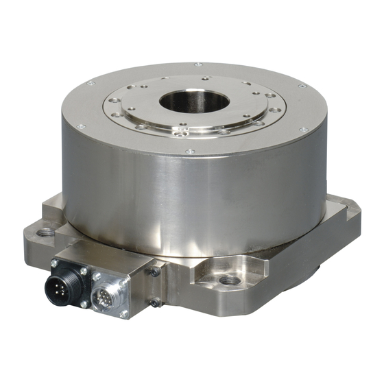
Page 8: Parts Identification
Parts identification Rotor (output shaft) Z-phase mark Encoder connector Power connector Power supply (U/V/W) Grounding ( Instructions on storage Precautions Note the following when storing the direct drive motor for an extended period of time (guideline: three months or longer). •... -
Page 9: Chapter 2 Installation
INSTALLATION Precautions • The cables should not be damaged, stressed, loaded, or pinched. • Install the direct drive motor on incombustible material. Installing them directly or close to combustibles will lead to smoke or a fire. • Provide an adequate protection to prevent screws and other conductive matter, oil and other combustible matter from entering the direct drive motor. -
Page 10: Equipment Configuration
Equipment configuration The following shows the configuration of a direct drive motor. When using the direct drive motor, note the following. Minimum oscillation angle For a direct drive motor that performs a rotating oscillating motion within 70 °, rotate the motor more than 90 ° at least once a day to keep the bearings lubricated. -
Page 11: Mounting Direction
Mounting direction The mounting direction of the direct drive motor is shown in the following table. Direct drive motor series Mounting direction TM-RFM All directions TM-RG2M TM-RU2M Load mounting/dismounting precautions • To prevent a malfunction on the encoder, the rotor must not be hammered during assembling. •... -
Page 12: Protection From Oil And Water
Protection from oil and water Provide adequate protection to prevent foreign matter such as oil and water from entering the rotor of the direct drive motor. When mounting the direct drive motor, consider the items in this section. • Do not use the rotary servo motor with its cable soaked in oil or water. Cover Direct drive motor Oil/water pool... -
Page 13: Parts Having Life
Parts having life The life of the following parts is listed below. If any fault is found in the parts, replace them immediately because their life varies. For parts replacement, contact your local sales office. Part name Guideline of life Remark Bearings 20,000 hours to 30,000 hours... -
Page 14: Flange Size
Flange size The rated torque of the direct drive motor is the continuous permissible torque value that can be generated when the direct drive motor is mounted on the flange specified in this table, made of aluminum, and used in the environment of 0 ˚C to 40 ˚C ambient temperature. -
Page 15: Chapter 3 Connectors Used For Direct Drive Motor Wiring
CONNECTORS USED FOR DIRECT DRIVE MOTOR WIRING Precautions • The IP rating indicated is the connector's protection against ingress of dust and water when the connector is connected to a servo amplifier, direct drive motor, or absolute position storage unit. •... -
Page 16: Wiring Connectors (Connector Configurations A/B/C/D/E)
Wiring connectors (connector configurations A/B/ C/D/E) Plug Cord clamp Connector Feature Plug (Hirose Electric) Recommended cable (Bando Direct drive motor configuration Densen) encoder connector or absolute position Type Plug Cord clamp Model Cable OD storage unit [mm] connector (servo (reference) amplifier side) IP67 Straight... - Page 17 Plug Cable clamp Connector Feature Plug (DDK) Cable clamp (DDK) Direct drive motor configuration power supply Type Model Cable OD [mm] Model connector (reference) IP67 Straight CE05-6A18-10SD-D-BSS 8.5 to 11 CE3057-10A-2-D CE05-2A18-10PD-D Applicable wire size: AWG 14 to 12 10.5 to 14.1 CE3057-10A-1-D compliant General...
-
Page 18: Chapter 4 Connector Dimensions
CONNECTOR DIMENSIONS The following shows the dimensions of the connectors used for wiring the direct drive motor. Hirose Electric ■RM15WTPZK-12S/RM15WTPZ-12P(72) Model Connector configuration RM15WTPZK-12S RM15WTPZ-12P(72) *1 Refer to the following for the connector configuration. Page 14 Wiring connectors (connector configurations A/B/C/D/E) [Unit: mm] Spanner hook gap dimension: 18 M19 ×... - Page 19 ■CE05-6A14S-2SD-D Refer to the following connector configuration B for the connector configuration. Page 14 Wiring connectors (connector configurations A/B/C/D/E) [Unit: mm] (13.2) 7/8-20UNEF-2B Positioning key 3/4-20UNEF-2A 24.0 ± 1 5.6 ± 0.1 8.46 ± 0.5 ■CE05-6A18-10SD-D-BSS, CE05-6A22-22SD-D-BSS, CE05-6A32-17SD-D-BSS [Unit: mm] Positioning key Model C ±...
- Page 20 ■CE3057-10A-1-D, CE3057-10A-2-D, CE3057-12A-1-D, CE3057-12A-2-D, CE3057-20A-1-D [Unit: mm] A ± 0.7 V-thread φE (Bushing OD) Model Applicable Enclosed Applicable Connector shell size bushing cable OD configuration model (reference) CE3057-10A-1- 23.8 30.1 10.3 (41.3) 15.9 14.1 31.7 1-20UNEF- CE3420-10-1 10.5 to 14.1 CE3057-10A-2- 11.0 CE3420-10-2...
- Page 21 ■D/MS3057-6A, D/MS3057-10A, D/MS3057-12A, D/MS3057-20A [Unit: mm] A ± 0.7 φE (Bushing ID) Effective thread length C φD (Cable clamp ID) Model Shell size Bushing Connector configuration D/MS3057-6A 22.2 24.6 10.3 11.2 27.0 3/4-20UNEF AN3420-6 D/MS3057-10A 23.8 30.1 10.3 15.9 14.3 31.7 1-20UNEF AN3420-10...
- Page 22 Nippon Flex [Unit: mm] (1) *1 (2) *1 Screw C Model Screw C Applicable φd Tightening nut Nipple body Connector cable OD configuration Two- Width Number Two- Width Number face across face across width corners corners width corners corners ACS- 3/4- 4.0 to 8.0 15.0...
-
Page 23: Chapter 5 Connection Of Servo Amplifier And Direct Drive Motor
CONNECTION OF SERVO AMPLIFIER AND DIRECT DRIVE MOTOR Precautions • Insulate the conductive parts of the terminals. • To prevent an unexpected operation of the direct drive motor, wire the equipment correctly and securely. • Make sure to connect the cables and connectors by using the fixing screws and the locking mechanism. Otherwise, the cables and connectors may be disconnected during operation. -
Page 24: Precautions For Wiring
Precautions for wiring Precautions • To avoid a malfunction, connect the power phases (U/V/W) of the servo amplifier and the direct drive motor correctly. • To prevent a malfunction, do not connect AC power supply directly to the direct drive motor. Refer to the following for the encoder cable. -
Page 25: Selection Example Of Wires
Selection example of wires Wires indicated in this section are separated wires. Selection conditions of wire size are as follows. • Construction condition: Single wire set in midair • Wiring length: 30 m or shorter Wire size selection examples for the 600 V Grade heat-resistant polyvinyl chloride insulated wire (HIV wire) are indicated below. -
Page 26: Chapter 6 Wiring Option
Wiring option Precautions • To prevent malfunction and a fire, use the specified peripheral equipment and options. • To prevent an electric shock, fire, or injury, correctly wire options and peripheral equipment, etc. in the correct combination. • We recommend using HIV wires to wire the servo amplifiers, direct drive motors, options, and peripheral equipment. Therefore, the recommended wire sizes may differ from those of the used wires for the previous direct drive motors. -
Page 27: Combinations Of Connector Sets
Combinations of connector sets MR-J5 1-axis servo amplifier MR-J5 1-axis MR-J5 1-axis servo amplifier servo amplifier (2) (3) CNP3 For incremental system For absolute position detection system Power connector Encoder connector Absolute position storage unit MR-BTAS01 For absolute position detection system Direct drive motor TM-RFM TM-RG2M... - Page 28 MR-J5 multi-axis servo amplifier MR-J5 multi-axis servo amplifier (2) (3) For incremental system For absolute position detection system MR-J5 multi-axis servo amplifier Power connector CNP3A CNP3B Encoder connector CN2A CNP3C Absolute position storage unit CN2B MR-BTAS01 CN2C Direct drive motor TM-RFM For absolute position detection system TM-RG2M...
-
Page 29: Connector List
Connector list Product Model Description Connectable Remark name direct drive motor Power MR-PWCNF For TM-RFM_C20 IP67 connector set For TM-RFM_E20 For TM- compliant RG2M_C30 Plug: CE05-6A14S-2SD-D (DDK) For TM- Cable clamp: YSO14-9 to 11 (Daiwa Dengyo) RG2M_E30 Applicable cable For TM- Applicable wire size: 0.3 mm to 1.25 mm (AWG 22 to 16) -
Page 30: Encoder Connector Set
Encoder connector set The encoder cable should be fabricated by the customer. Refer to the following for fabrication. Page 28 MR-J3DDCNS Page 28 MR-J3DDSPS Page 29 Combinations of encoder cables For fabrication, refer to the following wiring diagram. Page 30 Fabrication of the encoder cable Fabricate the encoder cable to be 50 m or shorter between the servo amplifier and the direct drive motor. -
Page 31: Combinations Of Encoder Cables
■Absolute position storage unit-side connector Plug: RM15WTPZ-12P(72) Cord clamp: JR13WCCA-8(72) (Hirose Electric) ■Encoder-side connector Plug: RM15WTPZK-12S Cord clamp: JR13WCCA-8(72) (Hirose Electric) Combinations of encoder cables For incremental system MR-J5 1-axis servo amplifier 50 m or less Encoder cable A Direct drive motor TM-RFM TM-RG2M TM-RU2M... -
Page 32: Fabrication Of The Encoder Cable
For absolute position detection system MR-J5 1-axis servo amplifier 20 m or less Direct drive motor Encoder cable B Encoder cable C TM-RFM TM-RG2M TM-RU2M MR-J5 multi-axis servo amplifier CN2A Absolute position CN2B storage unit CN2C MR-BTAS01 *1 Refer to the following for details. Page 32 Detail of the encoder cable B connector *2 Refer to the following for details. - Page 33 ■Encoder-side connector (2) Straight plug: RM15WTPZK-12S Cord clamp: JR13WCCA-8(72) (Hirose Electric) Recommended cable: 20276 VSVPAWG#23×6P KB-0492 (Bando Densen) THM2 THM1 View from the wiring side. *1 Do not connect anything to the pins shown with a diagonal line. *2 Supplier: Toa Electric Industrial Encoder cable A cable internal wiring diagram (1) CN2, CN2A, CN2B, and (2) Encoder-side...
- Page 34 Detail of the encoder cable B connector ■CN2, CN2A, CN2B, and CN2C side connector (3) Receptacle: 36210-0100PL Shell kit: 36310-3200-008 (3M) THM2 THM1 View from the wiring side. Connector set: 54599-1019 (Molex) THM2 THM1 View from the wiring side. *1 Do not connect anything to the pins shown with a diagonal line. Refer to the following. Page 35 Shield procedure of CN2, CN2A, CN2B, and CN2C side connectors ■Absolute position storage unit-side connector (4) Straight plug: RM15WTPZK-12S...
- Page 35 Encoder cable B cable internal wiring diagram When the distance between the servo amplifier and the direct drive motor is within 20 m (3) CN2, CN2A, CN2B, and (4) Absolute position storage CN2C side connector unit side connector THM1 THM1 THM2 THM2 Plate...
- Page 36 ■Encoder-side connector (6) Straight plug: RM15WTPZK-12S Cord clamp: JR13WCCA-8(72) (Hirose Electric) Recommended cable: 20276 VSVPAWG#23×6P KB-0492 (Bando Densen) THM2 THM1 View from the wiring side. *1 Do not connect anything to the pins shown with a diagonal line. *2 Supplier: Toa Electric Industrial Encoder cable C cable internal wiring diagram When the distance between the servo amplifier and the direct drive motor is within 20 m (5) Absolute position storage...
-
Page 37: Shield Procedure Of Cn2, Cn2A, Cn2B, And Cn2C Side Connectors
Shield procedure of CN2, CN2A, CN2B, and CN2C side connectors For CN2, CN2A, CN2B, and CN2C side connectors, securely connect the external conductor of the shielded cable to the ground plate and fix it to the connector shell. Cable Ground plate Screw 6 Wiring option 6.2 Encoder connector set... -
Page 38: Absolute Position Storage Unit Mr-Btas01
Absolute position storage unit MR-BTAS01 Precautions • If the absolute position storage unit MR-BTAS01 is replaced, the absolute position is erased. For details, refer to "Absolute position detection system" in the following manual. MR-J5 User's Manual (Hardware) • If the encoder cable is disconnected, [AL. 025 Absolute position erased] occurs. Connection method with the encoder cable Page 30 For absolute position detection system Dimensions... -
Page 39: Chapter 7 Tm-Rfm Series
TM-RFM SERIES This chapter provides information on the direct drive motor specifications and characteristics. When using the TM-RFM series direct drive motor, always read the Safety Instructions in the beginning of this manual in addition to this chapter. Model designation The following describes model designation. -
Page 40: Combinations Of Servo Amplifier And Direct Drive Motor
Combinations of servo amplifier and direct drive motor 1-axis servo amplifier : Standard torque Direct drive motor Servo amplifier MR-J5-_ 20G/A 40G/A 60G/A 70G/A 100G/A 350G/A TM-RFM002C20 TM-RFM004C20 ... -
Page 41: Specification List
Specification list TM-RFM series Item TM-RFM SERIES 002C20 004C20 006C20 006E20 012E20 018E20 Motor OD (frame OD) [mm] φ130 φ180 Power supply capacity Refer to "Power supply capacity and generated loss" in the following manual. MR-J5 User's Manual (Hardware) Continuous running duty Rated output [W] Rated torque [N•m] Maximum torque [N•m]... - Page 42 Item TM-RFM SERIES 012G20 048G20 072G20 040J10 120J10 Motor OD (frame OD) [mm] φ230 φ330 Power supply capacity Refer to "Power supply capacity and generated loss" in the following manual. MR-J5 User's Manual (Hardware) Continuous running duty Rated output [W] 1005 1508 1257...
- Page 43 *1 When the power supply voltage drops, the output and the rated speed cannot be guaranteed. *2 If the load to motor inertia ratio exceeds the indicated value, contact your local sales office. *3 To configure the absolute position detection system, connect to battery unit and absolute position storage unit. Refer to the following for absolute position storage unit.
-
Page 44: Torque Characteristics
Torque characteristics For the machine where the unbalanced torque occurs, such as a vertical axis system (lift), use the absolute position detection system. Page 8 For vertical axis (lift) The unbalanced torque of the machine should be kept at 70 % or lower of the motor's rated torque. : 3-phase 200 VAC and 1-phase 230 VAC : 1-phase 200 VAC The single-phase power input is for TM-RFM002C20, TM-RFM004C20, TM-RFM006C20, TM-RFM006E20, TM-RFM012E20,... -
Page 45: Dimensions
Dimensions Since the actual dimensions may be approximately 3 mm larger than the drawing dimensions at a maximum, allow some margin when designing the machine side. indicates the rotor. TM-RFM002C20, TM-RFM004C20, TM-RFM006C20 Model Variable dimensions L TM-RFM002C20 58.5 TM-RFM004C20 75.5 TM-RFM006C20 92.5 6-M5... -
Page 46: Tm-Rfm006E20, Tm-Rfm012E20, Tm-Rfm018E20
TM-RFM006E20, TM-RFM012E20, TM-RFM018E20 Model Variable dimensions L TM-RFM006E20 TM-RFM012E20 TM-RFM018E20 6-M5 4-φ14 mounting hole Screw hole depth 8 Use hexagon socket head cap screw. □180 (PE) Power connector output shaft side Detailed view of A [Unit: mm] 7 TM-RFM SERIES 7.5 Dimensions... -
Page 47: Tm-Rfm012G20, Tm-Rfm048G20, Tm-Rfm072G20
TM-RFM012G20, TM-RFM048G20, TM-RFM072G20 Model Variable dimensions L TM-RFM012G20 TM-RFM048G20 TM-RFM072G20 6-M6 4-φ14 mounting hole screw hole depth10 Use hexagon socket head cap screw. □230 2×2-M10 screw hole depth19.5 (PE) Power connector output shaft side 19.5 Detailed view of A [Unit: mm] Arrow B 7 TM-RFM SERIES 7.5 Dimensions... -
Page 48: Tm-Rfm040J10, Tm-Rfm120J10
TM-RFM040J10, TM-RFM120J10 Model Variable dimensions TM-RFM040J10 88.5 TM-RFM120J10 162.5 4-φ18 mounting hole 6-M8 Use hexagon socket screw hole depth13 head cap screw. □330 2×2-M12 Screw hole depth25.5 Encoder connector 32.5 RM15WTRZB-12P(72) (PE) Power connector CE05-2A22-22PD-D (TM-RFM040J10, TM-RFM120J10) Power connector output shaft side Detailed view of A 16.5 [Unit: mm]... -
Page 49: Chapter 8 Tm-Rg2M Series/Tm-Ru2M Series
TM-RG2M SERIES/TM-RU2M SERIES This chapter provides information on the direct drive motor specifications and characteristics. When using the TM-RG2M series or TM-RU2M series direct drive motor, always read the Safety Instructions in the beginning of this manual in addition to this chapter. -
Page 50: Combinations Of Servo Amplifier And Direct Drive Motor
Combinations of servo amplifier and direct drive motor By combining with a servo amplifier with larger capacity, the maximum torque can be increased to 400 %. 1-axis servo amplifier : Standard torque : Torque increased Direct drive motor Servo amplifier MR-J5-_ 20G/A 40G/A ... -
Page 51: Specification List
Specification list TM-RG2M series/RU2M series Item TM-RG2M series/RU2M series 002C30 004E30 009G30 Motor OD (frame OD) [mm] φ130 φ180 φ230 Power supply capacity Refer to "Power supply capacity and generated loss" in the following manual. MR-J5 User's Manual (Hardware) Continuous running duty Rated output [W] 141 (188) Rated torque [N•m]... - Page 52 *1 When the power supply voltage drops, the output and the rated speed cannot be guaranteed. *2 If the load to motor inertia ratio exceeds the indicated value, contact your local sales office. *3 To configure the absolute position detection system, connect to battery unit and absolute position storage unit. Refer to the following for absolute position storage unit.
-
Page 53: Torque Characteristics
Torque characteristics For the machine where the unbalanced torque occurs, such as a vertical axis system (lift), use the absolute position detection system. Page 8 For vertical axis (lift) The unbalanced torque of the machine should be kept at 70 % or lower of the motor's rated torque. : 3-phase 200 VAC and 1-phase 230 VAC : 1-phase 200 VAC [TM-RG2M002C30]... -
Page 54: Dimensions
Dimensions Since the actual dimensions may be approximately 3 mm larger than the drawing dimensions at a maximum, allow some margin when designing the machine side. indicates the rotor. TM-RG2M002C30 4-φ9 mounting hole Use hexagon socket □130 head cap screw. 6-M5 screw hole depth 8 Encoder connector Power connector... -
Page 55: Tm-Rg2M009G30
TM-RG2M009G30 4-φ14 mounting hole 6-M5 screw hole depth 8 Use hexagon socket □230 head cap screw. Power connector Encoder connector (PE) RM15WTRZB-12P(72) CE05-2A14S-2PD-D Power connector output shaft side Arrow A [Unit: mm] TM-RU2M002C30 4-φ9 mounting hole Use hexagon socket 2-φ6H7 depth 8 □130 head cap screw. -
Page 56: Tm-Ru2M004E30
TM-RU2M004E30 4-φ14 mounting hole 2-φ6H7 depth 8 Use hexagon socket P.C.D.205 ± 0.03 head cap screw. □180 6-M5 Screw hole depth 8 Encoder connector Power connector RM15WTRZB-12P(72) CE05-2A14S-2PD-D (PE) Power connector output shaft side Arrow A [Unit: mm] TM-RU2M009G30 4-φ14 mounting hole 6-M5 screw hole depth 8 Use hexagon socket □230... -
Page 57: Chapter 9 Compliance With Each Region
COMPLIANCE WITH EACH REGION Compliance with CE marking CE marking The CE marking is mandatory and must be affixed to specific products placed on the European Union. When a product conforms to the requirements, the CE marking must be affixed to the product. CE marking also incorporates the machines and equipments that are for sale with the servo motors in the European Union area. -
Page 58: Compliance With Ul/Csa Standard
Compliance with UL/CSA standard Use the direct drive motor that complies with the UL/CSA standard. For the latest information of compliance, contact your local sales office. Unless otherwise specified, the handling, performance, specifications, and others of the UL/CSA compliant products are the same as those of the standard models. - Page 59 Selection example of wires To comply with UL 1004-1 and CSA-C22.2 No. 100, use UL certified 75 ˚C rated copper wires for wiring. The following table shows the 75 ˚C rated wire size [AWG] , which is used for wiring of TM-RFM, TM-RG2M, and TM-RU2M series.
-
Page 60: Chapter 10 Appendix
APPENDIX 10.1 Fabrication of the encoder cable Use recommended encoder cable connectors indicated in chapter 3 and chapter 4. When fabricating an encoder cable, note the descriptions in chapter 9 to ensure reliability of communication. Fabricate cables with the following procedure. Selection of connectors •... - Page 61 MEMO 10 APPENDIX 10.1 Fabrication of the encoder cable...
-
Page 62: Revisions
First edition This manual confers no industrial property rights of any other kind, nor does it confer any patent licenses. Mitsubishi Electric Corporation cannot be held responsible for any problems involving industrial property rights which may occur as a result of using the contents noted in this manual. -
Page 63: Warranty
WARRANTY Warranty 1. Warranty period and coverage We will repair any failure or defect hereinafter referred to as "failure" in our FA equipment hereinafter referred to as the "Product" arisen during warranty period at no charge due to causes for which we are responsible through the distributor from which you purchased the Product or our service provider. -
Page 64: Trademarks
TRADEMARKS MELSERVO is a trademark or registered trademark of Mitsubishi Electric Corporation in Japan and/or other countries. All other product names and company names are trademarks or registered trademarks of their respective companies. SH(NA)-030318ENG-A... - Page 66 SH(NA)-030318ENG-A(1907)MEE MODEL: MODEL CODE: HEAD OFFICE : TOKYO BUILDING, 2-7-3 MARUNOUCHI, CHIYODA-KU, TOKYO 100-8310, JAPAN NAGOYA WORKS : 1-14 , YADA-MINAMI 5-CHOME , HIGASHI-KU, NAGOYA , JAPAN When exported from Japan, this manual does not require application to the Ministry of Economy, Trade and Industry for service transaction permission. Specifications are subject to change without notice.
Need help?
Do you have a question about the MELSERVO-J5 TM-RG2M Series and is the answer not in the manual?
Questions and answers