
Subscribe to Our Youtube Channel
Related Manuals for Johnson Controls CIS01


Summary of Contents for Johnson Controls CIS01
- Page 1 Installation & Maintenance Manual Simplifi ed Wired Controller Model: CIS01 IMPORTANT: READ AND UNDERSTAND THIS MANUAL BEFORE USING THIS CONTROLLER. KEEP THIS MANUAL FOR FUTURE REFERENCE. P5415520...
-
Page 3: Table Of Contents
TABLE OF CONTENTS Important Notice ........................... 2 Product Inspection upon Arrival ....................2 1. Safety Summary ........................2 2. Brand Label ..........................5 3. Installation Work........................5 4. Electrical Wiring ........................6 5. Checking Procedures ....................... 7 6 Function Selection and Input/Output Setting from Controller ........... 8 7. -
Page 4: Important Notice
● Johnson Controls Inc. pursues a policy of continuing improvement in design and performance in its products. As such, Johnson Controls Inc. reserves the right to make changes at any time without prior notice. ● Johnson Controls Inc. cannot anticipate every possible circumstance that might involve a potential hazard. - Page 5 Use only Johnson Controls recommended, provided as standardized, or replacement parts. ● Johnson Controls shall will not assume any liability for injuries or damage caused by not following steps outlined or described in this manual. Unauthorized modifi cations to Johnson Controls products are prohibited as they…...
- Page 6 Electrical Precautions Take the following precautions to reduce the risk of electric shock, fi re or explosion resulting in serious injury or death: ● Only use electrical protection equipment and tools suited for this installation. ● Insulate the controller against moisture and temperature extremes. ●...
-
Page 7: Brand Label
Check the boxes below as you complete each item. 2. Brand Label Select the accessory brand label according to the production order. Attach the accessory brand logo label to “This Area”. This Area 3. Installation Work [3.1 Selection of Installation Place] 1) Select a suitable place for handling and determine the installation place of the controller with the customer’s acceptance. -
Page 8: Electrical Wiring
When shielded cabling is applied, proper bonding and termination of the cable shield is required as per Johnson Controls guidelines. Plenum and riser ratings for communication cables must be considered per application and local code requirements. -
Page 9: Checking Procedures
NOTICE A. Use AWG 22 (0.32mm ) to AWG 18 (0.82mm ) cable with a maximum total cable length 98.4 ft. (30m). If the total cable length is longer than 98.4 ft. (30m), use communication cable of 1P to AWG 18 (0.82mm Maximum total cable length 1640.5 ft. -
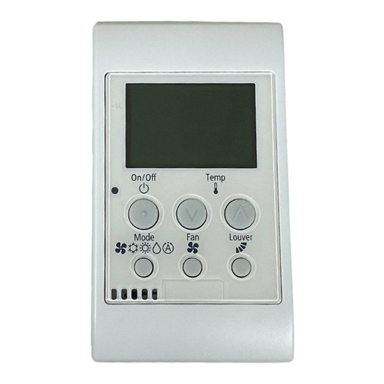
Page 10: Function Selection And Input/Output Setting From Controller
6. Function Selection and Input/Output Setting from Controller (1) Press and hold “ ” for “Temp” and “Fan” simultaneously for at least 3 seconds during the normal mode (when unit is not operated). (2) Select the optional mode by pressing “ ” or “ ” for “Temp” 01: Function Selection and press “Fan”. - Page 11 Table A Optional Setting Items for Function Selection Individual Setting Items Optional Function Contents Setting Setting Condition Standard (Set Temp. +7 F (+4 Cancellation of Heating Removal (Set Temp.) ○ Temperature Compensation Set Temp. +3 F (+2 C) (*1) due to Uneven Heat Load Set Temp.
- Page 12 Individual Setting Items Optional Function Contents Setting Setting Condition Not Available ○ Power Supply ON/OFF 2 Available Not Prepared Not Used (Use as 00 setting conditions) Prevention for Heating Discharge Air Not Available ○ Temp. Decrease Available Not Prepared Not Used (Use as 00 setting conditions) Not Prepared Not Used Not Prepared...
- Page 13 Individual Setting Items Optional Function Contents Setting Setting Condition 62 (17) F (17 64 (18) F (18 66 (19) F (19 68 (20) F (20 70 (21) F (21 C) (Factory-Setting) 72 (22) F (22 Automatic Reset Temperature 74 (23) F (23 ×...
- Page 14 Individual Setting Items Optional Function Contents Setting Setting Condition No Setting (Factory Default) Remote Control Run/Stop × RC Run/Stop Operation Prohibited Prohibit by Central Controller (*9) RC Run Operation Prohibited Not Prepared Not Used (Use as 00 setting conditions) Not Prepared Not Used (Use as 00 setting conditions) Not Prepared Not Used (Use as 00 setting conditions)
- Page 15 Individual Setting Items Optional Function Contents Setting Setting Condition Not Prepared Not Used (Use as 00 setting conditions) Not Prepared Not Used (Use as 00 setting conditions) Not Prepared Not Used (Use as 00 setting conditions) Auxiliary Heater at Defrosting ○...
- Page 16 Individual Setting Items Optional Function Contents Setting Setting Condition 2(1.0) F (1.0 3(1.5) F (1.5 Cooling/Heating Changeover × 4(2.5) F (2.5 Temperature 5(3.0) F (3.0 1(0.5) F (0.5 4(2.5) F (2.5 5(3.0) F (3.0 6(3.5) F (3.5 7(4.0) F (4.0 8(4.5) F (4.5 ×...
- Page 17 Table B Input and Output Number Display and Connectors Input Number Display Factory Setting Port Setting Input/Output Indication Setting Item Indication Input 1 CN3 1-2 Remote ON/OFF 1 (Level) Input 2 CN3 2-3 Prohibiting Remote Control after Manual Stoppage Output 1 CN7 1-2 Operation Output 2...
-
Page 18: Check Mode
7. Check Mode Check 1: Sensor condition of the air conditioner is monitored and indicated. Check 2: Sensor data of the air conditioner prior to alarm occurrence is indicated. (1) Press and hold “ ”, “ ” for “Temp” and “Fan” simultaneously for at least 3 seconds during the normal mode. - Page 19 P5415520...
- Page 20 © 2018 Johnson Controls, Inc. P5415520-rev.3 LIT-12012037 Issued December, 2018...
Need help?
Do you have a question about the CIS01 and is the answer not in the manual?
Questions and answers