Advertisement
Quick Links
Model:
TOOLS REQUIRED:
1. Power Screwdriver
• Phillips #3 Bit - floor panel screws
2. Panel Lifter (Suction Cups) - remove
floor panels
3. Voltmeter - confirm power status
MATERIALS REQUIRED:
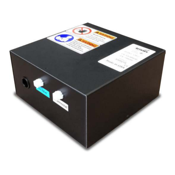
1. CB2 Control Box
2. Plug & Play Cables (PAP-1J)
PREPARATION:
1. Verify that the CB2 is the correct model, unit count and
location(s) per scheduled placement.
2. Remove the floor covering / floor panel at the desired
location(s) (if installed).
3. Verify that all adjacent floor panels are properly installed.
INSTALLATION:
Connect CB2 to designated thermostatic zone:
• Thermostat terminal connects to PAP-7B with the
included PAP-1J cable
• Air Valve terminal connects to the MIT3 air valves on
the trough with a PAP-1 cable
• Water valve connections are made to terminal blocks
inside the CB2 box
Refer to job-specific Zone Cabling Diagrams for details.
EXAMPLE ZONE:
T = Thermostat
CB = CB2 Control Box
CLWMIT = Hydronic Linear Terminal with Air Valve Generation 3
PM = Power Module
PM
LINE VOLTAGE
©2016 Johnson Controls | The performance specifications are nominal and conform to acceptable industry standards. For applications at conditions beyond these specifications, consult the local
Johnson Controls office. Johnson Controls, Inc. shall not be liable for damages resulting from misapplication or misuse of its products.
FlexSys
WATER
VALVE
CLWMIT
IN
OUT
PAP-5 (GREEN)
Installation / Operation Manual
Control Box
CB2
OPERATION:
Refer to Sequence of Operation on Page 2.
MAINTENANCE:
Once installed, the CB2 requires no regular service
or maintenance for proper operation.
IN
OUT
PAP-1J (BLUE)
1
T
PAP-7B (WHITE)
PAP-1J (BLUE)
T-STAT
CB
A/V
PAP-1 (BLUE)
CLWMIT
IN
OUT
PAP-1 (BLUE)
PAP-1J (BLUE)
© 2016 AirFixture, LLC
V160811
IN
OUT
Advertisement

Related Manuals for Johnson Controls FlexSys CB2


Summary of Contents for Johnson Controls FlexSys CB2
- Page 1 LINE VOLTAGE ©2016 Johnson Controls | The performance specifications are nominal and conform to acceptable industry standards. For applications at conditions beyond these specifications, consult the local Johnson Controls office. Johnson Controls, Inc. shall not be liable for damages resulting from misapplication or misuse of its products.
- Page 2 • Heat LED blinks during lower Heat Demand until WV is fully open ©2016 Johnson Controls | The performance specifications are nominal and conform to acceptable industry standards. For applications at conditions beyond these specifications, consult the local Johnson Controls office. Johnson Controls, Inc. shall not be liable for damages resulting from misapplication or misuse of its products.
Need help?
Do you have a question about the FlexSys CB2 and is the answer not in the manual?
Questions and answers