Johnson Controls Mercury P2000 Hardware Installation
Security management system
Hide thumbs
Also See for Mercury P2000:
- Manual (110 pages) ,
- Configuration (86 pages) ,
- Hardware installation (37 pages)

Related Manuals for Johnson Controls Mercury P2000


Summary of Contents for Johnson Controls Mercury P2000
- Page 1 P2000 Security Management System hardware installation CKM-EP1502 authentic Mercury™ controller 24-10707-15 Revision E December 2017...
- Page 2 If this document is translated from the original English version by Johnson Controls, all reasonable endeavors will be used to ensure the accuracy of translation. Johnson Controls shall not be liable for any translation errors contained herein or for incidental or consequential damages in connection with the furnishing or use of this translated material.
- Page 3 Declarations of Conformity United States: This equipment has been tested and found to comply with the limits for a Class A digital device, pursuant to part 15 of the FCC Rules. These limits are designed to provide reasonable protection against harmful interference when the equipment is operated in a commercial environment.
- Page 4 UNDERWRITERS LABORATORIES COMPLIANCE VERIFICATION SHEET The following model number is listed under Underwriters Laboratories® (UL) 1076 for Proprietary Burglar Alarm Units and Systems, UL 294 for Access Control Systems Units and Underwriters Laboratories of Canada ULC/ORD-C1076-86. CKM-EP1502 When installed at the site the following requirements must be met to comply with these standards. 1.
- Page 5 CKM-EP1502 Hardware Installation Manual 24-10707-15 Rev. E CKM-EP1502 C ONTROLLER This document provides hardware installation and setup instructions for CKM-EP1502, the authentic Mercury™ intelligent dual reader controller. This document is divided into the following sections: • General Information on page 1 •...
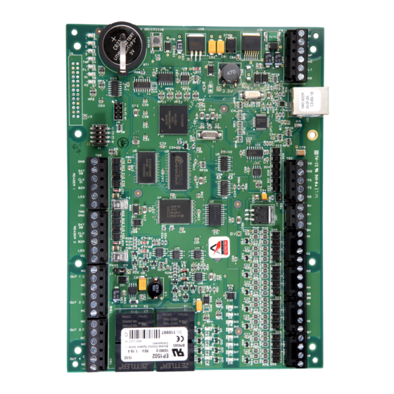
- Page 6 CKM-EP1502 Hardware Installation Manual 24-10707-15 Rev. E OUNTING NFORMATION Figure 1: CKM-EP1502 Hardware...
-
Page 7: Wiring Information
CKM-EP1502 Hardware Installation Manual 24-10707-15 Rev. E IRING NFORMATION This sections covers the following: • Cable Routing • Input Power, Cabinet Tamper, and UPS Fault Input Wiring • Communication Wiring • Reader Wiring • Input Circuit Wiring • Relay Circuit Wiring Cable Routing The cables should run in grounded conduit or at least two feet from AC power, fluorescent lights, or other high energy sources. - Page 8 CKM-EP1502 Hardware Installation Manual 24-10707-15 Rev. E Input Power, Cabinet Tamper, and UPS Fault Input Wiring The CKM-EP1502 requires 12-24 VDC power. Locate power source as close to the unit as possible. : Connect power with minimum of 18 AWG wire. Connect the GND MPORTANT signal to earth ground in one location within the system.
- Page 9 CKM-EP1502 Hardware Installation Manual 24-10707-15 Rev. E Figure 3: CKM-EP1502 Communications Wiring Reader Wiring Each reader port supports Wiegand, magnetic stripe, and two-wire RS- 485 electrical interfaces. Power to the reader is selectable: 12 VDC (VIN must be greater than 20 VDC), or power is passed through (PT) from the input voltage of the CKM-EP1502 (TB1-VIN) and is current limited to 150 mA for each reader port.
- Page 10 CKM-EP1502 Hardware Installation Manual 24-10707-15 Rev. E Input Circuit Wiring Typically, you use these inputs to monitor door position, request to exit, or alarm contacts. You can configure input circuits as unsupervised or supervised. When request to exit (REX) input is supervised, the strike remains locked when a transition to open state or short state occurs.
- Page 11 CKM-EP1502 Hardware Installation Manual 24-10707-15 Rev. E Relay Circuit Wiring Four relays with Form-C contacts are provided for controlling door lock mechanisms or alarm signaling. The relay contacts are rated at 5 A at 30 VDC, dry contact configuration. Each relay has a Common pole (C), a Normally Open pole (NO) and a Normally Closed pole (NC).
-
Page 12: Setup Information
CKM-EP1502 Hardware Installation Manual 24-10707-15 Rev. E ETUP NFORMATION Jumpers to set up the port interface and end of line termination. Use the four DIP Switches on S1 to configure the processor operating mode. DIP switches are read on power-up except where noted. Pressing switch S2 resets the controller. - Page 13 CKM-EP1502 Hardware Installation Manual 24-10707-15 Rev. E Table 1: Connections Connection Symbol Description Reader 1 GND: Ground DAT/D0: Data/Data 0/TR- CLK/D1: Clock/Data 1/TR+ BZR: Reader Buzzer LED: Reader LED VO: Reader Power Reader 2 GND: Ground DAT/D0: Data/Data 0/TR- CLK/D1: Clock/Data 1/TR+ BZR: Reader Buzzer LED: Reader LED VO: Reader Power...
- Page 14 CKM-EP1502 Hardware Installation Manual 24-10707-15 Rev. E Table 2: Jumpers Jumper Set at Description Factory Use Only 10Base-T/100Base-Tx Ethernet Connection (Port 0) Factory Use Only Factory Use Only Port 2 (TB3) RS-485 EOL Terminator is Off Port 2 (TB3) RS-485 EOL Terminator is On Factory Use Only Reader Power Select 12 VDC at Reader Ports...
- Page 15 CKM-EP1502 Hardware Installation Manual 24-10707-15 Rev. E : In the factory or OEM default modes, downloaded configuration/ MPORTANT database is not saved to flash memory. Table 4: Factory Default Communication Parameters Setting Value Network Static IP address 192.168.0.251 Communication address Primary Host port IP server, no encryption, port 3001 Alternate Host Port 1...
- Page 16 CKM-EP1502 Hardware Installation Manual 24-10707-15 Rev. E DHCP) DDRESSING ONFIGURATION TATIC The CKM-EP1502 controller uses two addressing modes: static IP addresses or public DHCP. This section provides information on how to set up either addressing mode. For the controller’s default communication parameters, see Table : If you are using static IP addressing mode, assign a unique IP address setting to the controller before connecting it to the network, to avoid IP...
- Page 17 CKM-EP1502 Hardware Installation Manual 24-10707-15 Rev. E To configure network address: 1. In the Configuration Manager, click Network. 2. In Network Settings: • For the DHCP mode select Use DHCP method to obtain IP address automatically and specify the host name, or •...
-
Page 18: Status Leds
CKM-EP1502 Hardware Installation Manual 24-10707-15 Rev. E TATUS Table 5: LED Information Process LED Information Power-up All LEDs OFF Initialization LEDs 1, 2, 3, TMP, FLT, R1, R2, and IN1 through IN8 are sequenced during initialization. LEDs 1, 3, and TMP are turned ON for approximately 4 seconds after the hardware initialization completes, and then the application code initializes. -
Page 19: Specifications
CKM-EP1502 Hardware Installation Manual 24-10707-15 Rev. E Table 6: LED Description Description Input IN1 Status: OFF = Inactive, ON = Active, Flash = Trouble Input IN2 Status: OFF = Inactive, ON = Active, Flash = Trouble Input IN3 Status: OFF = Inactive, ON = Active, Flash = Trouble Input IN4 Status: OFF = Inactive, ON = Active, Flash = Trouble Input IN5 Status:... - Page 20 CKM-EP1502 Hardware Installation Manual 24-10707-15 Rev. E Table 7: CKM-EP1502 Specifications Category Description Reader Interface Reader Power 12 VDC±10% regulated, current limited to 150 mA for each reader, or (jumper selectable) 12 to 24 VDC±10% (input voltage passed through) current limited to 150 mA for each reader.
-
Page 21: Maintenance
CKM-EP1502 Hardware Installation Manual 24-10707-15 Rev. E AINTENANCE Impaired Performance The following is a list of the impaired performance conditions: • Unit environment not as specified • Unit power not as specified • Cable type and length not as specified Test Procedure To check for proper operation of the device: 1. - Page 22 CKM-EP1502 Hardware Installation Manual 24-10707-15 Rev. E : Before you replace the lithium battery (annually or after extended use), ensure AC power or backup battery power is supplied to the controller. If AC power or backup battery power is not supplied before you remove the lithium battery, the realtime clock will be incorrect.
- Page 23 CKM-EP1502 Hardware Installation Manual 24-10707-15 Rev. E P2000 P2000 Server Workstation Wide Area Network IP Network CKM-EP1502 Note: When one or more Aperio devices are on the bus, all devices on this bus must be configured to operate at 38,400 baud. RS-485 (Port TB3) Aperio 1-to-8...
- Page 24 CKM-EP1502 Hardware Installation Manual 24-10707-15 Rev. E...
- Page 25 Security Solutions (805) 522-5555 www.johnsoncontrols.com We welcome your comments at BE-techpubs-security@jci.com.
Need help?
Do you have a question about the Mercury P2000 and is the answer not in the manual?
Questions and answers