Johnson Controls CK721-A Installation And Operation Manual
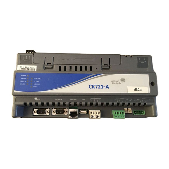
Network controller
Hide thumbs
Also See for CK721-A:
- Installation and operation manual (213 pages) ,
- Factory field upgrade (22 pages) ,
- Factory field installation (21 pages)

Subscribe to Our Youtube Channel
Related Manuals for Johnson Controls CK721-A


Summary of Contents for Johnson Controls CK721-A
- Page 1 CK721-A Network Controller Installation and Operation Manual April, 2012 24-10349-8 Revision B...
- Page 3 CK721-A Network Controller Installation and Operation Manual April, 2012 24-10349-8 Revision B Security Solutions (805) 522-5555 www.johnsoncontrols.com...
- Page 4 Copyright 2012 Johnson Controls, Inc. All Rights Reserved No part of this document may be reproduced without the prior permission of Johnson Controls, Inc.
- Page 5 Federal Communications Commissions Notice This equipment, CK721-A, has been tested and found to comply with the limits for a Class B digital device, pursuant to Part 15 of the FCC rules. These limits are designed to provide reasonable protection against harmful interference in a residential installation.
- Page 6 13. The Kone IP elevator interface has not been investigated by Underwriters Laboratories. 14. Do not connect equipment to an AC power source that is controlled by a switch. 15. For CK721-A, provided as part of an SPA, SPB, and SPC security control panel assembly, items 1 and 4 through 13 apply.
-
Page 7: Table Of Contents
Wiring CK721-A and Modules ....................... 2-11 CK721-A Cable Requirements....................2-11 Chain Module Wiring......................2-12 Cable Routing ........................2-12 Chassis Grounding........................ 2-13 24-10349-8 Rev. B This document contains confidential and proprietary information of Johnson Controls, Inc. © 2012 Johnson Controls, Inc. - Page 8 RS-485 Wiring ..........................3-38 S300-I16 Unsupervised Input Module ................... 3-41 S300-IO8 Unsupervised Input/Output Module ................3-43 S300-SIO8 Supervised Input/Output Module ................3-45 24-10349-8 Rev. B This document contains confidential and proprietary information of Johnson Controls, Inc. © 2012 Johnson Controls, Inc.
- Page 9 PIN Retry Alarm ........................4-38 Assisted Access ..........................4-38 ADA Relay..........................4-39 Panel Entry/Exit ..........................4-39 Badge Entry/Exit Options ...................... 4-39 24-10349-8 Rev. B This document contains confidential and proprietary information of Johnson Controls, Inc. © 2012 Johnson Controls, Inc.
- Page 10 Non “D-Type” Grounding Connections ....................C-3 Installations in the USA ........................C-3 Installations in Europe ........................C-4 Card Reader Unit Grounding ........................C-4 viii 24-10349-8 Rev. B This document contains confidential and proprietary information of Johnson Controls, Inc. © 2012 Johnson Controls, Inc.
- Page 11 Quick Guide to Using Keypad Readers ....................F-8 Appendix G: Configuring SSH and SFTP Clients PuTTY Client............................G-1 WinSCP Client ............................G-5 24-10349-8 Rev. B This document contains confidential and proprietary information of Johnson Controls, Inc. © 2012 Johnson Controls, Inc.
- Page 12 Table of Contents CK721-A Installation and Operation 24-10349-8 Rev. B This document contains confidential and proprietary information of Johnson Controls, Inc. © 2012 Johnson Controls, Inc.
- Page 13 Large Enclosure With Installed Components ....................2-10 One CK721-A Module Mounted in a Large Enclosure ..................2-10 One CK721-A Module and Two RDR2S Modules Mounted in a Large Enclosure .......... 2-10 Daisy Chain Module Wiring for S300-DIN-L ....................2-12 Small Enclosure With Installed Components ....................2-13 One CK721-A Module Mounted in a Small Enclosure ..................
- Page 14 Example of Grounding Shielded Cable at Only One End ..................C-4 Input/Output Contact Wiring ..........................D-3 CK705/CK720 Write DB to Flash Dialog Box ....................E-1 24-10349-8 Rev. B This document contains confidential and proprietary information of Johnson Controls, Inc. © 2012 Johnson Controls, Inc.
- Page 15 Required Settings - Panel Menu ........................4-10 Panel Screen, Page 1 ............................4-13 Panel Screen, Page 2 ............................4-15 Panel Screen, Page 3 ............................4-18 24-10349-8 Rev. B xiii This document contains confidential and proprietary information of Johnson Controls, Inc. © 2012 Johnson Controls, Inc.
- Page 16 CK721-A Using Legacy Addressing Mode ......................B-1 CK721-A Using Physical Addressing Mode .......................B-1 Input/Output Linking, S300-SIO8, SW1 position 4 set ON .................D-2 24-10349-8 Rev. B This document contains confidential and proprietary information of Johnson Controls, Inc. © 2012 Johnson Controls, Inc.
-
Page 17: Manual Conventions
Chapter I N T R O D U C T I O N This chapter provides a general description of the CK721-A panel and related equipment. The conventions used throughout this manual are also described. The manual is divided into the following chapters: Chapter 1: Introduction, defines the key terms and conventions used throughout the ... -
Page 18: Key Terms
Advanced Encryption Standard (AES) – Encryption standard adopted by the U.S. government in 2002; it supersedes DES. AES uses a symmetrical key algorithm. CK721-A System – This is a general term that refers to a combination of CK721-A terminals and expansion enclosures that communicate with the P2000 system. -
Page 19: Unpacking The Equipment
The indicator can be seen when the cabinet door is closed. External Device – This general term applies to any device that is wired to the CK721-A system, such as a reader or input device. A motion sensor is one type of input device. -
Page 20: General Description
All CK721-A panels are connected via a 10/100Base-T Ethernet network to the P2000 system. The CK721-A is intended to be mounted in an S300-DIN enclosure (large or small). Each model has a total capacity 200,000 cards and a 8000 off-line transaction base memory. -
Page 21: Enclosures
S300-DIN-RDR2S, or S300-DIN-RDR2SA) and for a battery back-up unit. S300-DIN-L A large enclosure containing DIN rails, a tamper switch and a power supply. It has room for up to three modules (CK721-A, RDR2S, RDR2S-A, or a combination thereof), and for a bat- tery back-up unit. S300-XL A large expansion enclosure containing a tamper switch, a power indicator light, and a power supply. -
Page 22: Modules
This module is also referred to as the SIO8. S300-SI8 Eight 4-state inputs. This module is also referred to as the SI8. 24-10349-8 Rev. B This document contains confidential and proprietary information of Johnson Controls, Inc. © 2012 Johnson Controls, Inc. -
Page 23: Additional Equipment
S300-DIN-PA1 Parts Accessory Kit. Contains a DC power harness, a lock, a tamper switch, and two spare connectors (3-position and 4-position). 24-10349-8 Rev. B This document contains confidential and proprietary information of Johnson Controls, Inc. © 2012 Johnson Controls, Inc. -
Page 24: Specifications (All Panels)
S300-BAT in S300-DIN-L: minimum one hour sus- tained operation at full load. S300-BAT-2.8AH in S300-DIN-S: minimum one and a half hours sustained operation at full load. 24-10349-8 Rev. B This document contains confidential and proprietary information of Johnson Controls, Inc. © 2012 Johnson Controls, Inc. -
Page 25: Ck721-A Panel Configuration
S300 modules as possible, and all S300 modules should be operating in physical addressing mode. The typical response time to an access request in an idle CK721-A with 64 terminals on 8 RDR8S modules is less than 500 ms. The typical response time to an access request in an idle CK721-A with 64 terminals on 32 RDR2SA modules is less than 1s. -
Page 26: System Configuration Example
10/100Base-T Networking Guidelines (specific to the CK721-A) As a network device, the CK721-A can be installed in a variety of configurations based on the needs of your sites. The CK721-A communicates with the P2000 server through one or more 10/100Base-T hubs. -
Page 27: Network Communication
two hubs, or the distance between a hub and a network device such as the CK721-A. Wiring from a CK721-A to a hub is straight through. Specifically: CAT-5, 8 conductor cable, RJ45 connectors. The following diagram illustrates the 4x5 rule. -
Page 28: Tcp/Ip
IP address. Each networked device on a TCP/IP, 10/100Base-T Ethernet, must be assigned a unique IP address. The CK721-A is no exception. In basic terms, network communication is accomplished through the transmission and receipt of packets. Packets contain a variable length of data, along with the IP address of the device to which the packet is addressed. -
Page 29: Communication Modes
This feature provides encrypted network communications between the CK721-A controller and the P2000 Server, using the Advanced Encryption Standard (AES256). The CK721-A Encryption is implemented using the Federal Information Processing Standards (FIPS) 140-2, validated (Certificate #1051), cryptographic module (version 1.2.3) from the Open Source Software Institute (http://www.oss-institute.org). -
Page 30: Ck721-A/P2000 Server Encrypted Communications
controller reboot. All controller functions are disabled during that time. For the CK721-A controller to come on-line with the P2000 Server, the encryption key values at the CK721-A controller and at the P2000 server must match, and the encryption must be enabled at both sides. - Page 31 CK721-A Installation and Operation Introduction When encryption is enabled, the following methods are supported for CK721-A controller login connections: Secure Shell Telnet Client (SSH) Secure FTP Client (SFTP). Serial Port (RS-232C, Port A). Serial communications between the CK721-A ...
- Page 32 Introduction CK721-A Installation and Operation 1-16 24-10349-8 Rev. B This document contains confidential and proprietary information of Johnson Controls, Inc. © 2012 Johnson Controls, Inc.
-
Page 33: 2: Ck721-A And S300-Din Enclosures
C K 7 2 1 - A A N D S 3 0 0 - D I N E N C L O S U R E S This chapter describes the equipment used with the CK721-A. CK721-A This section describes components of the CK721-A. Picture of the module is followed by a detailed description of the components. The major functional components of the CK721-A are: Embedded 32-bit processor ... -
Page 34: Leds On The Ck721-A
End-of-Line connector connector binary inputs switches RJ45 LEDs on the CK721-A There are nine LEDs on the CK721-A board. Their functions are shown in Table 2-1. Table 2-1: CK721-A LED Functions Function POWER ON steady when power is applied. FAULT OFF to indicate normal operation.ON indicates a general fault. -
Page 35: Binary Output
CK721-A and S300-DIN Enclosures Binary Output The CK721-A provides a relay output for connecting to an external alarm at Binary Out1. If the alarm relay is programmed for enabled, and the individual inputs are programmed to activate the relay, the relay can be activated when any input point in the system goes into alarm. -
Page 36: Lithium Battery
CK721-A Lithium Battery The CK721-A contains a lithium battery that is used for realtime clock backup. The lithium battery is shipped from the factory charged and operational. Lithium battery If there are no power outages, the battery should be changed every five years. If a power outage occurs, the battery life is approximately 30 days. -
Page 37: Input Power
9600 bps, even parity, 8 bit per character, and one stop bit Figure 2-1 and Figure 2-2 show shows the wiring between RS485B and the devices. 24-10349-8 Rev. B This document contains confidential and proprietary information of Johnson Controls, Inc. © 2012 Johnson Controls, Inc. -
Page 38: Binary Input
23.9 VDC or less. For wiring details see Figure 2-3. CK721-A: BINARY Power Supply: TROUBLE Figure 2-3: Wiring Between Binary Input 1 and Trouble Pin 24-10349-8 Rev. B This document contains confidential and proprietary information of Johnson Controls, Inc. © 2012 Johnson Controls, Inc. -
Page 39: Connecting The Network
Hub to CK721-A Wiring All network devices designed for 10/100Base-T networking use standard RJ45, 8 pin ports. Like other 10/100Base-T devices, the CK721-A RJ45 port is designed to connect to a hub using pins 1, 2, 3, and 6, wired straight through. -
Page 40: Rs232 Serial Null Modem Cable Wiring
Ring Indicator (In) RS232 Serial Null Modem Cable Wiring The null modem cable provides an RS232 serial connection from the CK721-A RS232C A port to the computer’s COM port. 24-10349-8 Rev. B This document contains confidential and proprietary information of Johnson Controls, Inc. -
Page 41: Large Enclosure (S300-Din-L)
Figure 2-5 gives you an overview of the large enclosure with all components installed. The modules shown here are RDR2S. 24-10349-8 Rev. B This document contains confidential and proprietary information of Johnson Controls, Inc. © 2012 Johnson Controls, Inc. -
Page 42: Large Enclosure With Installed Components
The figure below depicts the CK721-A module mounted alone. Figure 2-6: One CK721-A Module Mounted in a Large Enclosure The figure below depicts the CK721-A module mounted with the RDR2S modules. Figure 2-7: One CK721-A Module and Two RDR2S Modules Mounted in a Large Enclosure 2-10 24-10349-8 Rev. -
Page 43: Wiring Ck721-A And Modules
RJ45 crimp tool to be supplied by customer. 1. For KONE elevator wiring diagram see Figure 4-7 on page 4-47. 24-10349-8 Rev. B 2-11 This document contains confidential and proprietary information of Johnson Controls, Inc. © 2012 Johnson Controls, Inc. -
Page 44: Chain Module Wiring
Refer to Appendix C: Grounding and Connectors for details on the requirements. The grounding screws used are #6 x 1/4” self-tapping, and are provided in the hardware installation kit. 2-12 24-10349-8 Rev. B This document contains confidential and proprietary information of Johnson Controls, Inc. © 2012 Johnson Controls, Inc. -
Page 45: Chassis Grounding
The backplate contains a power supply and a DIN rail for mounting of one CK721-A or a S300-DIN module (RDR8S, I32O16, RDR2S-A, or RDR2S). The enclosure can also hold a backup battery unit composed of two 12V lead-acid batteries in one battery bracket. -
Page 46: Verifying Dc And Chassis Ground
Do not connect the DC power cable to the CK721-A until all wiring is complete. The following figure depicts one CK721-A module in a small enclosure. -
Page 47: Cable Routing
The CK721-A modules should be mounted on a DIN rail. DIN Rail Mounting To mount an CK721-A module on a DIN rail, align it with the rail and snap on. To remove a module, pull down the white clip located on the bottom of the module, then pull the bottom of the module out and lift it up. -
Page 48: Vdc Connector
For power wiring with either the large or small enclosure, use the cable assembly shown in Figure 2-12. To construct the power wiring, use 18AWG wires. When connecting multiple CK721-A controllers or S300-DIN modules, wire the modules in parallel following the “daisy chain” pattern as shown in Figure 2-13. For details on wiring multiple modules, refer to the documentation provided with the S300-DIN module. -
Page 49: Ground Wiring
0.11" holes located at the bottom of the plate with a #6 self-tapping screw. When connecting CK721-A to multiple S300-DIN modules, wire them in parallel following the “daisy chain” pattern as shown in Figure 2-13. For wiring details refer to the documentation provided with the S300-DIN module. - Page 50 CK721-A and S300-DIN Enclosures CK721-A Installation and Operation 2-18 24-10349-8 Rev. B This document contains confidential and proprietary information of Johnson Controls, Inc. © 2012 Johnson Controls, Inc.
-
Page 51: 3: S300 Expansion Enclosures
NCLOSURES The S300 expansion enclosures are used to host additional modules in the CK721-A system. They cannot, however, be used with the CK721-A controller itself, because they do not have the DIN rails necessary for its mounting. Installing the Expansion Enclosures Before beginning, take a moment to read the following important notes. -
Page 52: Tools Required
If a wrist strap is not available, touch any part of the metal CK721-A cabinet prior to handling components to discharge static electricity. It is advisable to avoid working on carpeted areas if possible. -
Page 53: S300-Xl (S300 Expansion Enclosure, Large)
(41 cm) 5.5 inches (14 cm) 21 inches (53 cm) Power Supply Power Lock Tamper Switch Indicator Light Figure 3-1: S300-L 24-10349-8 Rev. B This document contains confidential and proprietary information of Johnson Controls, Inc. © 2012 Johnson Controls, Inc. -
Page 54: S300-Xs (S300 Expansion Enclosure, Small)
9 inches (23 cm) Power Supply 13 inches (33 cm) Lock Power Indicator 5.5 inches (14 cm) Tamper Switch Figure 3-3: S300-XXS 24-10349-8 Rev. B This document contains confidential and proprietary information of Johnson Controls, Inc. © 2012 Johnson Controls, Inc. -
Page 55: Removing The Knockouts
Remove the knockouts using a hammer and a punch. Remove only the knockouts required for wiring. Knockouts Figure 3-4: S300 Expansion Enclosure Knockouts 24-10349-8 Rev. B This document contains confidential and proprietary information of Johnson Controls, Inc. © 2012 Johnson Controls, Inc. -
Page 56: Mounting The Enclosures
14.5 inches (36.8 cm) Large Panel 19.125 Expansion (48.5 cm) Enclosure Figure 3-5: Mounting the Panels: S300-XL 24-10349-8 Rev. B This document contains confidential and proprietary information of Johnson Controls, Inc. © 2012 Johnson Controls, Inc. -
Page 57: Installing The Power Supplies
This section describes the installation and wiring of S300 modules. The modules include input and output modules and reader modules. The wiring instructions are the same for modules in expansion enclosures. 24-10349-8 Rev. B This document contains confidential and proprietary information of Johnson Controls, Inc. © 2012 Johnson Controls, Inc. -
Page 58: First Level Module Locations In S300-Xl
S300-SI8 - Supervised Input module The maximum distance from a CK721-A to the last module connected to it is 4000 feet (1219 meters). To facilitate future expansion, modules should be installed sequentially as shown in Figure 3-8 through Figure 3-10. -
Page 59: First Level Module Locations In S300-Xs
2. Position the module over the standoffs and secure with the mounting screws. 3. Attach RS485 cable from the CK721-A to the module, or module to module. All four mounting screws must be used to ensure proper grounding. 24-10349-8 Rev. B This document contains confidential and proprietary information of Johnson Controls, Inc.... -
Page 60: Installing The Second Level (Stacked) Modules
Figure 3-13. Only use these locations, because room must be left inside the cabinet for the door to close with the backup battery installed. Figure 3-11: Stacked Module Locations in S300-XL 3-10 24-10349-8 Rev. B This document contains confidential and proprietary information of Johnson Controls, Inc. © 2012 Johnson Controls, Inc. -
Page 61: Stacked Module Locations In S300-Xs
CK721-A Installation and Operation S300 Expansion Enclosures Figure 3-12: Stacked module Locations in S300-XS Figure 3-13: Stacked Module Locations in S300-XXS 24-10349-8 Rev. B 3-11 This document contains confidential and proprietary information of Johnson Controls, Inc. © 2012 Johnson Controls, Inc. -
Page 62: Cabling
The cables should run in grounded conduit or at least two feet from AC power, fluorescent lights, or other high energy sources. 3-12 24-10349-8 Rev. B This document contains confidential and proprietary information of Johnson Controls, Inc. © 2012 Johnson Controls, Inc. -
Page 63: Cabling Between Enclosures
All cables must conform with National Electrical Code, NFPA 70,* and local electrical codes. Cabling should be made using good wiring practices and should be long enough to allow service loops at their terminations in the CK721-A enclosure. *For Canadian installations, refer to the Canadian Electric Code C22.1. -
Page 64: Cable Assembly For Enclosure To Enclosure Connection
Use terminals) listed 18 AWG, 3-conductor shielded cable. Figure 3-14: Cable Assembly for Enclosure to Enclosure Connection 3-14 24-10349-8 Rev. B This document contains confidential and proprietary information of Johnson Controls, Inc. © 2012 Johnson Controls, Inc. -
Page 65: Cable Assembly For Enclosure To Enclosure Connection - Details
CONDUCTIVE SCREWS TO MAINTAIN THE PROTECTION GROUND BOND. Figure 3-15: Cable Assembly for Enclosure to Enclosure Connection - Details Refer to Figure 3-17 for connector orientation. 24-10349-8 Rev. B 3-15 This document contains confidential and proprietary information of Johnson Controls, Inc. © 2012 Johnson Controls, Inc. -
Page 66: Equipment Grounding
Table 3-2: S300 Expansion Enclosure AC Power Specifications Parameter Specification 24 VAC 10% Line Voltage 50 or 60 Hz 1% Line Frequency 3-16 24-10349-8 Rev. B This document contains confidential and proprietary information of Johnson Controls, Inc. © 2012 Johnson Controls, Inc. -
Page 67: S300-Ps Power Supply
Do not connect a single transformer to multiple power supplies. LED1 LED2 LED3 AC OK Figure 3-16: Power Supply 24-10349-8 Rev. B 3-17 This document contains confidential and proprietary information of Johnson Controls, Inc. © 2012 Johnson Controls, Inc. - Page 68 AC power is restored. If none of the LEDs light when plugging in AC power, verify that AC power is active. 3-18 24-10349-8 Rev. B This document contains confidential and proprietary information of Johnson Controls, Inc. © 2012 Johnson Controls, Inc.
-
Page 69: S300 Enclosure Power Consumption
In some cases these numbers can be reduced when specific features of a module are not in use (for example, output and supervised inputs). 24-10349-8 Rev. B 3-19 This document contains confidential and proprietary information of Johnson Controls, Inc. © 2012 Johnson Controls, Inc. - Page 70 (16 Secure State) Worst Case 1.19 Typical (4 Alarms) Typical (8 Alarms) Typical (12 Alarms) 210 Typical (16 Alarms) 230 3-20 24-10349-8 Rev. B This document contains confidential and proprietary information of Johnson Controls, Inc. © 2012 Johnson Controls, Inc.
- Page 71 The working range for +5V should be between +5.20 to +4.85. If a voltage drop, between modules, is greater than 0.05VDC, the quality of the interconnect cables should be checked. 24-10349-8 Rev. B 3-21 This document contains confidential and proprietary information of Johnson Controls, Inc. © 2012 Johnson Controls, Inc.
-
Page 72: Applying Power To The S300 Expansion Enclosure
AC earth/safety ground. The S300 enclosure provides a conductive mounting system that must be field- connected to AC earth/safety ground 3-22 24-10349-8 Rev. B This document contains confidential and proprietary information of Johnson Controls, Inc. © 2012 Johnson Controls, Inc. -
Page 73: Legacy Reader Module
EGACY EADER ODULE The legacy reader module described in this section is RDR2. A single CK721-A can communicate with 24 legacy modules, but only up to 8 of them can be reader modules. Firmware Versions for Reader Modules Table 3-10: Legacy Reader Module Firmware Versions... -
Page 74: Connector Positions
RS-485 cables once the stacked modules are installed. Each module is shipped with an RS-485 cable. The first module connects the cable between J5 on the CK721-A and one of the RS-485 connectors listed in Table 3-11 depending on which module is installed. -
Page 75: S300-Rdr2 Module
+12 VDC reader power output at 150 milliamperes RX TX 5V 12V RDR2 RDR1 Figure 3-18: S300-RDR2 Module 24-10349-8 Rev. B 3-25 This document contains confidential and proprietary information of Johnson Controls, Inc. © 2012 Johnson Controls, Inc. - Page 76 Indicates when data is transmitted or received and the presence of 5 and 12 VDC, as labeled on page 3-25. S300-RDR2 Firmware 3-26 24-10349-8 Rev. B This document contains confidential and proprietary information of Johnson Controls, Inc. © 2012 Johnson Controls, Inc.
-
Page 77: Reader Module Address Settings
7 and 8 No two reader modules connected to the same CK721-A can have the same address. The address of the reader terminal pair is determined by SW1 switch settings on the reader module as shown in Table 3-13. -
Page 78: Wiring Readers
2 Reader Module J1, J2, J3 J4, J5, J6 To connect your readers, refer to Figure 3-20 through Figure 3-24. 3-28 24-10349-8 Rev. B This document contains confidential and proprietary information of Johnson Controls, Inc. © 2012 Johnson Controls, Inc. -
Page 79: Warm-Up Resistor Removal
2, Red Lamp reader 1, Green Lamp reader 2, Green Lamp Remove only the warming resistors that must be removed. 24-10349-8 Rev. B 3-29 This document contains confidential and proprietary information of Johnson Controls, Inc. © 2012 Johnson Controls, Inc. - Page 80 Col (J1-2) COL 2 Col (J1-3) COL 3 Col (J1-7) COL 4 Col (J1-8) Figure 3-20: Wiring Diagram, Cardkey Keypad Reader 3-30 24-10349-8 Rev. B This document contains confidential and proprietary information of Johnson Controls, Inc. © 2012 Johnson Controls, Inc.
-
Page 81: Wiring Diagram, Single Data Wire Cardkey Readers
COL 2 Col (J1-3) COL 3 Col (J1-7) COL 4 Col (J1-8) Figure 3-21: Wiring Diagram, Single Data Wire Cardkey Readers 24-10349-8 Rev. B 3-31 This document contains confidential and proprietary information of Johnson Controls, Inc. © 2012 Johnson Controls, Inc. -
Page 82: Wiring Diagram, Sensor Two Data Wire Wiegand Readers
SHNT +12V Sensor reader DATA “0” +5 Volts DATA “1” Figure 3-22: Wiring Diagram, Sensor Two Data Wire Wiegand Readers 3-32 24-10349-8 Rev. B This document contains confidential and proprietary information of Johnson Controls, Inc. © 2012 Johnson Controls, Inc. - Page 83 Proximity reader RED LED GRN LED DATA “0” +12 Volts DATA “1” Figure 3-23: Wiring Diagram, Two Data Wire Proximity Readers 24-10349-8 Rev. B 3-33 This document contains confidential and proprietary information of Johnson Controls, Inc. © 2012 Johnson Controls, Inc.
- Page 84 +12 or 24 GRN LED DATA “0” DATA “1” Figure 3-24: Wiring Diagram, Data Wire High Current or +24 Volt Proximity Readers 3-34 24-10349-8 Rev. B This document contains confidential and proprietary information of Johnson Controls, Inc. © 2012 Johnson Controls, Inc.
-
Page 85: Wiring For Door Controls
Lamp, Data, and Keypad Door Strike Power Supply reader Door Strike Figure 3-25: Example of a Typical CK721-A System 24-10349-8 Rev. B 3-35 This document contains confidential and proprietary information of Johnson Controls, Inc. © 2012 Johnson Controls, Inc. -
Page 86: Door Strike Wiring
Figure 3-26: Field Installed Metal Oxide Varistor A full line of varistor components is available from Harris Semiconductor (now Littelfuse Corp.). 3-36 24-10349-8 Rev. B This document contains confidential and proprietary information of Johnson Controls, Inc. © 2012 Johnson Controls, Inc. -
Page 87: Door Open Detector Wiring
(1N4148 or equivalent) across the relay coil. The diode cathode (banded end) is connected to pin 1 and the anode to pin 2. 24-10349-8 Rev. B 3-37 This document contains confidential and proprietary information of Johnson Controls, Inc. © 2012 Johnson Controls, Inc. -
Page 88: Legacy I/O Modules
A single CK721-A panel can communicate with 24 legacy modules: 8 reader modules and up to 16 I/O legacy modules. When planning what modules to include, consider the following: The I16 module has 16 input points. The CK721-A can support sixteen of these. -
Page 89: Connector Positions
RS-485 cables once the stacked modules are installed. Each module is shipped with an RS-485 cable. The first module connects the cable between J5 on the CK721-A and one of the RS-485 connectors listed in Table 3-17 depending on which module is installed. - Page 90 SIO8 or SI8 modules (supervised, 4-state alarms), you can only use terminal numbers 1 through 8. Terminal numbers 9 through 16 will be invalid. 3-40 24-10349-8 Rev. B This document contains confidential and proprietary information of Johnson Controls, Inc. © 2012 Johnson Controls, Inc.
-
Page 91: S300-I16 Unsupervised Input Module
16 red LED indicators which illuminate when each input is in alarm RX TX 5V 12V Figure 3-27: S300-I16 Module 24-10349-8 Rev. B 3-41 This document contains confidential and proprietary information of Johnson Controls, Inc. © 2012 Johnson Controls, Inc. - Page 92 Indicate when data is transmitted or received and the presence of 5 and 12 VDC, as labeled in the diagram above S300-I16 Firmware 3-42 24-10349-8 Rev. B This document contains confidential and proprietary information of Johnson Controls, Inc. © 2012 Johnson Controls, Inc.
-
Page 93: S300-Io8 Unsupervised Input/Output Module
Eight input LEDs which illuminate when each input is in alarm Eight output LEDs showing when each relay is energized RX TX 5V 12V Figure 3-28: S300-IO8 Module 24-10349-8 Rev. B 3-43 This document contains confidential and proprietary information of Johnson Controls, Inc. © 2012 Johnson Controls, Inc. - Page 94 Indicate when data is transmitted or received and the presence of 5 and 12 VDC, as labeled in Figure 3-28. S300-IO8 Firmware 3-44 24-10349-8 Rev. B This document contains confidential and proprietary information of Johnson Controls, Inc. © 2012 Johnson Controls, Inc.
-
Page 95: S300-Sio8 Supervised Input/Output Module
All other functions, including the eight output relays, are identical to the S300-IO8 module. RX TX 5V 12V Figure 3-29: S300-SIO8 Module 24-10349-8 Rev. B 3-45 This document contains confidential and proprietary information of Johnson Controls, Inc. © 2012 Johnson Controls, Inc. - Page 96 Indicates when data is transmitted or received, and the System presence of 5 and 12 VDC as labeled in Figure 3-30. LEDs S300-SIO8 Firmware 3-46 24-10349-8 Rev. B This document contains confidential and proprietary information of Johnson Controls, Inc. © 2012 Johnson Controls, Inc.
-
Page 97: S300-Si8 Supervised Alarm Input Module
Indicates when data is transmitted or received and the presence of 5 and 12 VDC, as shown in Figure 3-30. S300-SI8 Firmware 24-10349-8 Rev. B 3-47 This document contains confidential and proprietary information of Johnson Controls, Inc. © 2012 Johnson Controls, Inc. -
Page 98: Wiring Input/Output Devices
Alarm devices are wired to both two and four-state inputs in the same way. The difference between two and four-state alarms is the use of resistors on the four-state input at the alarm device end. Resistance is monitored by the CK721-A for open, short, alarm, and secure conditions. - Page 99 Figure 3-31: Wiring Input Points (two and four-state alarms) Ground Active Ground Active Figure 3-32: Circuit for two-state Inputs (normally closed) 24-10349-8 Rev. B 3-49 This document contains confidential and proprietary information of Johnson Controls, Inc. © 2012 Johnson Controls, Inc.
-
Page 100: Supervised Alarm Inputs
150 Ohms when closed and 300 Ohms when open. Resistance values below 40 Ohms cause a short condition and resistance above 500 Ohms causes an open condition. 3-50 24-10349-8 Rev. B This document contains confidential and proprietary information of Johnson Controls, Inc. © 2012 Johnson Controls, Inc. -
Page 101: Calibrating Four-State Alarm Inputs
(NO or NC). 24-10349-8 Rev. B 3-51 This document contains confidential and proprietary information of Johnson Controls, Inc. © 2012 Johnson Controls, Inc. -
Page 102: Output Relay Wiring
The LED is lit when the relay is energized. Normally Open Common Normally Closed S300 IO8 S300 SIO8 Figure 3-35: Configuration of Outputs 3-52 24-10349-8 Rev. B This document contains confidential and proprietary information of Johnson Controls, Inc. © 2012 Johnson Controls, Inc. -
Page 103: Output Wiring
(SIO8 Outputs and IO8 Outputs), the contacts should be protected by an external protection circuit. This protection circuit is application- specific as configured in the field. Johnson Controls would advise, at a minimum, a Metal Oxide Varistor (MOV) at the rated voltage relative to the application across the power source and power load interrupted by the mechanical relay. -
Page 104: Backup Battery
The backup battery is rated for a minimum of three hours on a fully loaded system in an expansion enclosure. 3-54 24-10349-8 Rev. B This document contains confidential and proprietary information of Johnson Controls, Inc. © 2012 Johnson Controls, Inc. -
Page 105: S300-Brk2 Battery Bracket Kit
3. Connect the battery cable from the battery terminals to J3 on the power supply. 24-10349-8 Rev. B 3-55 This document contains confidential and proprietary information of Johnson Controls, Inc. © 2012 Johnson Controls, Inc. -
Page 106: Battery Mounting For S300-Xl And S300-Xxs
Ensure the polarity connections are correct: Red wire to RED + and Black wire to BLK -. Bracket Battery Mounting Hardware Door +/- Connectors Figure 3-40: Battery Mounting for S300-XS 3-56 24-10349-8 Rev. B This document contains confidential and proprietary information of Johnson Controls, Inc. © 2012 Johnson Controls, Inc. -
Page 107: Battery Installation Location In S300-Xl
CK721-A Installation and Operation S300 Expansion Enclosures Figure 3-41: Battery Installation Location in S300-XL Figure 3-42: Battery Installation Location in S300-XS 24-10349-8 Rev. B 3-57 This document contains confidential and proprietary information of Johnson Controls, Inc. © 2012 Johnson Controls, Inc. -
Page 108: Battery Installation Location In S300-Xxs
S300 Expansion Enclosures CK721-A Installation and Operation Figure 3-43: Battery Installation Location in S300-XXS 3-58 24-10349-8 Rev. B This document contains confidential and proprietary information of Johnson Controls, Inc. © 2012 Johnson Controls, Inc. -
Page 109: Important Notes
CK721-A for operation. The user interface gives you direct access to most CK721-A operating commands and parameters from a laptop or other remote PC before it is connected to the P2000 system. These are useful when commissioning or troubleshooting the system. -
Page 110: Notes On Encryption
Do not attempt modifications to the controller database during controller database download operations. The CK721-A controllers have a C and a factory default host IP address. They allow the configuration of the CK721-A controller operational parameters via an Ethernet cross-over cable connected to the Ethernet port. -
Page 111: Communicating With The User Interface
CK721-A Installation and Operation CK721-A User Interface The CK721-A user interface can be used for troubleshooting purposes during normal operation. For identification purposes, the controller’s IP address and netmask must match the IP address and netmask in the P2000. Communicating with the User Interface... -
Page 112: Navigating Through The User Interface
5. Type your password when prompted. (The default password is master.) Press <Enter>. You have three chances to login to the CK721-A panel. After three attempts, the CK721-A disables login for about five minutes, after which time you may try again. (Both login and password are case-sensitive.) 7. - Page 113 4-72) will initiate calibration of selected inputs using the resistor connected across CAL terminals. This command is used with the S300-DIN modules. 24-10349-8 Rev. B This document contains confidential and proprietary information of Johnson Controls, Inc. © 2012 Johnson Controls, Inc.
-
Page 114: Write Flash
MPORTANT Write to flash commands must be issued after: Adding or deleting non-legacy input or output point(s) to the CK721-A database configuration. Adding or deleting a non-legacy terminal to the CK721-A database configuration. -
Page 115: Clearing The Flash Memory
Flash Memory. You can now download information from the P2000. Router Configuration The default CK721-A Panel Routing Information Protocol (RIP) is dynamic, that is, it regularly listens for RIP from the network. If RIP is disabled, manual route information can be added using this screen. -
Page 116: Notes On Adding Ip Addresses In Route Configuration Screen
- Verify that you can ping the gateway - Verify that you can ping the P2000 server - Check the CK721-A routing table using the command netstat -r - Use the command traceroute <host ip address> to verify route to the P2000 server 24-10349-8 Rev. -
Page 117: Ck721-A Static Route Examples
Figure 4-2: Static Route Examples Log Out After configuring or viewing system parameters, always log out, and then remove the serial cable. To log out from the CK721-A user interface, select Log Out, and press <Enter>. Rebooting the Panel Reboot the CK720 from the Main menu option Reboot System, or power cycle the panel. -
Page 118: Panel Menu
ASIC ANEL ONFIGURATION Panel Menu It is necessary to perform the following steps at every CK721-A controller in your system that communicates with the following server: P2000 server (version 3.8 build 57 with SP2, or later) These steps set the IP address and netmask, the preferred primary comm path, and the network polling of the CK721-A, which are required for communication with the above servers. -
Page 119: Panel
41012 (default value) 7. If you are using encryption, enter an encryption key value unique to this CK721-A controller and matching the value defined at the P2000 server. The value must be other than 0. After entering the key, enable the encryption. -
Page 120: Direct Programming Of The Ck721-A
But for testing the installation of the field controllers and related hardware, the user interface is a valuable tool. The remainder of this chapter describes all of the features available in the CK721-A user interface. For a more in-depth description of the features, refer to the P2000 Software User Manual. -
Page 121: Panel Screen Description
CK721-A Installation and Operation CK721-A User Interface Panel Screen Description The Panel screen is used when the CK721-A panel is configured for the P2000 server. Panel Screen - Page 1 Table 4-3: Panel Screen, Page 1 Field Type Description Panel Name User Def. - Page 122 19,200 baud. For information on firmware version required for High Speed RS485, see page 3-38. 4-14 24-10349-8 Rev. B This document contains confidential and proprietary information of Johnson Controls, Inc. © 2012 Johnson Controls, Inc.
-
Page 123: Panel Screen
“percent full” value. In order to work, this option must be enabled in the previous field. Percentage range: 0 - 99 24-10349-8 Rev. B 4-15 This document contains confidential and proprietary information of Johnson Controls, Inc. © 2012 Johnson Controls, Inc. - Page 124 User Def. For algorithmic PIN codes select 4 or 5 digits. For custom PIN coders select 4 to 9 digits. 4-16 24-10349-8 Rev. B This document contains confidential and proprietary information of Johnson Controls, Inc. © 2012 Johnson Controls, Inc.
-
Page 125: Panel Screen
Linking settings) require a write of the database to flash before the updated Panel Output Relay settings take effect. Panel Screen - Page 3 24-10349-8 Rev. B 4-17 This document contains confidential and proprietary information of Johnson Controls, Inc. © 2012 Johnson Controls, Inc. - Page 126 A database backup period of 0 hours disables automatic database backups to flash memory. Custom User Def. Selects and enables custom features. Configuration Number 4-18 24-10349-8 Rev. B This document contains confidential and proprietary information of Johnson Controls, Inc. © 2012 Johnson Controls, Inc.
-
Page 127: Terminal
Terminal screens are used to configure the individual readers, and input/output terminals connected to the CK721-A. You can edit an existing terminal or add a new terminal to the system. When you select the Terminal option and a new terminal number, the system automatically assumes you are adding a new record. -
Page 128: Terminal Screen
CK721-A. Disabled (D) means the terminal can be defined, but will not be polled. 4-20 24-10349-8 Rev. B This document contains confidential and proprietary information of Johnson Controls, Inc. © 2012 Johnson Controls, Inc. - Page 129 Time to set the number of minutes a card remains invalid at Anti-Passback readers after the card has been granted access at an Anti-Passback reader. 24-10349-8 Rev. B 4-21 This document contains confidential and proprietary information of Johnson Controls, Inc. © 2012 Johnson Controls, Inc.
- Page 130 A timezone that, when active, puts the terminal into unrestricted access. (Timezones are numbered 1 to 64; 0 means no timezone is assigned.) 4-22 24-10349-8 Rev. B This document contains confidential and proprietary information of Johnson Controls, Inc. © 2012 Johnson Controls, Inc.
-
Page 131: Terminal Screen
For the RDR2S-A module the value range is 1 to 2. Note: Any changes to this field require a controller Write-To-Flash operation. 24-10349-8 Rev. B 4-23 This document contains confidential and proprietary information of Johnson Controls, Inc. © 2012 Johnson Controls, Inc. -
Page 132: Terminal Screen
Terminal Screen - Page 3 Page 3 of the Terminal screen is shown, followed by Table 4-8, which contains a description of each item. 4-24 24-10349-8 Rev. B This document contains confidential and proprietary information of Johnson Controls, Inc. © 2012 Johnson Controls, Inc. - Page 133 Reverse Card Bit Order must be enabled as well. (This corresponds to “Reverse Swipe duress” in the Terminal window of the P2000 software.) 24-10349-8 Rev. B 4-25 This document contains confidential and proprietary information of Johnson Controls, Inc. © 2012 Johnson Controls, Inc.
- Page 134 Enable event, followed by keypad code. Disable event, followed by keypad code. Clear the keypad buffer. See Appendix F for details. 4-26 24-10349-8 Rev. B This document contains confidential and proprietary information of Johnson Controls, Inc. © 2012 Johnson Controls, Inc.
- Page 135 0 turns the feature off. For security reasons, this feature should only be used together with the Timed Shunt option. 24-10349-8 Rev. B 4-27 This document contains confidential and proprietary information of Johnson Controls, Inc. © 2012 Johnson Controls, Inc.
- Page 136 This option requires the use of the RDR2 module, firmware version PS-201E or later, or an S300-DIN module. See the “Assisted Access Timing Diagram” on page 4-39. 4-28 24-10349-8 Rev. B This document contains confidential and proprietary information of Johnson Controls, Inc. © 2012 Johnson Controls, Inc.
- Page 137 Note: Requires an S300-DIN module (RDR2S firmware must be revision Q or higher). BQT LCD Reader Toggle Not supported in CK721-A version 3.0. 24-10349-8 Rev. B 4-29 This document contains confidential and proprietary information of Johnson Controls, Inc. © 2012 Johnson Controls, Inc.
-
Page 138: Terminal Screen
Page 4 of the Terminal screen is shown followed by Table 4-9, which contains a description of each item. Page 4 allows you to define facility codes. 4-30 24-10349-8 Rev. B This document contains confidential and proprietary information of Johnson Controls, Inc. © 2012 Johnson Controls, Inc. -
Page 139: Terminal Screen
24-10349-8 Rev. B 4-31 This document contains confidential and proprietary information of Johnson Controls, Inc. © 2012 Johnson Controls, Inc. - Page 140 Select (Y) to allow this custom format. Meanings of the custom formats 1 to 8 are assigned at the host. 4-32 24-10349-8 Rev. B This document contains confidential and proprietary information of Johnson Controls, Inc. © 2012 Johnson Controls, Inc.
-
Page 141: Offline Access Card Type Requirements
I/O points. The following RDR8S reader terminal output points can be re-assigned: Red LED Green LED Reader Strike 24-10349-8 Rev. B 4-33 This document contains confidential and proprietary information of Johnson Controls, Inc. © 2012 Johnson Controls, Inc. - Page 142 Input 1 Reader REX Input 2 A write to flash must be performed after completion of input point/output point disassociation configuration. 4-34 24-10349-8 Rev. B This document contains confidential and proprietary information of Johnson Controls, Inc. © 2012 Johnson Controls, Inc.
-
Page 143: Rdr2S-A Input Point And Output Point Disassociation
Reader Input Point Terminal Input Point Number Reader Door Contact Input 1 Reader REX Input 2 24-10349-8 Rev. B 4-35 This document contains confidential and proprietary information of Johnson Controls, Inc. © 2012 Johnson Controls, Inc. -
Page 144: Configuring Pin Codes
PIN in “PIN + Card ID” mode. 4-36 24-10349-8 Rev. B This document contains confidential and proprietary information of Johnson Controls, Inc. © 2012 Johnson Controls, Inc. -
Page 145: Pin
2. The PIN plus 1 Duress option is not enabled (see page 4-26). 3. The cardholder is required to enter a PIN at the terminal. 24-10349-8 Rev. B 4-37 This document contains confidential and proprietary information of Johnson Controls, Inc. © 2012 Johnson Controls, Inc. -
Page 146: Pin Plus 1 Duress
The access time of elevators is not affected by the Assisted Access feature. This feature satisfies the requirements for assisted access according to ADA (Americans with Disabilities Act). 4-38 24-10349-8 Rev. B This document contains confidential and proprietary information of Johnson Controls, Inc. © 2012 Johnson Controls, Inc. -
Page 147: Ada Relay
Time when badge is presented Figure 4-3: Assisted Access Timing Diagram Panel Entry/Exit Badge Entry/Exit Options The P2000 and CK721-A controllers support the following Badge Exit/Exit Enforcement and Synchronization modes: Global Badge Entry/Exit Status Synchronization Controller Badge Local Entry/Exit Enforcement ... - Page 148 Badge entry/exit status enforcement to a specific CK721-A controller and a maximum of 64 readers (32 pairs of In/Out readers). Therefore, a cardholder badge swiped on a reader terminal connected to one CK721-A controller would not have their entry/exit privileges synchronized on a reader terminal connected to different CK721-A controller.
-
Page 149: Elevator Access Control
An elevator cab must be equipped with one reader, and one output point needs to be assigned to every floor button in the cab that needs to be enabled by the security 24-10349-8 Rev. B 4-41 This document contains confidential and proprietary information of Johnson Controls, Inc. © 2012 Johnson Controls, Inc. -
Page 150: D620-Ecg Low Level Interface
If the floor call request is within the privileges associated with the badge, a momentary grant is issued by pulsing (activating/deactivating) the associated 4-42 24-10349-8 Rev. B This document contains confidential and proprietary information of Johnson Controls, Inc. © 2012 Johnson Controls, Inc. -
Page 151: Kone Hli/Kone Elink High Level Interface
The rest of this integration is identical to the low level elevator interface. 24-10349-8 Rev. B 4-43 This document contains confidential and proprietary information of Johnson Controls, Inc. © 2012 Johnson Controls, Inc. -
Page 152: Kone Ip High Level Interface
(you must select the Floor Tracking function). Each CK721-A panel can connect to multiple KONE IP group controllers, each controller with up to 8 elevators, each elevator serving up to 128 floors. To define a KONE IP elevator, you must first select the KONE IP protocol type in the Panel Elevator tab. -
Page 153: Kone Kic Controller With Multiple Elevator Groups
One KONE KIC Controller for All Elevator Groups In this scenario, all elevator groups use the same TCP port number and are connected to a single KONE KIC controller and a single CK721-A controller. KONE KIC Elevator Group 1... -
Page 154: And Multiple Ck721-A Controllers
TCP Port 1 IP Address 3 KONE IP Controller 4 (Backup) IP Address 4 Figure 4-6: Primary and Backup KONE IP Controllers 4-46 24-10349-8 Rev. B This document contains confidential and proprietary information of Johnson Controls, Inc. © 2012 Johnson Controls, Inc. -
Page 155: Otis E.m.s. - Security / B.m.s. Protocol High Level Interface
8 elevators. It interfaces to the Building Management System (BMS) through an RS422 interface. As the current CK721-A controller supports up to 16 elevator readers, multiple CK721-A may need to be connected to control access to all elevators managed by the EMS. - Page 156 Panel Configuration Panel Name Each CK721-A that takes part in the OTIS integration must follow a certain naming pattern. Enter each character of the CK721-A panel name as described in the tables below. Only characters 2, 3, and 4 must be entered as specified. Characters 5, 6, 7, and 8 may be non numeric if default values are to be used.
- Page 157 7th character 8th character: Master & Slave. This character defines the priority of the OTIS integration within a CK721-A controller. This setting should not be changed unless after consultation with Technical Support. Any invalid character uses the default priority of 19.
-
Page 158: Otis Compass High Level Interface
CK721-A then re-secures the floors after the configured elevator access time has elapsed, or when a new access request is processed that de-secures different floors. If the Timed Button flag is unchecked, the CK721-A re-secures the elevator as soon as it receives a reported landing number. - Page 159 (called a Destination Entry Computer or DEC) can be controlled by a reader connected to a CK721-A panel, if configured to do so. The OTIS system allows operation of the DECs in 4 different modes that define the availability of floors and the order in which floors and badges are presented to the system.
-
Page 160: Basic Definitions
Inputs (low level interface only) – Each elevator cab’s floor buttons may be wired to an input to allow the CK721-A to create floor tracking messages. A pressed button needs to close the input, a button that is not pressed needs leave the input open. The CK721-A elevator interface does not support normally closed buttons. -
Page 161: Performance Considerations
Performance Considerations The more readers and input/output terminals are installed at a single CK721-A, the longer the system response time gets. Also, care has to be taken not to exceed the power supplies’ capabilities when all output relays are energized at once. The theoretical limit per CK721-A is set to 16 elevators with 128 elevator buttons combined. -
Page 162: Elevator Or Cabinet Terminal
1 = high level interface (RS232) The following high level interfaces are supported: KONE PLC-HLI/KONE ELINK, OTIS BMS, OTIS COMPASS, and KONE IP. 4-54 24-10349-8 Rev. B This document contains confidential and proprietary information of Johnson Controls, Inc. © 2012 Johnson Controls, Inc. - Page 163 Floor/Door Tracking field is set to (Y). For a comprehensive table on setting flags for floor tracking messages, see page 4-56. 24-10349-8 Rev. B 4-55 This document contains confidential and proprietary information of Johnson Controls, Inc. © 2012 Johnson Controls, Inc.
- Page 164 Closing Opening Do not generate floor tracking messages. Input point wired to “normally open.” Input point wired to “normally closed.” 4-56 24-10349-8 Rev. B This document contains confidential and proprietary information of Johnson Controls, Inc. © 2012 Johnson Controls, Inc.
-
Page 165: Elevator Or Cabinet Terminal Screen
If an output point is assigned, it is identified by terminal number and point number. 24-10349-8 Rev. B 4-57 This document contains confidential and proprietary information of Johnson Controls, Inc. © 2012 Johnson Controls, Inc. -
Page 166: Output
After selecting a terminal, select an output point number. If the output you select already exists, the system places you into edit mode. If the output record does not exist, the CK721-A assumes you want to create a new record. Any output records you have defined will appear listed here. -
Page 167: Output Screen
Values are between 0 and 255 seconds. If the active state is set as timed, this value represents the duration for which the point will be set. 24-10349-8 Rev. B 4-59 This document contains confidential and proprietary information of Johnson Controls, Inc. © 2012 Johnson Controls, Inc. -
Page 168: Holiday
If so, the appropriate time zone is substituted. To define holidays, select Holiday from the CK721-A Main menu. You will be prompted for a holiday number. If the record exists, it can be edited. If the holiday number does not already exist, it is considered a new record. -
Page 169: Access Group
(s). To enable or disable particular reader terminals in an Access Group, select Access Group from the CK721-A Main menu. You can add an access group number as 1 or greater, or select a previously defined group to edit. -
Page 170: Elevator Access Group
Select (Y) to enable a terminal for this access group. Select (N) to disable a terminal for this access group. 4-62 24-10349-8 Rev. B This document contains confidential and proprietary information of Johnson Controls, Inc. © 2012 Johnson Controls, Inc. -
Page 171: Control Door
Control Door Door Control allows you to manually lock or unlock a door immediately or for a specified period of time. Select Control Door from the CK721-A Main menu. 24-10349-8 Rev. B 4-63 This document contains confidential and proprietary information of Johnson Controls, Inc.... -
Page 172: Panel Soft Alarm
Soft Alarm points are pre-programmed in the system. Although you do have access to these points from this screen, they should not be changed. Reporting problems will occur. 4-64 24-10349-8 Rev. B This document contains confidential and proprietary information of Johnson Controls, Inc. © 2012 Johnson Controls, Inc. -
Page 173: Panel Soft Alarm
Panel Soft Alarm User Def. The actual terminal number associated with the Address (1-16) soft alarms (for panel soft alarms). 24-10349-8 Rev. B 4-65 This document contains confidential and proprietary information of Johnson Controls, Inc. © 2012 Johnson Controls, Inc. -
Page 174: Password Change
CK721-A User Interface CK721-A Installation and Operation Password Change Use this option to change the login password for the CK721-A. Select Password Change from the CK721-A Main menu. Table 4-21: Password Change, 1 Page Only Field Type Description Enter New Password User Def. -
Page 175: Badge
CK721-A User Interface Type the system password and press <Enter>; the CK721-A will reboot. If you are connected to the CK721-A panel via the serial port, the boot up messages will be displayed. The reboot process is complete when the Login prompt appears. - Page 176 To delete a batch of badges previously created, specify a Start Badge and an End Badge value and then press <Delete>. 4-68 24-10349-8 Rev. B This document contains confidential and proprietary information of Johnson Controls, Inc. © 2012 Johnson Controls, Inc.
-
Page 177: Badge Screen
(C). See “Assisted Access” on page 4-38 for details. This feature requires the Assisted Access feature to be set to (F) at the terminal screen. 24-10349-8 Rev. B 4-69 This document contains confidential and proprietary information of Johnson Controls, Inc. © 2012 Johnson Controls, Inc. -
Page 178: Badge Screen
A single badge can be assigned up to 32 time zones (for time zones 17-32 see “Badge Parameters Screen - Page 3”). 4-70 24-10349-8 Rev. B This document contains confidential and proprietary information of Johnson Controls, Inc. © 2012 Johnson Controls, Inc. -
Page 179: Input
Reader only terminal, you can program a soft alarm using its assigned number. All other numbers will be invalid. To begin, select Input from the CK721-A Main menu, and then select a previously defined terminal from the displayed list. 24-10349-8 Rev. B 4-71 This document contains confidential and proprietary information of Johnson Controls, Inc.... - Page 180 If the point has not been defined, it will be a new record. 4-72 24-10349-8 Rev. B This document contains confidential and proprietary information of Johnson Controls, Inc. © 2012 Johnson Controls, Inc.
-
Page 181: Input Screen
(includes Output Latching and Alarm Relay Linking settings) require a write of the database to flash before the updated Panel Output Relay settings take effect. 24-10349-8 Rev. B 4-73 This document contains confidential and proprietary information of Johnson Controls, Inc. © 2012 Johnson Controls, Inc. - Page 182 Each individual input point can be assigned up to three input groups (0 indicates the point is not assigned to a group). 4-74 24-10349-8 Rev. B This document contains confidential and proprietary information of Johnson Controls, Inc. © 2012 Johnson Controls, Inc.
-
Page 183: Time Zone
Figure 4-8. To define or edit time zones, select Time Zone from the CK721-A Main menu. If records have been previously defined, they will be displayed. If you enter a time zone number not previously created, the system will add it as a new record. -
Page 184: Card Events
If the server performs the access transaction processing (in central or shared mode), the card event will not occur. 4-76 24-10349-8 Rev. B This document contains confidential and proprietary information of Johnson Controls, Inc. © 2012 Johnson Controls, Inc. - Page 185 To configure a new event or edit an existing one, select Card Event from the CK721-A Main menu. Next, select a previously saved event or type in a new event number to create a new card event record.
-
Page 186: Card Event Screen
If a door is enabled (Y), the event can be initiated at that location. You can enable any or all doors for a specific event. 4-78 24-10349-8 Rev. B This document contains confidential and proprietary information of Johnson Controls, Inc. © 2012 Johnson Controls, Inc. -
Page 187: Card Event Screen
24-10349-8 Rev. B 4-79 This document contains confidential and proprietary information of Johnson Controls, Inc. © 2012 Johnson Controls, Inc. - Page 188 4-80 24-10349-8 Rev. B This document contains confidential and proprietary information of Johnson Controls, Inc. © 2012 Johnson Controls, Inc.
-
Page 189: System Information
CK721-A User Interface System Information This screen provides information regarding the CK721-A. This includes items such as reader status, IP addresses, MAC number, and current time zone status. To access this information, select System Information from the CK721-A Main menu. - Page 190 Total number of stored history transactions in the CK721-A database. System Information Screen - Page 2 (Terminal and Security Level Status) 4-82 24-10349-8 Rev. B This document contains confidential and proprietary information of Johnson Controls, Inc. © 2012 Johnson Controls, Inc.
-
Page 191: System Information Screen
Time Zone Status 64 time zones can be defined. Status of each is shown as E(nabled), D(isabled), or (--) undefined. 24-10349-8 Rev. B 4-83 This document contains confidential and proprietary information of Johnson Controls, Inc. © 2012 Johnson Controls, Inc. -
Page 192: Control Output
Every output point, no matter which option was selected for it, can be commanded with 5 different active states. See Table 4-34 to determine the effect of the commands on each selected state. 4-84 24-10349-8 Rev. B This document contains confidential and proprietary information of Johnson Controls, Inc. © 2012 Johnson Controls, Inc. -
Page 193: Change Date
Change Date To set the CK721-A realtime clock, select Change Date from the CK721-A Main menu. The following screen is displayed. Enter the date in month/day/year format as shown above. Enter the time in 24-hour format as shown above. - Page 194 CK721-A User Interface CK721-A Installation and Operation 4-86 24-10349-8 Rev. B This document contains confidential and proprietary information of Johnson Controls, Inc. © 2012 Johnson Controls, Inc.
-
Page 195: Routine Maintenance
Cable length or type not as specified. Page 2-11, Table 3-1, and Figure 3-19. Backup battery not replaced correctly. This chapter. 24-10349-8 Rev. B This document contains confidential and proprietary information of Johnson Controls, Inc. © 2012 Johnson Controls, Inc. -
Page 196: Testing Procedure
Check for proper operation of the CK721-A as follows: 1. Verify POWER LED on the CK721-A. 2. Verify that the FAULT LED on the CK721-A is not on. 3. Verify the RS485B LED is flashing to show activity on the bus. -
Page 197: Field Servicing
CK721-A Installation and Operation Maintenance IELD ERVICING Troubleshoot the CK721-A by substituting the suspected defective panel with a new component. All replaceable parts are available from Johnson Controls, Inc. Consult your Customer Success Center representative at (800) 482-2778 for domestic orders or for instructions on how to obtain replaceable parts. - Page 198 Defective reader terminal Holiday time zones not fol- Improperly programmed Holiday time zones or lowed Holiday dates. 24-10349-8 Rev. B This document contains confidential and proprietary information of Johnson Controls, Inc. © 2012 Johnson Controls, Inc.
-
Page 199: Appendix A: Expanded Address S300 Bus
- OTIS E.M.S. - Security / B.M.S. Protocol High Level Interface - OTIS Compass High Level Interface The Expanded Address S300 Bus allows a CK721-A version 3.0 controller to communicate with up to 32 modules on the RS485 bus. 24-10349-8 Rev. B This document contains confidential and proprietary information of Johnson Controls, Inc.... - Page 200 Number (Physical Index, Number, Device Type Address), Value Range 1-8 Value Range 1-64 Value Range 0-31 RDR2S-A RDR2S-A RDR2S-A RDR8S RDR8S LEGACY 24-10349-8 Rev. B This document contains confidential and proprietary information of Johnson Controls, Inc. © 2012 Johnson Controls, Inc.
- Page 201 Average response time in ms 1258 1744 Table B-2: CK721-A Using Physical Addressing Mode Number of modules with I/O enabled Average response time in ms 24-10349-8 Rev. B This document contains confidential and proprietary information of Johnson Controls, Inc. © 2012 Johnson Controls, Inc.
-
Page 202: Appendix B: Performance Analysis
1800 1600 1400 1200 1000 Number of modules Legacy addressing mode Physical addressing mode Figure B-1: CK721-A Access Time Performance Graph 24-10349-8 Rev. B This document contains confidential and proprietary information of Johnson Controls, Inc. © 2012 Johnson Controls, Inc. -
Page 203: Cable Grounding
All internal ground (earth) bonding straps must be left intact after installation. 24-10349-8 Rev. B This document contains confidential and proprietary information of Johnson Controls, Inc. © 2012 Johnson Controls, Inc. -
Page 204: D-Type" Connectors
Do not remove the drain wire from the shield. MPORTANT Do not connect the shield to connector pin 1 in any way. 24-10349-8 Rev. B This document contains confidential and proprietary information of Johnson Controls, Inc. © 2012 Johnson Controls, Inc. -
Page 205: Non "D-Type" Grounding Connections
Short wire is UNIT2 connected from shield to PCBA enclosure of unit 2 Figure C-2: Example of Grounding Shielded Cable at Both Ends 24-10349-8 Rev. B This document contains confidential and proprietary information of Johnson Controls, Inc. © 2012 Johnson Controls, Inc. -
Page 206: Installations In Europe
AC or DC voltages and transients. 24-10349-8 Rev. B This document contains confidential and proprietary information of Johnson Controls, Inc. © 2012 Johnson Controls, Inc. -
Page 207: Purpose Of Supervised Inputs
Specifically, the relays will no longer respond to output control and output control status messages from the CK721-A. The modified outputs will always be reported as reset. Inputs five and eight will only report the two trouble conditions: circuit open and ... - Page 208 GND input on the reader module. Open or short circuit conditions at the four-state inputs will be reported to the CK721-A by the SIO8 module without affecting the reader module’s inputs. As a result, the relay contacts will appear to the RDR2 module exactly as if two-state contacts were being used.
- Page 209 CK721-A Installation and Operation Door Open/Aux Access Supervision NO C NC NO C NC NO C NC Figure D-1: Input/Output Contact Wiring 24-10349-8 Rev. B This document contains confidential and proprietary information of Johnson Controls, Inc. © 2012 Johnson Controls, Inc.
- Page 210 Door Open/Aux Access Supervision CK721-A Installation and Operation 24-10349-8 Rev. B This document contains confidential and proprietary information of Johnson Controls, Inc. © 2012 Johnson Controls, Inc.
- Page 211 This appendix explains the procedure for performing a Database Flash Backup. It will enable you to backup CK721-A data to the CPU’s on board flash memory. Consequently, if the panel does not have a backup battery (UPS) or the data is not backed up to the on board flash memory, all database information will be lost after a power cycle.
-
Page 212: Appendix E: Database Flash Backup From The Host
Database Flash Backup from the Host CK721-A Installation and Operation 24-10349-8 Rev. B This document contains confidential and proprietary information of Johnson Controls, Inc. © 2012 Johnson Controls, Inc. -
Page 213: Invoking Access Requests From A Keypad
2. The terminal’s Card ID flag must be set. 3. Make sure the terminal’s PIN Only flag is not set. 24-10349-8 Rev. B This document contains confidential and proprietary information of Johnson Controls, Inc. © 2012 Johnson Controls, Inc. -
Page 214: Invoking Air Crew Access Requests From A Keypad
To invoke Timed Override with Badge: 1. The terminal’s Cardholder Override flag must be set. 2. The badge’s Override flag must be set. 24-10349-8 Rev. B This document contains confidential and proprietary information of Johnson Controls, Inc. © 2012 Johnson Controls, Inc. - Page 215 4. The terminal’s Card ID flag must be set. 5. Make sure the terminal’s PIN Only flag is not set. 24-10349-8 Rev. B This document contains confidential and proprietary information of Johnson Controls, Inc. © 2012 Johnson Controls, Inc.
- Page 216 With the Star Feature, enter PIN, press the star (*) key followed by number 0, enter the number of minutes, and present the badge. 24-10349-8 Rev. B This document contains confidential and proprietary information of Johnson Controls, Inc. © 2012 Johnson Controls, Inc.
-
Page 217: Invoking Panel Card Events From A Keypad
With the Star Feature, press the star (*) key followed by number 1, enter the keypad code, and present the badge. 24-10349-8 Rev. B This document contains confidential and proprietary information of Johnson Controls, Inc. © 2012 Johnson Controls, Inc. - Page 218 With the Star Feature, enter the Card ID number, press the star (*) key followed by number 1, enter the keypad code, and press the # key. 24-10349-8 Rev. B This document contains confidential and proprietary information of Johnson Controls, Inc. © 2012 Johnson Controls, Inc.
- Page 219 With the Star Feature, enter PIN, press the star (*) key followed by number 4, enter the keypad code, and present the badge. 24-10349-8 Rev. B This document contains confidential and proprietary information of Johnson Controls, Inc. © 2012 Johnson Controls, Inc.
-
Page 220: Quick Guide To Using Keypad Readers
Use the terminal’s Star Feature if you want to invoke Panel Card Events on a keypad that does not have the keys A and D. 24-10349-8 Rev. B This document contains confidential and proprietary information of Johnson Controls, Inc. © 2012 Johnson Controls, Inc. - Page 221 Invoking Air Crew Access Requests from a Keypad Air Crew PIN To request access without Star Feature: Air Crew PIN To request access with Star Feature: 24-10349-8 Rev. B This document contains confidential and proprietary information of Johnson Controls, Inc. © 2012 Johnson Controls, Inc.
- Page 222 The badge can be presented at any time before the # key is pressed, that is, before, during or after the PIN and the Timed Override sequence are entered. F-10 24-10349-8 Rev. B This document contains confidential and proprietary information of Johnson Controls, Inc. © 2012 Johnson Controls, Inc.
- Page 223 The badge can be presented at any time before the # key is pressed, that is, before, during or after the PIN and the Panel Card Event sequence are entered. 24-10349-8 Rev. B F-11 This document contains confidential and proprietary information of Johnson Controls, Inc. © 2012 Johnson Controls, Inc.
- Page 224 Using a Keypad Reader on a Panel CK721-A Installation and Operation F-12 24-10349-8 Rev. B This document contains confidential and proprietary information of Johnson Controls, Inc. © 2012 Johnson Controls, Inc.
-
Page 225: Putty Client
C O N F I G U R I N G S S H A N D S F T P C L I E N T S On the CK721-A controller, the FTP and Telnet services are disabled when encryption is turned on. You can use the PuTTY or WinSCP client software to log into the CK721-A controller. - Page 226 Diffie-Hellman group 14 for Algorithm selection policy. Use the Up button to move it to the top of the list. 24-10349-8 Rev. B This document contains confidential and proprietary information of Johnson Controls, Inc. © 2012 Johnson Controls, Inc.
- Page 227 The very first time a Controller is configured, a PuTTY Security Alert message may pop up about the Server’s host key not being cached in the registry. Click Yes to continue. 24-10349-8 Rev. B This document contains confidential and proprietary information of Johnson Controls, Inc. © 2012 Johnson Controls, Inc.
- Page 228 CK721-A Installation and Operation To log in to PuTTY: 1. Launch the PuTTY application. 2. Select the saved session configuration (in this example, “CK721-A”) and click Load. 3. To open communication to the panel, click Open. 4. The login screen appears.
-
Page 229: Winscp Client
Next. 3. Select Commander interface. This will allow you to display both the local and the remote directory entries. 24-10349-8 Rev. B This document contains confidential and proprietary information of Johnson Controls, Inc. © 2012 Johnson Controls, Inc. - Page 230 4. Click Install. Desktop location for the installation is recommended. 5. Verify that the Launch WinSCP button is selected and click Finish. 24-10349-8 Rev. B This document contains confidential and proprietary information of Johnson Controls, Inc. © 2012 Johnson Controls, Inc.
- Page 231 File Protocol - select SFTP Do not close the window yet. 24-10349-8 Rev. B This document contains confidential and proprietary information of Johnson Controls, Inc. © 2012 Johnson Controls, Inc.
- Page 232 Local directory - location that contains the files to be transferred over to the controller Leave remaining settings at their default values. 24-10349-8 Rev. B This document contains confidential and proprietary information of Johnson Controls, Inc. © 2012 Johnson Controls, Inc.
- Page 233 1. Launch the WinSCP application. 2. Select the saved session configuration (in this example, “diag@159.222.109.253”) and click Login. 3. Specify Password and click OK. 24-10349-8 Rev. B This document contains confidential and proprietary information of Johnson Controls, Inc. © 2012 Johnson Controls, Inc.
- Page 234 4. The WinSCP commander interface opens, providing access to the source and destination folders, with the files to be transfered. G-10 24-10349-8 Rev. B This document contains confidential and proprietary information of Johnson Controls, Inc. © 2012 Johnson Controls, Inc.
Need help?
Do you have a question about the CK721-A and is the answer not in the manual?
Questions and answers