Table of Contents
Advertisement
Application
The CV series controllers are designed for variable air
volume (VAV) box applications.
CV series controllers feature 14 preloaded standard
applications to allow this controller to operate
standard VAV box equipment with a proven energy-
efficient sequence of operation, without the need for
programming. For information on configuring a CV series
controller to use a preloaded application, see
preloaded
application. These controllers are also fully
programmable, using the Controller Configuration Tool
(CCT), providing the flexibility to create custom control
sequences.
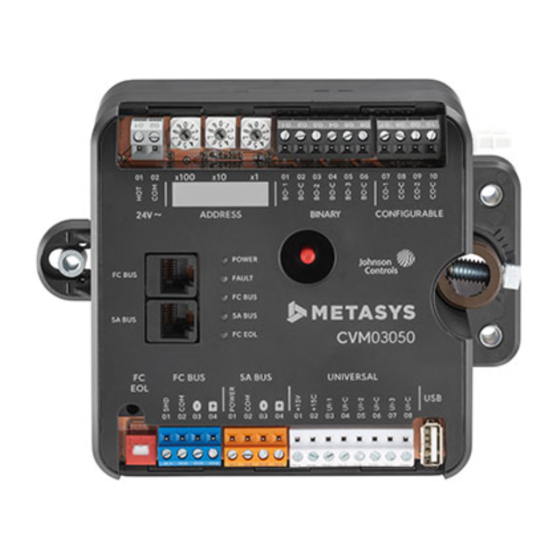
CV series controllers feature an integral damper actuator,
a digital Differential Pressure Transmitter (DPT) sensor,
and a 32-bit microprocessor. The CVM03050-0P and
CVE03050-0P models feature an integral potentiometer
to sense actual VAV box damper position. For information
on configuring an application with integrated actuator
feedback, refer to the M4-CV Series Actuator Feedback
Application Note (LIT-12013631).
CV series controllers also include an integral real-time
clock, which enables the controllers to monitor and
control schedules, calendars, and trends, and operate
for extended periods of time as stand-alone controllers
when offline from the Metasys system network. These
controllers connect easily to the wired and wireless
network sensors for zone and discharge air temperature
sensing. Their small package size facilitates quick
field installation and efficient use of space without
compromising control performance.
Communications protocols
CV series controllers can communicate using multiple
communication protocols depending on model and
configuration. The CVE controllers communicate using
the BACnet/IP communication protocol. CVM controllers
communicate using the BACnet MS/TP, N2, or wireless
Zigbee
communications protocols, with the addition
®
of ZFR183x Pro Wireless Field Bus Routers. Equipment
Controllers in BACnet/IP or BACnet/MSTP communication
mode are BACnet network-compliant devices. The
BACnet protocol is a standard for ANSI, ASHRAE, and the
International Standards Organization (ISO) for building
controls.
Controllers running in N2 mode can be used to maintain
or modernize sites with installed legacy Johnson Controls
controllers. For installation and commissioning support,
and tips for efficient and safe replacement, refer
to the Modernization Guide for Legacy N2 Controllers
(LIT-12012005) and the controller-specific documentation.
For information about mapping N2 Objects in controllers
with switchable communications protocols, refer to the
N2 Compatibility Options chapter of the Controller Tool Help
(LIT-12011147).
M4-CV Series VAV Box Controllers Installation
Setting a
®
To configure CVM controllers to communicate using
the N2 communications protocol, see
communications (CVM models
To configure CVM controllers to communicate using
the wireless communications protocol, see
wireless communications (CVM models
North American Emissions Compliance
United States
This equipment has been tested and found to comply
with the limits for a Class A digital device pursuant to
Part 15 of the FCC Rules. These limits are designed
to provide reasonable protection against harmful
interference when this equipment is operated in a
commercial environment. This equipment generates,
uses, and can radiate radio frequency energy and, if not
installed and used in accordance with the instruction
manual, may cause harmful interference to radio
communications. Operation of this equipment in a
residential area may cause harmful interference, in which
case the users will be required to correct the interference
at their own expense.
Canada
This Class (A) digital apparatus meets all the
requirements of the Canadian Interference-Causing
Equipment Regulations.
Cet appareil numérique de la Classe (A) respecte toutes
les exigences du Règlement sur le matériel brouilleur du
Canada.
Installation
Observe the following guidelines when installing the
controller:
• To minimize vibration and shock damage to the
controller, transport the controller in the original
container.
• Verify that all parts shipped with the controller.
• Do not drop the controller or subject it to physical
shock.
Parts included
• One CVM/CVE controller with removable terminal
blocks (Input/Output, Power, FC, and SA terminal blocks
bus are removable)
Note: The FC terminal block is only available with
the CVM model
• One installation instructions sheet
• One self-drilling No. 10 x 25 mm (1 in.) screw
*241014301590D*
Guide
Part No. 24-10143-01590 Rev. D
2022-02-07
Configuring N2
only).
Configuring
only).
(barcode for factory use only)
M4-CVM03050-0x, M4-CVE03050-0P
11.0
Advertisement
Table of Contents

Related Manuals for Johnson Controls M4-CV Series


Summary of Contents for Johnson Controls M4-CV Series
- Page 1 Operation of this equipment in a feedback, refer to the M4-CV Series Actuator Feedback residential area may cause harmful interference, in which Application Note (LIT-12013631).
-
Page 2: Materials And Special Tools Needed
• Use shims or washers to mount the controller securely and evenly on the mounting surface. • Mount the controller in an area free of corrosive vapors that matches the ambient conditions specified in the Technical specifications section. M4-CV Series VAV Box Controllers Installation Guide... - Page 3 45° and 60° VAV boxes, the actuator stroke time movement in either direction. must be adjusted. Refer to Controller Tool Help (LIT-12011147) for instructions on setting the actuator stroke time in the application. M4-CV Series VAV Box Controllers Installation Guide...
-
Page 4: Terminal Blocks And Bus Ports
For information about removing a terminal block, see Removing a terminal Observe the following guidelines when wiring a CVM/CVE block. For more information about I/O terminal functions, controller: requirements, and ratings, see Table 5. M4-CV Series VAV Box Controllers Installation Guide... - Page 5 Wiring for a daisy chained device on SA Bus Cable shield connection Note: Connect the shields to ensure they are continuous the entire length with only one ground location. Connects to the next device on the SA Bus M4-CV Series VAV Box Controllers Installation Guide...
-
Page 6: Supply Power Terminal Block
Table 4: Supply power terminal block wiring Description Supply power terminal block Supply power terminal header Wires from Johnson Controls 24 VAC, class 2 power transformer COM (Brown wire) 24 VAC (Orange wire) Note: The supply power wire colors may be different on transformers from other manufacturers. -
Page 7: Terminal Wiring Guidelines, Functions, Ratings, And Requirements
Note: If you are using the CVM03050 controller with the Wireless Field Bus System, refer to the WNC1800/ ZFR182x Pro Series Wireless Field Bus System Bulletin (LIT-12012320) or the ZFR1800 Series Wireless Field Bus System Bulletin (LIT-12011336). M4-CV Series VAV Box Controllers Installation Guide... - Page 8 RTD (1k Nickel [Johnson Controls sensor] 1k Platinum, and A99B Silicon Temperature Sensor) Negative Temperature Coefficient (NTC) Sensor 10K Type L (10K Johnson Controls Type II is equivalent to Type L) or 2.252K Type II Binary Input - Dry Contact Maintained Mode See Guideline A in Table 6.
-
Page 9: Cable And Wire Length Guidelines
Note: Figure 10 applies to low-voltage (<30 V) inputs and outputs only. Use the following figure to estimate the maximum cable length relative to the wire size and the load current (in mA) when wiring inputs and outputs. M4-CV Series VAV Box Controllers Installation Guide... -
Page 10: Communications Bus And Supply Power Wiring Guidelines
24 AWG 3-pair CAT 3 Cable <30.5m FC BUS (Port) (CVM models) FC Bus Communications. (100 ft) FC Bus provides 15 VDC Power for: • MAP Gateway • Wireless ZigBee Field Bus Router M4-CV Series VAV Box Controllers Installation Guide... -
Page 11: Termination Diagrams
The FC Bus and SA Bus wiring recommendations in this table are for MS/TP Bus communications at 38.4k baud. Termination diagrams A set of Johnson Controls termination diagrams provides details for wiring inputs and outputs to the controllers. See the figures in this section for the applicable termination diagrams. - Page 12 Temperature Sensor UI Dry Contact 0–10 VDC Output to Actuator (External Source) 0–10 VDC Output to Actuator (Internal Source) 24 VAC Triac Output (Switch Low, External Source) Note: Applies to CO4 and CO5. M4-CV Series VAV Box Controllers Installation Guide...
- Page 13 Actuator (Switch Low, Internally Sourced) Note: Applies to BO3 (for only), BO1, and BO2. 24 VAC Binary Output (Switch Low, Internally Sourced) Network Stat with SA Bus Phone Jack (Fixed Address = 199) M4-CV Series VAV Box Controllers Installation Guide...
-
Page 14: Setup And Adjustments
Note: In wireless network applications, do from N2 to MS/TP not connect any wires to the FC Bus terminal block. (Connect the SA/FC terminal block on About this task: an expansion module to an SA Bus only.) M4-CV Series VAV Box Controllers Installation Guide... - Page 15 (MSB) to least significant bit (LSB). In Figure 11, the switches are set to 1 2 3, designating this controller as controller number 123. The controller M4-CV Series VAV Box Controllers Installation Guide...
-
Page 16: Removing A Terminal Block
N2 mode. These the FC Bus. connection options require additional hardware listed in Table 12. Determine if the controller must be set as a terminating device on the bus. M4-CV Series VAV Box Controllers Installation Guide... - Page 17 The most common cause of this problem is when the 24 VAC power supply on the controller is reversed but not reversed on a connected secondary device. M4-CV Series VAV Box Controllers Installation Guide...
-
Page 18: Led Status And States
ETH-2 (CVE Green Off Steady = ETH-2 is not connected models) Blinking = ETH-2 connected and communicating FAULT Green Both blink six times in sequence = no valid firmware on the device SA BUS M4-CV Series VAV Box Controllers Installation Guide... -
Page 19: General Troubleshooting
0–10V output has an undesirable offset of up Correction: and verify the commanded value is to 1 V. Connect the CO-C terminal of the present. The Common Reference is incorrect. configurable output to the common of the connected end device. M4-CV Series VAV Box Controllers Installation Guide... - Page 20 Input and Output terminal block replacement kit for SNC, CGM, CGE, CVM, CVE, and XPM products. Kit includes 5 of each 2, 3, and 4 position Input and Output terminal blocks. 30 terminal blocks in total. M4-CV Series VAV Box Controllers Installation Guide...
-
Page 21: Technical Specifications
The FIT can be used on both the FC Bus and SA Bus. TL-BRTRP-0 Portable BACnet/IP to MS/TP Router M4-CVACT-0R Actuator Assembly Replacement Kit for use with M4-CV series controllers Technical specifications Table 13: CV Series controllers technical specifications Description Power Requirement... -
Page 22: Repair Information
The performance specifications are nominal and conform to acceptable industry standard. For application at conditions beyond these specifications, consult the local Johnson Controls office. Johnson Controls shall not be liable for damages resulting from misapplication or misuse of its products. -
Page 23: Contact Information
MANAGEMENT 6101 XK ECHT MILWAUKEE WI 53202 NO. 32 CHANGJIANG RD NEW DISTRICT THE NETHERLANDS WUXI JIANGSU PROVINCE 214028 CHINA Contact information Contact your local branch office: www.johnsoncontrols.com/locations Contact Johnson Controls: www.johnsoncontrols.com/ contact-us M4-CV Series VAV Box Controllers Installation Guide... - Page 24 © 2022 Johnson Controls. All rights reserved. All specifications and other information shown were current as of document revision and are subject to change without notice. www.johnsoncontrols.com...
Need help?
Do you have a question about the M4-CV Series and is the answer not in the manual?
Questions and answers