Table of Contents
Advertisement
Quick Links
Application
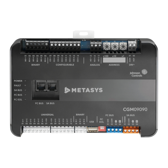
The CG series general purpose application controllers
are well-suited for controlling a wide variety of facility
and HVAC equipment, including fan coils, air handling
units, packaged HVAC equipment, and central plant
equipment. CG series controllers run pre-engineered and
user-programmed applications.
CG series controllers include an integral real-time clock,
which enables the controllers to monitor and control
schedules, calendars, and trends, and operate for
extended periods of time as standalone controllers when
offline from the Metasys system network.
Communications Protocols
CG series controllers can communicate using multiple
communication protocols depending on model and
configuration. CGE controllers communicate using the
BACnet
/IP communication protocol. CGM controllers
®
communicate using the BACnet MS/TP, N2 or wireless
Zigbee
communications protocols, with the addition of
®
ZFR183x Pro Wireless Field Bus Routers.
Equipment controllers in BACnet/IP or BACnet MS/TP
communication mode are BACnet network-compliant
devices. The BACnet protocol is a standard for ANSI,
ASHRAE, and the International Standards Organization
(ISO) for building controls.
Controllers running in N2 mode can be used to maintain
or modernize sites with installed legacy Johnson Controls
controllers. For installation and commissioning support,
and tips for efficient and safe replacement, refer
to the Modernization Guide for Legacy N2 Controllers
(LIT-12012005) and the controller-specific documentation.
For information about mapping N2 Objects in controllers
with switchable communications protocols, refer to the
N2 Compatibility Options chapter of the Controller Tool Help
(LIT-12011147). To configure CGM series controllers to
communicate using the N2 communications protocol, see
Configuring N2 communications (CGM models
To configure CGM controllers to communicate using
the wireless communications protocol, see
wireless communications (CGM models
M4-CG Series General Purpose Application
North American Emissions Compliance
United States
This equipment has been tested and found to comply
with the limits for a Class A digital device pursuant to
Part 15 of the FCC Rules. These limits are designed
to provide reasonable protection against harmful
interference when this equipment is operated in a
commercial environment. This equipment generates,
uses, and can radiate radio frequency energy and, if not
installed and used in accordance with the instruction
manual, may cause harmful interference to radio
communications. Operation of this equipment in a
residential area may cause harmful interference, in which
case the users will be required to correct the interference
at their own expense.
Canada
This Class (A) digital apparatus meets all the
requirements of the Canadian Interference-Causing
Equipment Regulations.
Cet appareil numérique de la Classe (A) respecte toutes
les exigences du Règlement sur le matériel brouilleur du
Canada.
Installation
®
Observe the following guidelines when installing the
controller:
• To minimize vibration and shock damage to the
• Verify that all parts shipped with the controller.
• Do not drop the controller or subject it to physical
only).
Parts included
• One CGM/CGE controller with removable terminal
Configuring
only).
• One installation instructions sheet
Materials and special tools needed
• Three fasteners appropriate for the mounting surface
• One 20 cm (8 in.) or longer piece of 35 mm DIN rail and
• Small straight-blade (1/8 in. or 3.2 mm) or Philips #2
Controller Installation Guide
controller, transport the controller in the original
container.
shock.
blocks (Input/Output, Power, FC, and SA Bus terminal
blocks are removable)
Note: The FC terminal block is only available with the
CGM model.
(M4 screws or #8 screws)
appropriate hardware for DIN rail mount (only)
screwdriver for securing wires in the terminal blocks
*241014301698D*
M4-CGM09090-0x, M4-CGM04060-0, M4-
Part No. 24-10143-01698 Rev. D
11.0
2022-02-07
(For factory use only)
CGE09090-0x, M4-CGE04060-0
Advertisement
Table of Contents

Related Manuals for Johnson Controls M4-CG Series


Summary of Contents for Johnson Controls M4-CG Series
- Page 1 ASHRAE, and the International Standards Organization (ISO) for building controls. Installation Controllers running in N2 mode can be used to maintain or modernize sites with installed legacy Johnson Controls ® Observe the following guidelines when installing the controllers. For installation and commissioning support,...
-
Page 2: Physical Features
DIN rail, and any user-supplied enclosure. and observe the Ambient Conditions requirements in • Mount the controller horizontally on 35 mm DIN rail Table 11. whenever possible. • Mount the controller in the proper mounting position. M4-CG Series General Purpose Application Controller Installation Guide... -
Page 3: Mounting Features And Dimensions
Mounting features and dimensions, or hold the controller up to the wall or surface in a proper mount position and mark the hole locations through the mounting clips. M4-CG Series General Purpose Application Controller Installation Guide... -
Page 4: Terminal Blocks And Bus Ports
Redundancy Protocol (MRP). With MRP, a ring of Ethernet l'équipement. devices can overcome any single communication failure, with a recovery time faster than a non-ring (daisy chain or star) architecture. M4-CG Series General Purpose Application Controller Installation Guide... - Page 5 MAP Gateway, the VAV Balancing Tool, the DLK0350, DIS1710 local controller display, specified network sensors, or other SA Bus devices with RJ-12 plugs. When the controller is M4-CG Series General Purpose Application Controller Installation Guide...
-
Page 6: Supply Power Terminal Block
Supply power terminal header frequency noise. • Cable runs of less than 30 m (100 ft) often do not Wires from Johnson Controls 24 VAC, class 2 power require an offset in the input/output software setup. transformer • Cable runs over 30 m (100 ft) often require an offset in 24 VAC (Orange wire) the input/output software setup. - Page 7 See Guideline C in Table 4. Connects COn to CO-C or CO-Cn when activated. External Power Source Requirements: 24 VAC maximum output voltage 0.5 A maximum output current 40 mA minimum load current M4-CG Series General Purpose Application Controller Installation Guide...
- Page 8 40 mA minimum load current BO-C or BO- Binary Output Common for all Binary Output terminals. Note: Each Binary Output Common terminal is isolated from all other commons, including other Binary Output Common terminals. M4-CG Series General Purpose Application Controller Installation Guide...
-
Page 9: Cable And Wire Length Guidelines
(in mA) when wiring inputs and outputs. Figure 10: Maximum wire length for low-voltage (<30 V) Inputs and Outputs by current and wire size M4-CG Series General Purpose Application Controller Installation Guide... -
Page 10: Communications Bus And Supply Power Wiring Guidelines
0.8 mm to 1.0 mm Supplies 20–30 VAC (Nominal 24 VAC) (18 AWG) 2-wire < 30 m (100 ft) 24 VAC Power Supply Common (Isolated from all other Common terminals on controller) 14 VA M4-CG Series General Purpose Application Controller Installation Guide... -
Page 11: Termination Diagrams
Technical Bulletin (LIT-12011034). Termination diagrams A set of Johnson Controls termination diagrams provides details for wiring inputs and outputs to the controllers. See the figures in this section for the applicable termination diagrams. Note: The CGM04060 and CGE04060 models do not have analog outputs. References to the analog output apply to the CGM09090 and CGE09090 models only. - Page 12 Output Voltage Input (Self-Powered) Current Input - External Source (Isolated) Current Input - Internal Source (2- wire) Current Input - Internal Source (3 wire) Current Input - External Source (in Loop) M4-CG Series General Purpose Application Controller Installation Guide...
- Page 13 Type of Input/ Termination diagrams device Output Feedback from EPP-1000 Dry Contact UI or BI (Binary Input) 0–10 VDC Output to Actuator (External Source) 0–10 VDC Output to Actuator (Internal Source) Current Output M4-CG Series General Purpose Application Controller Installation Guide...
- Page 14 Termination diagrams device Output 24 VAC Triac Output (Switch Low, External Source) Analog Output (Current) 4–20 mA Output to Actuator 4–20 mA Output to Actuator Incremental Control to Actuator (Switch Low, Externally Sourced) M4-CG Series General Purpose Application Controller Installation Guide...
- Page 15 Network Stat with SA Bus Phone Jack (Fixed Address = 199) Note: The bottom jack (J2) on the TE-700 and TE-6x00 Series Sensors is not usable as a zone bus or an SAB connection. M4-CG Series General Purpose Application Controller Installation Guide...
-
Page 16: Setup And Adjustments
Setting the device address on CGM models. Reconnect the 24 VAC supply to the controller. Using an SA Bus connection, download the firmware and controller application file configured for N2 to the controller. M4-CG Series General Purpose Application Controller Installation Guide... - Page 17 1 2 3, designating this controller's In Figure 11, the switches are set to 1 2 3, designating device address as 123. this controller as controller number 123. The controller M4-CG Series General Purpose Application Controller Installation Guide...
-
Page 18: Removing A Terminal Block
Determine the physical location of the controller on the FC Bus. Determine if the controller must be set as a terminating device on the bus. M4-CG Series General Purpose Application Controller Installation Guide... -
Page 19: Setting Up A Local Display
Apply power to the off. controller and connect to the device with either a MAP M4-CG Series General Purpose Application Controller Installation Guide... -
Page 20: Commissioning The Controller
Off Steady = ETH-2 is not connected models) Blinking = ETH-2 connected and communicating FAULT Both blink six times in sequence = no valid firmware on the device ( Applicable to CGE models only) SA BUS Green M4-CG Series General Purpose Application Controller Installation Guide... - Page 21 XPM products. Kit includes 5 of each 2, 3, and 4 position Input and Output terminal blocks. ACC-TBKPWFCSA-0 Power, FC Bus, and SA Bus terminal block replacement kit for SNC, CGM, CGE, CVM, CVE, and XPM products. Kit includes 5 of each terminal block type. M4-CG Series General Purpose Application Controller Installation Guide...
-
Page 22: Technical Specifications
16 MB flash memory and 8 MB SDRAM Real-Time Clock Backup Power Supply Super capacitor maintains power to the onboard real-time clock for a minimum of 72 hours when supply power to the controller is disconnected. M4-CG Series General Purpose Application Controller Installation Guide... - Page 23 The performance specifications are nominal and conform to acceptable industry standard. For application at conditions beyond these specifications, consult the local Johnson Controls office. Johnson Controls shall not be liable for damages resulting from misapplication or misuse of its products.
-
Page 24: Repair Information
Contact information Contact your local branch office: www.johnsoncontrols.com/locations Contact Johnson Controls: www.johnsoncontrols.com/ contact-us © 2022 Johnson Controls. All rights reserved. All specifications and other information shown were current as of document revision and are subject to change without notice. www.johnsoncontrols.com...
Need help?
Do you have a question about the M4-CG Series and is the answer not in the manual?
Questions and answers