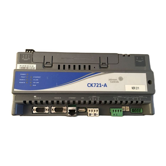
Johnson Controls CK721-A Hardware Installation Manual
Network controller
Hide thumbs
Also See for CK721-A:
- Installation and operation manual (234 pages) ,
- Factory field upgrade (22 pages) ,
- Factory field installation (21 pages)
Subscribe to Our Youtube Channel
Summary of Contents for Johnson Controls CK721-A
- Page 1 CK721-A Network Controller hardware installation manual 24-10025-237 Revision – December 2017...
- Page 2 No part of this document may be reproduced without the prior permission of Johnson Controls. If this document is translated from the original English version by Johnson Controls, all reasonable endeavors will be used to ensure the accuracy of translation. Johnson Controls. shall not be liable for any translation errors contained herein or for incidental or consequential damages in connection with the furnishing or use of this translated material.
- Page 3 2. The CK721-A shall be mounted in subassembly S300-DIN-L or S300-DIN-S. 3. The CK721-A in combination with the S300-DIN-L or S300-DIN-S must be connected to a UL Listed Uninterruptible Power Supply that provides a minimum of 24 hours of AC emergency power.
-
Page 5: General Description
Battery bracket kit for either S300-DIN-L or S300-DIN-S. S300-BAT-2.8AH Battery for uninterruptible power operation or use in S300-DIN-S. Two backup batteries are used per enclosure, 12V, 2.8Ah 1. CK721-A firmware V3.3 and higher also allows for use of Legacy S300 devices under P2000 V3.13 or higher. -
Page 6: System Configuration Example
Figure 1: Example of a Simple CK721-A System Configuration CK721-A Encrypted Communications with the Server When enabled, encrypted network communications between the CK721-A controller and the server uses the Advanced Encryption Standard (AES256). The CK721-A Encryption is implemented using the Federal Information Processing Standards (FIPS) 140-2, validated (Certificate #2398), cryptographic module (version 2.0.9) from the Open Source... - Page 7 Wiring Binary Inputs on page 5. Output point Form C Relay, SPDT, 24 VDC maximum The CK721-A provides a relay output for connecting to an external alarm at Binary Out1. The relay will switch 2A at 24 VDC. Connectors RS232 A RS-232 Serial Interface, DB9 port for the user interface to a terminal emulator (workstation or laptop computer).
-
Page 8: Setting The End-Of-Line Switch
: Before you replace the lithium battery (recommended every five years or after extended MPORTANT use), ensure AC power or backup battery power is supplied to the CK721-A. If AC power or backup battery power is not supplied before you remove the lithium battery, the realtime clock will be incorrect. - Page 9 Installation Manual. Mounting the CK721-A The CK721-A module is mounted on a backplate’s DIN rail. To mount a module, align it with the rail and snap on. To remove a module, pull the white clips (two are located at the bottom and one on top of the module), then pull the bottom of the module out and lift it up.
- Page 10 CK721-A Network Controller Hardware Installation 24-10025-237 Rev. – Connecting CK721-A to the Network The CK721-A RJ45 port is designed to connect to a switch using pins 1, 2, 3, and 6, wired straight through. RXD- Output Transmit Data - RxD+...
- Page 11 42V or Magnetic door locks without EMI suppression. Every unit in a Johnson Controls installation must have its chassis bonded to a verified electrical ground (earth). In all cases, the local wiring codes apply.
-
Page 12: Basic Commissioning
Figure 6: Power Wiring in Small Enclosure For power wiring in the large enclosure, use the pre-wired power cable assembly provided with the CK721-A. Connect the wires to the existing cable assembly from the power supply as shown Figure +24VDC... - Page 13 Using your Terminal Emulation To start communication: 1. Connect the cables, according to the connection method you will be following: • Serial cable between RS232C A (J3) of the CK721-A controller and your laptop or PC serial port, or • Ethernet cable 2.
-
Page 14: Basic Panel Configuration
Hardware Installation 24-10025-237 Rev. – : You have three chances to login to the CK721-A panel. After three attempts, the CK721-A disables login for about five minutes, after which time you may try again. (Both login and password are case-sensitive.) 7. - Page 15 4. Set the Preferred Primary Comm Path to Y. 5. Set the Network Polling [LAN] setting which specifies the frequency (in seconds) that the CK721-A panel polls the P2000 server during LAN connections. The recommended value is 30 seconds. The Network Polling [Dup] value is not currently used.
-
Page 16: Panel Screen
CK721-A Network Controller Hardware Installation 24-10025-237 Rev. – Panel Screen The Panel screen is used when the CK721-A panel is configured for the P2000 server. Table 7: Panel Screen Field Description Field Type Description Panel Name User Def. The panel name is defined at the server, and then downloaded from the server to the panel. -
Page 17: Maintenance
AINTENANCE This section provides maintenance instructions, operational testing procedures, troubleshooting guidelines, and instructions on how to obtain replaceable parts for the CK721-A system. To perform the following routine maintenance on the CK721-A: 1. Periodically check the continuity of the grounding circuit. -
Page 18: Impaired Performance Conditions
Backup battery not replaced correctly. This section (Maintenance). Field Servicing Troubleshoot the CK721-A by substituting the suspected defective panel with a new component. All replaceable parts are available from Johnson Controls. Consult your Customer Success Center representative at (800) 482-2778 for domestic orders or... - Page 19 Security Solutions (805) 522-5555 www.johnsoncontrols.com We welcome your comments at BE-techpubs-security@jci.com.


Need help?
Do you have a question about the CK721-A and is the answer not in the manual?
Questions and answers