Table of Contents
Advertisement
Quick Links
Application
The CV series controllers are designed for variable air
volume (VAV) box applications.
CV series controllers feature 14 preloaded standard
applications to allow this controller to operate
standard VAV box equipment with a proven energy-
efficient sequence of operation, without the need for
programming. For information on configuring a CV series
controller to use a preloaded application, see
preloaded
application. These controllers are also fully
programmable, using the Controller Configuration Tool
(CCT), providing the flexibility to create custom control
sequences.
CV series controllers feature an integral damper actuator,
a digital Differential Pressure Transmitter (DPT) sensor,
and a 32-bit microprocessor. The CVM03050-0P and
CVE03050-0P models feature an integral potentiometer to
sense actual VAV box damper position.
CV series controllers also include an integral real-time
clock, which enables the controllers to monitor and
control schedules, calendars, and trends, and operate
for extended periods of time as stand-alone controllers
when offline from the Facility Explorer system network.
These controllers connect easily to the wired and
wireless network sensors for zone and discharge air
temperature sensing. Their small package size facilitates
quick field installation and efficient use of space without
compromising control performance.
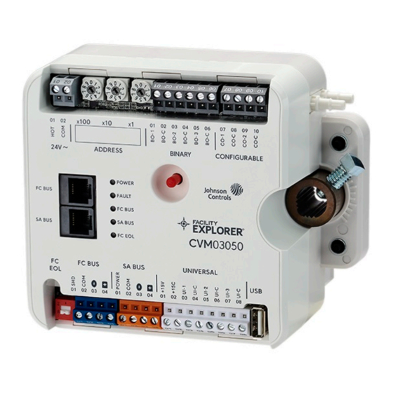
Figure 1: F4-CVM3050
F4-CV Series VAV Terminal Equipment
Controllers Installation Guide
Communications protocols
CV series controllers can communicate using multiple
communication protocols depending on model and
configuration. The CVE controllers communicate using
the BACnet/IP communication protocol. CVM controllers
communicate using the BACnet MS/TP communications
protocols, with the addition of ZFR183x Pro Wireless
Field Bus Routers. Equipment Controllers in BACnet/IP or
BACnet/MSTP communication mode are BACnet network-
Setting a
compliant devices. The BACnet protocol is a standard
for ANSI, ASHRAE, and the International Standards
Organization (ISO) for building controls.
To configure CVM controllers to communicate using
the wireless communications protocol, see
wireless communications (CVM models
North American Emissions Compliance
United States
This equipment has been tested and found to comply
with the limits for a Class A digital device pursuant to
Part 15 of the FCC Rules. These limits are designed
to provide reasonable protection against harmful
interference when this equipment is operated in a
commercial environment. This equipment generates,
uses, and can radiate radio frequency energy and, if not
installed and used in accordance with the instruction
manual, may cause harmful interference to radio
communications. Operation of this equipment in a
residential area may cause harmful interference, in which
case the users will be required to correct the interference
at their own expense.
Canada
This Class (A) digital apparatus meets all the
requirements of the Canadian Interference-Causing
Equipment Regulations.
Cet appareil numérique de la Classe (A) respecte toutes
les exigences du Règlement sur le matériel brouilleur du
Canada.
Installation
Observe the following guidelines when installing the
controller:
• To minimize vibration and shock damage to the
controller, transport the controller in the original
container.
• Verify that all parts shipped with the controller.
• Do not drop the controller or subject it to physical
shock.
Part No. 24-10143-01809 Rev. D
Configuring
only).
*241014301809D*
(barcode for factory use only)
F4-CVM03050-0, F4-CVM03050-0P
11.0
2022-04-05
Advertisement
Table of Contents

Related Manuals for Johnson Controls F4-CV Series


Summary of Contents for Johnson Controls F4-CV Series
- Page 1 F4-CV Series VAV Terminal Equipment Controllers Installation Guide Part No. 24-10143-01809 Rev. D 11.0 2022-04-05 Application Communications protocols CV series controllers can communicate using multiple The CV series controllers are designed for variable air communication protocols depending on model and volume (VAV) box applications.
-
Page 2: Parts Included
FC Bus Port: RJ-12 6-Pin Modular Jack. See . (CVM only) Captive Spacer and Screw. LED Status Indicators. See Table. Ethernet Ports: ETH-1 and ETH-2. See BACnet/IP Ethernet Network Topology for CVE controllers F4-CV Series VAV Terminal Equipment Controllers Installation Guide... - Page 3 45° and 60° boxes. The closed damper seal provides the full-closed stop. To mount the CVM/CVE controllers, complete the following steps: Set all the switches on the equipment controller to their known settings. F4-CV Series VAV Terminal Equipment Controllers Installation Guide...
- Page 4 Use proper electrostatic discharge precautions during installation, setup, and servicing to avoid damaging the controller. For information on configuring and wiring a BACnet/ IP network, refer to theFX MS/TP Communications Bus Technical Bulletin (LIT-12011670). F4-CV Series VAV Terminal Equipment Controllers Installation Guide...
-
Page 5: Terminal Blocks And Bus Ports
FC Bus devices in a daisy-chain configuration using 3-wire twisted, shielded cable as shown in Figure 6. For more information about FC Bus terminal functions, requirements, and ratings, see Table 7. F4-CV Series VAV Terminal Equipment Controllers Installation Guide... -
Page 6: Modular Ports
Transmitter, and NS Series sensors. Note: The order of the HOT and COM terminals on the CV series controllers is reversed from the order of the terminals on the CG series controllers. F4-CV Series VAV Terminal Equipment Controllers Installation Guide... -
Page 7: Terminal Wiring Guidelines, Functions, Ratings, And Requirements
Description Supply power terminal block Supply power terminal header Risque de dommages matériels: Wires from Johnson Controls 24 VAC, class 2 power Ne mettez pas l’appareil sous tension avant d’avoir transformer vérifié toutes les connexions du câblage. Le câblage inadéquat de cette borne peut causer un court- COM (Brown wire) circuit sur l’alimentation électrique de 24 V c. - Page 8 RTD (1k Nickel [Johnson Controls sensor] 1k Platinum, and A99B Silicon Temperature Sensor) Negative Temperature Coefficient (NTC) Sensor 10K Type L (10K Johnson Controls Type II is equivalent to Type L) or 2.252K Type II Binary Input - Dry Contact Maintained Mode See Guideline A in Table 6.
-
Page 9: Cable And Wire Length Guidelines
Note: Figure 11 applies to low-voltage (<30 V) inputs and outputs only. Use the following figure to estimate the maximum cable length relative to the wire size and the load current (in mA) when wiring inputs and outputs. F4-CV Series VAV Terminal Equipment Controllers Installation Guide... -
Page 10: Communications Bus And Supply Power Wiring Guidelines
24 AWG 3-pair CAT 3 Cable <30.5m FC BUS (Port) (CVM models) FC Bus Communications. (100 ft) FC Bus provides 15 VDC Power for: • MAP Gateway • Wireless ZigBee Field Bus Router F4-CV Series VAV Terminal Equipment Controllers Installation Guide... -
Page 11: Termination Diagrams
The FC Bus and SA Bus wiring recommendations in this table are for MS/TP Bus communications at 38.4k baud. Termination diagrams A set of Johnson Controls termination diagrams provides details for wiring inputs and outputs to the controllers. See the figures in this section for the applicable termination diagrams. - Page 12 Temperature Sensor UI Dry Contact 0–10 VDC Output to Actuator (External Source) 0–10 VDC Output to Actuator (Internal Source) 24 VAC Triac Output (Switch Low, External Source) Note: Applies to CO4 and CO5. F4-CV Series VAV Terminal Equipment Controllers Installation Guide...
- Page 13 Actuator (Switch Low, Internally Sourced) Note: Applies to BO3 (for only), BO1, and BO2. 24 VAC Binary Output (Switch Low, Internally Sourced) Network Stat with SA Bus Phone Jack (Fixed Address = 199) F4-CV Series VAV Terminal Equipment Controllers Installation Guide...
-
Page 14: Setup And Adjustments
(MSB) to least significant bit (LSB) when the controller is oriented. . In the following figure, the switches are set Result to 1 2 3, designating this controller's device address as 123. F4-CV Series VAV Terminal Equipment Controllers Installation Guide... -
Page 15: Removing A Terminal Block
When the Fault LED turns off, connect to the device with either a MAP Gateway, FX-DLK03050, or FX-DIS1710-0 Local Display to view the points in the controller. F4-CV Series VAV Terminal Equipment Controllers Installation Guide... -
Page 16: Commissioning The Controllers
SCR Elec Reheat Series Fan W/C Adj Single Duct SCR Electric Reheat/Proportional Heating Valve, Single Speed Series Fan, Warm/Cool Adjust SCR Elec Reheat Parallel Fan W/C Adj Single Duct SCR Electric Reheat/Proportional Heating Valve, Parallel Fan, Warm/Cool Adjust F4-CV Series VAV Terminal Equipment Controllers Installation Guide... -
Page 17: Led Status And States
Green Off Steady = ETH-2 is not connected models) Blinking = ETH-2 connected and communicating FAULT Green Both blink six times in sequence = no valid firmware on the device SA BUS F4-CV Series VAV Terminal Equipment Controllers Installation Guide... -
Page 18: General Troubleshooting
Correction: and verify the commanded value is to 1 V. Connect the CO-C terminal of the present. The Common Reference is incorrect. configurable output to the common of the connected end device. F4-CV Series VAV Terminal Equipment Controllers Installation Guide... - Page 19 Input and Output terminal block replacement kit for SNC, CGM, CGE, CVM, CVE, and XPM products. Kit includes 5 of each 2, 3, and 4 position Input and Output terminal blocks. 30 terminal blocks in total. F4-CV Series VAV Terminal Equipment Controllers Installation Guide...
-
Page 20: Technical Specifications
The FIT can be used on both the FC Bus and SA Bus. F4-CVACT-0R Actuator Assembly Replacement Kit for use with F4-CV series controllers Technical specifications Table 13: CV Series controllers technical specifications Description... -
Page 21: Repair Information
The performance specifications are nominal and conform to acceptable industry standard. For application at conditions beyond these specifications, consult the local Johnson Controls office. Johnson Controls shall not be liable for damages resulting from misapplication or misuse of its products. -
Page 22: Contact Information
Contact information Contact your local branch office: www.johnsoncontrols.com/locations Contact Johnson Controls: www.johnsoncontrols.com/ contact-us © 2022 Johnson Controls. All rights reserved. All specifications and other information shown were current as of document revision and are subject to change without notice. www.johnsoncontrols.com...
Need help?
Do you have a question about the F4-CV Series and is the answer not in the manual?
Questions and answers