
Subscribe to Our Youtube Channel
Related Manuals for Johnson Controls CIS01


Summary of Contents for Johnson Controls CIS01
- Page 1 Operation Manual Simplifi ed Wired Controller Model: CIS01 IMPORTANT: READ AND UNDERSTAND THIS MANUAL BEFORE USING THIS CONTROLLER. KEEP THIS MANUAL FOR FUTURE REFERENCE. P5415477...
-
Page 2: General Precautions
● Use only Johnson Controls recommended, provided as standardized, or replacement parts. ● Johnson Controls will not assume any liability for injuries or damage caused by not following steps outlined or described in this manual. Unauthorized modifi cations to Johnson Controls products are prohibited as they…... -
Page 3: Installation Precautions
Shielded cable must be used in all areas to reduce the potential for communication errors. When shielded cabling is applied, proper bonding and termination of the cable shield is required as per Johnson Controls guidelines. Plenum and riser ratings for communication cables must be considered per application and local code requirements. - Page 4 ● Be sure to install circuit breakers (ground fault interrupter, isolating switch, molded case circuit breaker, and so forth) with the specifi ed capacity. Ensure that the wiring terminals are tightened securely to recommended torque specifi cations. ● Clamp electrical wires securely with a cord clamp after all wiring is connected to the terminal block. In addition, run wires securely through the wiring access channel.
-
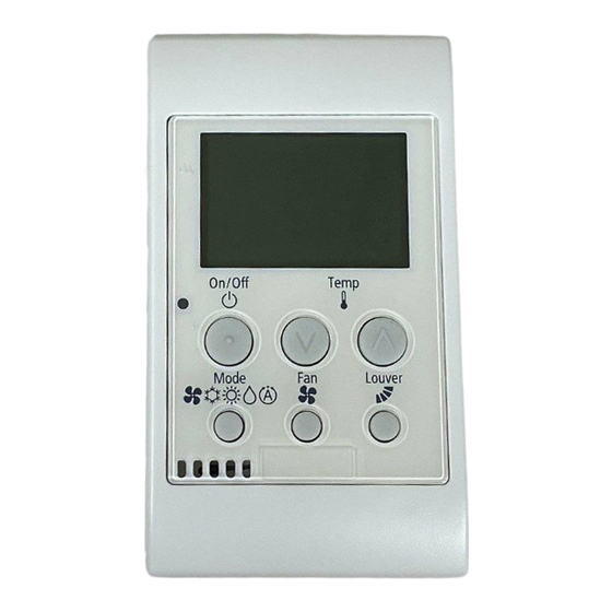
Page 5: Switch Names And Functions
2. Switch Names and Functions The fi gure below shows all the indications for reference. The actual display during operation is different. Setting Temperature Indicator Display Part Page 7) Alarm Code Indicator Page 10) Indicates when the air conditioner is in abnormal condition. -
Page 6: Operation Method
3. Operation Method Operation Mode Automatic Cooling/Heating Operation (Cooling, Heating, Dry, Cooling/Heating In case dual setpoint is selected in automatic Automatic and Airfl ow Operation) cooling/heating operation*, during auto mode both cooling setpoint and heating setpoint can be <Function> selected. * Cooling Operation (COOL): By default, temperature when the cooling/heating To decrease the room temperature. -
Page 7: Setting Method
4. Setting Method Temperature Setting Swing Louver Direction By pressing “Temp ˄ ”, the temperature is By pressing “Louver”, the louver direction changes increased by 1°F (0.5°C). (Max. 86°F (30°C)) as follows. By pressing “ ˅ Temp”, the temperature is decreased by 1°F (0.5°C). -
Page 8: Operation
5. Operation 6. Other Indicators Operation Start In Normal Conditions Press “On/Off”. 6.1.1 Central Control The run indicator turns ON and the operation When remote control operation is restricted (all initiates. functions) The central control “ ” turns ON. If the remote control restriction is set from the central controller, the settings for “RUN”, “Operation Mode”, “Temperature Setting”, “Fan Speed”, and “Louver”... - Page 9 6.1.4 Operation Control • Setback Operation • Supplying Electrical Power In case the setback operation is enabled and the The “ • ” is activated when electrical power is card key is removed, setpoint is compensated supplied to outdoor unit for the fi rst time or after and fan operate at “Low”...
- Page 10 In Alarm Conditions 6.2.1 Alarms • The RUN LED (Red) is fl ashing. • The indoor unit number, alarm code, model code, and the connected number of indoor units are displayed on LCD. • In cases where a number of indoor units are connected, the above items for each indoor unit are displayed one by one.
- Page 11 P5415477...
- Page 12 © 2018 Johnson Controls, Inc. P5415477-rev.3 LIT-12012042 Issued Oct, 2018...
Need help?
Do you have a question about the CIS01 and is the answer not in the manual?
Questions and answers