KEB COMBIVERT F5 Installation Manualline
Basic compact
Hide thumbs
Also See for COMBIVERT F5:
- Applications manual (378 pages) ,
- Reference manual (349 pages) ,
- Instruction manual (196 pages)
Table of Contents
Advertisement
Quick Links
Advertisement
Table of Contents

Subscribe to Our Youtube Channel
Related Manuals for KEB COMBIVERT F5


Summary of Contents for KEB COMBIVERT F5
- Page 1 C O M B I V E R T Installation Guideline Housing B 11/2004...
- Page 2 The safety and warning instructions specified in this manual do not lay claim on completeness. KEB reserves the right to change/adapt specifications and technical data without prior notice. The used pictograms...
-
Page 3: Table Of Contents
Table of Contents Safety and Operating Instructions ..............4 Product description ..................5 Intended use ........................5 Unit identification ......................5 Technical data ........................6 2.3.1 230 V class ......................... 6 2.3.2 400 V class ......................... 7 Dimensions and Terminals ..................... 8 Installation and Connection ................ -
Page 4: Safety And Operating Instructions
Important, absolutely read Safety and Operating Instructions Safety and Operating Instructions for drive converters (in conformity with the Low-Voltage Directive 73/23/EWG) The drive converters shall be protected against excessive 1. General strains. In particular, no components must be bent or In operation, drive converters, depending on their degree of isolating distances altered in the course of transportation protection, may have live, uninsulated, and possibly also... -
Page 5: Product Description
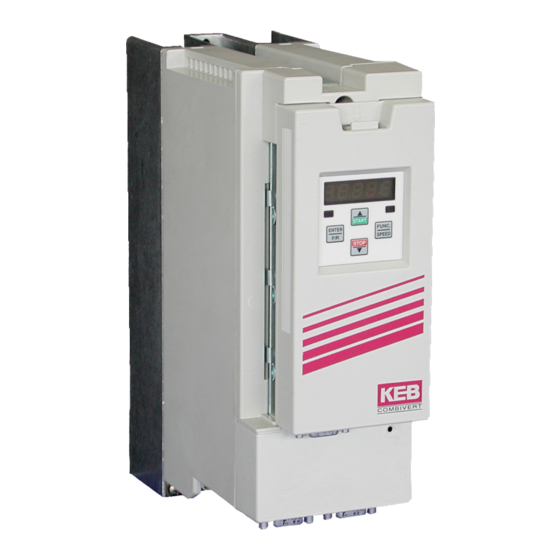
Product description Product description Intended use The frequency inverter KEB COMBIVERT F5 serves exclusively for the control and regulation of asynchronous motors. The operation of other electric consumers is prohibited and can lead to the destruction of the unit. Frequency inverter are components which are intended for the installation in electric systems or machines. -
Page 6: Technical Data
Product description Technical data 2.3.1 230 V class Inverter Size Housing size Phases Output rated pow er [kVA] Max. rated motor pow er [kW] 0,37 0,75 Output rated current Max. short time current 12,6 OC-tripping current 15,1 21,6 Input rated current [A] 4,6 14 9,8 20 14 Max. -
Page 7: 400 V Class
Product description 2.3.2 400 V class Inverter Size Housing size Phases Output rated pow er [kVA] 0,9 Max. rated motor pow er [kW] 0,37 0,75 Output rated current [A] 1,3 Max. short time current [A] 2,3 10,4 17 OC-tripping current [A] 2,8 12,5 21 Input rated current... -
Page 8: Dimensions And Terminals
Product description Dimensions and Terminals * with Operator Connection for mains voltage, motor, braking resistor and temperature detection Connection for control lines Connection for operator or HSP5 service cable Connection for shielding / earthing Pay attention to the input voltage, since 230V and 400V class (3-phase) are possible. -
Page 9: Installation And Connection
• Install all cables as close as possible to the mounting plate - ideal in a metal cable duct. • Mount COMBIVERT well conducting with the mounting plate. Remove the paint beforehand. You can find further instructions regarding the EMC-conform wiring in the Internet at KEB. -
Page 10: Connection Of Power Circuit
• T1, T2 Temperature sensor / switch (see chapter 3.3.6) 3.3.2 Wiring instructions Absolutely observe the connecting voltage of the KEB COMBIVERT. A 230V-unit will be immediately destructed on a 400V-power supply. Never exchange the mains and motor cables. Some countries demand that the PE-terminal is directly connected... -
Page 11: Mains Connection
Installation and Connection 3.3.3 Mains connection Mains connection 230 V 1-phase Mains connection 230 V 3-phase 1 x 180...260 V AC 3 x 180...260 V AC N/L2 N/L2 Protection Mains connection 400 V 3-phase • Fuse (see chapter 2.3) or 3 x 305...500 V AC •... -
Page 12: Motor Connection
Installation and Connection 3.3.4 Motor connection • max. motor line length see chapter 2.3 N/L2 Apply shieldings over a large contact surface of the mounting plate Motor-PTC (optionally) 3.3.5 Connection of the temperature monitoring • Terminals T1, T2 • Tripping resistance 1.65...4 kOhm •... -
Page 13: Connection Of A Braking Resistor With Temperature Monitoring
Installation and Connection 3.3.6 Connection of a braking resistor with temperature monitoring • ++, PB Connection for braking resistor • Technical data (see chapter 2.3) • During clearing of the temperature monitoring the input voltage is switched off • for additional protection in regenerative operation connect the auxiliary contacts 11 and 12 of the line contactor K1 (see 3.3.5) N/L2 230 or 24 V AC/DC... -
Page 14: Control Board Basic
Installation and Connection Control Board Basic 3.4.1 X2A Control Terminal Strip • Tightening torque 0,22...0,25 Nm (2 lb inches) • Use shielded/drilled cables • Lay shield only on the inverter side onto earth potential 24 25 26 27 28 29 1 5 7 8 10 11 14 15 16 20 22 PIN Function Nam e Description... -
Page 15: Connection Of The Control Terminal Strip
Installation and Connection 3.4.2 Connection of the control terminal strip Set value Current signal Set value signal potentiometer 0...20 mA 0...±10 V DC 3...10 kOhm 4...20 mA Analog output ±10 V DC / max.5 mA not at A- and B- housings max. -
Page 16: Control Board Compact/General
AN1+ Differential voltage inputs 0...±10 VDC; Ri = 55kOhm - Set value input AN1- AN1: Setting of the analog set value + Analog input AN2+ AN2: no function at KEB factory settings - Analog input AN2- Progr. analog outputs 0...±10 VDC / max. 5 mA; defined by the manufacturer Analog output 1 Output of the actual output frequency 0...±100 Hz... -
Page 17: Connection Of The Control Terminal Strip
Installation and Connection 3.5.2 Connection of the control terminal strip Current signal Set value Set value signal 0...20 mA potentiometer 0...±10 V DC 4...20 mA 3...10 kOhm Analog output ±10 V DC / max.5 mA max. 30 V / 0.01...1 A DC max. -
Page 18: Operation Of The Unit
PC-interface. 4.1.2 Digital operator (part number 00.F5.060-1000) As an accessory for the local operation of the KEB COMBIVERT F5 an operator is available. To prevent malfunctions, the inverter must be brought into nOP status before connecting / disconnecting the operator (open control release). -
Page 19: Remote Control (Hsp5-Extension)
1010, -1030 and 1100). 4.1.5 Other operators In addition to the described operators the KEB COMBIVERT can be equipped with further operators for special applications (Profibus, Interbus, Sercos, CAN, DeviceNet). You find further information on that on our home page. -
Page 20: Resetting Error Messages
With ENTER only the error message in the display is reset. In order to reset the error itself, the cause must be removed or a power-on reset must be made. 4.2.3 Password input The KEB COMBIVERT is outfitted with a comprehensive password protection. In dependence on the entered password the following modes are possible: Display mode... -
Page 21: Parameter Description
CP-Parameter Parameter description Unit ↵ Parameter Setting range Reso- Origin lution fault CP.0 password input 0...9999 ud.1 CP.1 actual frequency display -400...400 0,0125 ru.3 CP.2 set frequency display -400...400 0,0125 ru.1 CP.3 inverter status display 0...255 ru.0 CP.4 apparent current 0...6553,5 ru.15 CP.5... - Page 22 "Reverse Constant" drive runs with constant speed and direction of rotation reverse. Status messages and information about the cause and removal are to be found in www.keb.de ==>Documentation ==> Operating Instructions ==> Other ==> Service informations ==> Error and status messages.doc . CP.17 Voltage stabilization With this parameter a regulated output voltage in relation to the rated frequency can be adjusted.
- Page 23 CP-Parameter CP.22 DC braking / Mode With DC-braking the motor is not decelerated by the ramp. Quick braking is caused by D.C. voltage, which is applied onto the motor winding. This parameter determines how the dc-braking is triggered. Value Activation DC-braking deactivated DC-braking at switch off of the direction of rotation and upon reaching 0 Hz.
- Page 24 CP-Parameter CP.28 Response of external overtemperature CP.28 determines the response of the drive on the external temperature monitoring. At factory setting the function is switched off. In order to activate this function the power circuit terminals T1/T2 must be connected. After that the response can be adjusted according to following table.
- Page 25 CP.31 Relay output 1 / function (terminals X2A.24...26) CP.32 Relay output 2 / function (terminals X2A.27...29) The switching level of CP.31 is pre-set to 100,00. The switching level of CP.32 is adjusted by CP.33! Value Function No function (generally off) Generally on Run signal;...
- Page 26 CP.34 Source of rotation direction The source rotation setting and the mode of evaluating the rotation setting is defined with this parameter (Enter-Parameter). With CP.34 one does not modify the rotation source of the fixed frequencies (CP.19... 21). Value Direction of rotation 0/1 Only application mode Setting by way of terminal strip forward/reverse;...
-
Page 27: Certifications
Certifications Certifications CE-Marking CE marked frequency inverter and servo drives were developed and manufactured to comply with the regulations of the Low-Voltage Directive 73/23/EEC. The inverter / servo drive must not be started until it is determined that the installation complies with 89/392/EEC (machine directive) as well as the EMC-directive (89/336/ EEC)(note EN60204). -
Page 28: Additional Manuals
Unit-specific instructions • Part 2 Power Circuit • Part 3 Control Circuit Service notes • Up- /Download of parameter lists with KEB COMBIVERT • Error messages Instruction and information for construction and development • Application Manual • Preparation of a user-defined parameter menu •... - Page 32 Karl E. Brinkmann GmbH Försterweg 36-38 • D-32683 Barntrup fon: +49 5263 401-0 • fax: +49 5263 401-116 net: www.keb.de • mail: info@keb.de KEB Antriebstechnik GmbH & Co. KG KEB - YAMAKYU Ltd. Wildbacher Str. 5 • D–08289 Schneeberg 15–16, 2–Chome, Takanawa Minato-ku J–Tokyo 108-0074...
Need help?
Do you have a question about the COMBIVERT F5 and is the answer not in the manual?
Questions and answers