Riello NexPolar Series Installation And Technical Service Instructions
Hide thumbs
Also See for NexPolar Series:
Table of Contents
Advertisement
Advertisement
Table of Contents

Subscribe to Our Youtube Channel
Related Manuals for Riello NexPolar Series


Summary of Contents for Riello NexPolar Series
- Page 1 NexPolar EN INSTALLATION AND TECHNICAL SERVICE INSTRUCTIONS...
- Page 2 Thank you again, and keep up the good work. RIELLO COMPLIANCE The R NexPolar heat pumps are compliant with the following European Directives: —...
-
Page 3: Table Of Contents
NExPolar CONTENTS 1 GENERAL INFORMATION . . . . . . . . . . . . . . . . . . . . . . . . . . . . 4 5 MAINTENANCE . -
Page 4: General Information
GENERAL INFORMATION GENERAL INFORMATION boiler, even in the event that it is sold to another Owner or User, or is transferred to another system. If it is damaged or lost, an- other copy can be requested from the R Technical Support General warnings Surface in your Area. -
Page 5: Description Of The Device
The boiler’s safety and adjustment functions are managed: • on the cooling circuit, with a RIELLO Spa Via Ing. Pilade Riello, 7 — high pressure-switch, which is triggered in the event of ex- 37045 LEGNANO (VR) - Italy cessive pressure (41.5 bar), and is automatically re-engaged 1 –... -
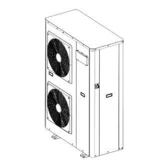
Page 6: System Layout
GENERAL INFORMATION System layout Hydronic module Discharge valve Fan protection grille 10 System filling Front service panel Mesh filter 18 Brazed plate heat exchanger Control panel 12 Electric fan 19 Air vent valve Lateral service panel 13 Compressor 20 Electrical panel Main disconnecting switch 14 Refrigerant safety valve 21 Cycle reversal valve... -
Page 7: Technical Specifications
GENERAL INFORMATION Technical specifications Model 017 TE 022 TE Cooling performance [a35 / W7] Rated Capacity 14,90 18,60 3,00 3,10 kW/kW Cooling performance [a35 / W18] Rated Capacity 20,20 25,80 3,80 kW/kW ESEER 4,01 3,85 kW/kW Eurovent Class Heating performance [a7 / W55] Rated Capacity 15,20 21,10... -
Page 8: Yield Levels Based On The Climatic Zone
GENERAL INFORMATION Yield levels based on the climatic zone Model 017 TE 022 TE Temperate zone - average temperature [47 / 55 °C] Seasonal energy efficiency (ns) SCOP 3,03 2,85 kW/kW Pdesignh 9,11 15,07 Annual energy consumption 6189 10869 kWh/annum Energy class Sound power level dB(A) -
Page 9: Operation Limits
GENERAL INFORMATION Operation Limits CoolING HEaTING A (°C) A (°C) B (°C) B (°C) External air temperature Water delivery temperature Water delivery temperature External air temperature Model 017 Model 021 1.10 Residual head The NexPolar unit is equipped with a circulation pump. For the system’s proper sizing, the residual head must be taken into account, as shown in the following graph. -
Page 10: Cooling Circuit And Probe Positioning
GENERAL INFORMATION 1.11 Cooling circuit and probe positioning The cooling circuit is of the heat pump type with a refrigerant gas heating it. During the summertime the cycle is reversed, and the reversal cycle. The source fluid utilized is the external air, while the thermal energy is extracted from the water, which is cooled, and is utility fluid is water, with the possible inclusion of a antifreeze liq- delivered to the external air. -
Page 11: Installation
Model 017 TE 022 TE The document envelope must be stored in a safe location. Product dimensions Additional copies can be requested from Riello S.p.A., which 1579 1579 reserves the right to charge the customer for the relative costs. 1141... -
Page 12: Place Of Installation
INSTALLATION The device must always be handled and moved in an upright could pose a potential hazard. These must be disposed of in position. accordance with the current legislation. Use a lifting bar in order to prevent the pressure exerted by the straps from damaging the unit. -
Page 13: Positioning
INSTALLATION Positioning Single installations The R NexPolar devices must: — be positioned on a level surface that’s capable of supporting their weight — be positioned on a sufficiently rigid surface that will not transmit any vibrations to the underlying or adjacent rooms It is recommended to place a rubber slab (hardness 60 shore, thick- ness 10 mm.) or properly sized anti-vibration supports between the device and its support surface. -
Page 14: Source Water Systems
INSTALLATION 2.9.2 Water flow rate — the system has been washed, cleaned of any sludge or limes- cale deposits, and deaerated, and that all the seals have been The water flow rate must be maintained constant while the device checked is in operation, and must respect the limit values indicated in the —... - Page 15 INSTALLATION System diagram for heat pump and DHW production Remote Panel or room thermostat External probe (accessory) NexPolar Riello ACI type puffer Riello 7200 HP type domestic hot water boiler 3-way DHW valve DHW integration resistor DHW probe...
- Page 16 System diagram for heat pump, DHW production and integrated boiler Boiler Remote Panel or room thermostat External probe (accessory) NexPolar Riello ACI type puffer Riello 7200 HP type domestic hot water boiler 3-way DHW valve DHW integration resistor DHW probe 10 Additional pump...
- Page 17 INSTALLATION System diagram for cascade heat pump NexPolar External probe (accessory) Temperature probe for cascade connection (accessory Only units of the same model can be connected in cascade configuration.
-
Page 18: Water Connections
INSTALLATION 2.10 Water connections Systems filled with antifreeze or other particular substances required by law require the use of water backflow preventers. The dimensions and positions of the R NexPolar unit’s water connections are shown in the following table. For the calculation of the required glycol percentage, refer to Prior to installation, it is recommended to thoroughly wash all the the table in chapter “Shutdown for extended periods”, p. -
Page 19: Connection Diagram
INSTALLATION 2.10.1 Connection diagram NexPolar Factory connections Safety valve Connections to be made by the installer Flow Switch 14 By-pass valve for protection against Brazed plate heat exchanger Discharge valve 15 freezing Heat exchanger electric heating ele- Mesh filter 16 Balancing valve ment 10 Shut-off valve Anti-vibration joints... -
Page 20: Filling And Emptying The System
INSTALLATION 2.11 Filling and emptying the system 2.11.2 Filling the system The R NexPolar heat pump unit requires a filling system. Before filling or emptying the system, set the system’s main switch and the device’s main switch to their “0” (off) positions. O F F The system’s cold filling pressure must be between 1.2 and 1.5 bar. - Page 21 INSTALLATION Before emptying the device: — set the system’s main switch to its “OFF” position, and the device’s main switch to its “0” (off) position O F F — close the water system’s shut-off devices — connect a hose to the device’s discharge, bring it to an appro- priate collection well, and open the valve Discharge valve Drain tube...
-
Page 22: Wiring Diagrams
INSTALLATION 2.12 Wiring diagrams PoWEr CIrCUIT A001 Variable speed drive KM90 Circulation pump Finned coil temperature A002 Main electronic board probe probe Control panel PMV1 Expansion valve motor Finned coil temperature Low pressure probe electronic probe Compressor PMV2 Expansion valve motor External air temperature probe Plate exchanger heating ele- electronic... - Page 23 INSTALLATION CoNTrol CIrCUIT A001 Variable speed drive KM90 Circulation pump Finned coil temperature A002 Main electronic board probe probe Control panel PMV1 Expansion valve motor Finned coil temperature Low pressure probe electronic probe Compressor PMV2 Expansion valve motor External air temperature probe Plate exchanger heating ele- electronic Refrigerant temperature probe...
-
Page 24: Electrical Connection
INSTALLATION PoSITIoN ElECTrICal CoMPoNENTS Terminal block for power Fan motor SP1F High pressure-switch connections Fan motor Transformer Terminal block for auxiliary FR90 Circulation pump thermal relay Delivery temperature probe fail- connections Compressor casing thermostat A001 Variable speed drive KM90 Circulation probe Finned coil temperature probe A002 Main electronic board PMV1 Expansion valve electronic... - Page 25 INSTALLATION Model 017 TE 022 TE Electrical characteristics Electrical 400/3/50+N+PE V/Ph/Hz+N power supply Permitted voltage 360 - 440 Maximum total 10,80 12,40 power consumption Maximum total 16,70 19,20 current consumption Power cable 5 x 4 n. x mm² Power cable H07RNF Type —...
-
Page 26: Auxiliary Connections
INSTALLATION 2.13.1 Auxiliary connections TErMINal BloCK x2 Remote control panel CCN slave unit Terminal block Polarity CCN+ CCN+ / WUI B+ RS485 Earth CCN CCN- CCN- / WUI B- DI#01 - On/Off Remote Parameter Function DI#02 - Remote Cooling/Heating DI#03 - Remote Comfort/Eco sfsw typ P501 DI#04 - Safety switch... - Page 27 INSTALLATION Typical connections for system configurations with heat pump and DHW production Dry contact In resistance Triac Relay Out 230 VAC Out 230 VAC - 5 A kW max. KM09 T> DHW-S Tmax. TB X1 External Heater Peak Boiler Electr. Power Renewable 3-way DHW valve...
- Page 28 INSTALLATION Connections for cascade heat pumps Unit: Unit: Unit: Unit: WUI(Remote) Master 01 ; #01 Slave01 ; #02 Slave02; #03 Slave03; #04 ;#116 WU I Polarity Cascade External probe probe Only units of the same model can be connected in cascade configuration.
-
Page 29: Control Panel
INSTALLATION 2.14 Control panel The control panel is the interface used by the Installer and the User to set all the operating parameters and to view the status of the com- ponents installed on the device. Based on the temperatures detected by the probes present within the device, and those installed in the hot water boiler, within the rooms, and outdoors, the electronics modulate the device’s operation, and the display shows the relative operating conditions. - Page 30 INSTALLATION Display It displays all the information necessary for the device’s proper management. Days of the week 10 Cascade operation Clock Alarm in progress Room temperature 12 Temperature indicator, alarm and message code Water temperature 13 Block settings Advanced settings 14 Home mode Heating mode 15 Setpoint...
- Page 31 INSTALLATION Display indication Description Temperature indication Room temperature Water temperature Indication of the parameter number and value Indication of the alarm code Indication that the occupation mode has been blocked by the user. In this case, the hourly program- ming is disabled. Indication that the “At home”...
-
Page 32: Commissioning And Maintenance
COMMISSIONING AND MAINTENANCE 3 COMMISSIONING AND MAINTENANCE Preparation for first commissioning The boiler’s first commissioning must be carried out by the Technical Support Service. Prior to commissioning, it is necessary to check that: — all the safety conditions have been met —... - Page 33 COMMISSIONING AND MAINTENANCE CoNTrol PaNEl oN BoarD (ParaMETEr 501: 3) Enter the password (0120) — press to select the first number — press to confirm the selection and move on to the next item — hold down the button for 2 seconds to validate the pass- word and gain access.
- Page 34 COMMISSIONING AND MAINTENANCE rEMoTE CoNTrol PaNEl (ParaMETEr 501: 2) External air probe (accessory) Remote control panel (accessory) The water temperature can be controlled using two methods: — fixed point — with temperature curves (external air probe recommended) The room temperature (1 zone) is controlled by the remote control panel.
- Page 35 COMMISSIONING AND MAINTENANCE Parametrisation depending on system configuration Hereunder you can find the parameters to be set depending on the system configuration (see chapter “Source water systems”, p. 15). Heat pump and DHW production N° operation Function Par. Name Description range Default 0 = DHW not managed...
- Page 36 COMMISSIONING AND MAINTENANCE N° operation Function Par. Name Description range Default Summer mode OAT The summer mode is set when the summer mode switch 15 ÷ 30 °C threshold is closed. The summer mode is set to "On" if the OAT is greater than Summer mode activation Summer mode the OAT threshold [P716] for at least the summer mode's...
- Page 37 COMMISSIONING AND MAINTENANCE Parametrisation for cascade connection Example of configuration of a system composed of three units (one Refer to chapter “Parameters”, p. 32. master and two slave units). — change according to the following table Preliminary operations Parameter Value to description range Default...
- Page 38 COMMISSIONING AND MAINTENANCE Changing address on Master unit and setting unit addresses The unit on which you are operating is displayed in the top left cor- ner. Master Slave 1 Slave 2 — press to select Slave unit no.1 — change according to the following table Parameter Value to Parameter...
- Page 39 COMMISSIONING AND MAINTENANCE Setting pump control on Master unit The pump control must be set before starting the cascade. Define if you want to control each pump installed in the single units or one single pump installed in the system, or if no pump is to be controlled via the control panel because another control system is in place.
- Page 40 COMMISSIONING AND MAINTENANCE Calibrations and pump controls Perform calibrations and controls on each single unit by operating on the parameters indicated in the table. activity Table Par. abbreviation Description Field Default Unit Enabling quick test Access to quick test mode 0 ÷...
-
Page 41: Initial Startup
COMMISSIONING AND MAINTENANCE Initial startup Temporary shutdown After having completed all the operations required to prepare for In order to shut down the unit for periods of brief absences: first commissioning, do the following to activate the device: — deactivate the unit using the on-board control panel only —... -
Page 42: Functions
FUNCTIONS 4 FUNCTIONS FUNZIONI Acronyms Indoor Air Temperature BPHE Brazed plate heat exchanger CHWS Chiller Water System Domestic Hot Water Electric heater stage Entering Water Temperature Fan Coil Unit Leaving Water Temperature New Hydronic Control Outdoor Air Temperature Pulse Modulating Valve Space Heating/Cooling Control Refrigerant Temperature Underfloor Cooling... - Page 43 FUNCTIONS CoolING TEMPEraTUrE CUrVES OAT (°C) — If the OAT is valid (not transmitted by the inverter, value out The temperature curve corresponds to the water setpoint for home of range, etc.), the water setpoint is equal to the current mode.
- Page 44 FUNCTIONS Temperature curve Min. oaT Max. oaT Min. water temp. Max. water temp. -7°C 20°C 20°C 38°C -5°C 20°C 20°C 33°C -9°C 20°C 20°C 45°C -8°C 20°C 40°C 50°C -5°C 20°C 40°C 55°C 0°C 20°C 40°C 60°C -20°C 20°C 22°C 42°C -20°C 20°C...
- Page 45 FUNCTIONS HEaTING TEMPEraTUrE CUrVES BaSED oN HoME MoDE P402 P403 Home Sleep Away OAT (°C) Fixed water setpoint If the cooling temperature curve [P586] or the heating temperature The water setpoint with direct access to the control panel (please curve [P581] are set to “-1”, the water control point will be deter- refer to the Control Panel’s user manual).
- Page 46 FUNCTIONS CUSToM TEMPEraTUrE CUrVES If the cooling temperature curve [P586] is set to “0”, the water set- The custom cooling temperature curve can be defined using the point will be calculated based on the custom cooling temperature following parameter: curve. Parameter Description Default...
- Page 47 FUNCTIONS CUSToM HEaTING TEMPEraTUrE CUrVES Default P585 P584 OAT (°C) P582 P583 — If the OAT is not valid, the water setpoint is equal to the max- — If the minimum OAT is greater than or equal to the current imum custom water temperature [P585].
- Page 48 FUNCTIONS CoolING TEMPEraTUrE CUrVES WITH oFFSETS aT THE BoTToM P413 OAT (°C) CoolING TEMPEraTUrE CUrVES WITH oFFSETS aT THE ToP P412 OAT (°C) Installation with remote user interface When the device is equipped with a remote user interface, the con- trol can be based on the air setpoint.
-
Page 49: Home Freeze Protection
FUNCTIONS CoolING Control panel Water setpoint with direct access to Water setpoint from the parameters range range occupation the control panel menu Home cooling setpoint 20 - 38°C Home cooling setpoint [P424] 20 - 38°C Home cooling setpoint [P424] + Sleep Sleep cooling setpoint 20 - 38°C 0 - 10°C... -
Page 50: Domestic Hot Water Mode
FUNCTIONS b. DHW temperature sensor or a thermostat WINTEr PoSITIoN For UNIT WITH HYDroNIC MoDUlE Based on the configuration, the DHW option can be controlled with a temperature sensor or thermostat. DHW can be produced when: — The DHW only mode is selected and there are no DHW require- ments (temperature conditions) —... -
Page 51: Pump Configuration
FUNCTIONS A delivery water temperature probe (accessory) must be in- • The compressors can be activated: stalled on-site, on the common pipes. For the probe character- Based on the configuration of the addresses: The master unit is istics and electrical connections, please refer to the instructions activated first. -
Page 52: Electric Heaters
FUNCTIONS Cooling/heating mode Boiler local remote auxiliary pump logic control control Mode off request [P573] request Enabled Disabled panel panel Based on the room Based on IAT temperature, but off N.A. N.A. N.A. vs air setpoint when DHW is enabled 4.8 Electric heaters The installer is responsible for ensuring the system’s compliance When the OAT is below the additional threshold [P604], the auxiliary... -
Page 53: Capacity Control In Night Mode
FUNCTIONS 4.11 Capacity control in night mode The night period is defined by a start time and a stop time can be set by the user. Night mode allows the user to configure the unit in such a way that it operates with specific parameters within a certain period of time, for example night period. In particu- lar, this mode allows the compressor’s frequency to be decreased during a certain time frame. -
Page 54: Maintenance
MAINTENANCE 5 MAINTENANCE Under these conditions, it is recommended to perform the follow- Standard maintenance ing maintenance interventions. Perform all the level 1 operations, and then perform the following: In order to ensure the unit’s maximum efficiency and reliability, it is Electrical checks recommended to stipulate a maintenance contract with your local —... -
Page 55: Tightening Torques For The Main Electrical Connections
MAINTENANCE — The modification of the parameters set at the factory (appli- Any faults and leaks detected must be immediately repaired. The oil cation changes), recovered from the compressor during maintenance activities con- tains refrigerant, and must be handled accordingly. —... -
Page 56: Water Heat Exchanger Maintenance
MAINTENANCE Water heat exchanger maintenance Check that: — The insulating foam is intact and remains firmly in position. — The BPHEs and the electric pipe heaters are functioning prop- erly and are correctly positioned in a secure manner. — The connections on the water side are clean and do not show any signs of leaks. -
Page 57: Alarm Codes
ALARM CODES 6 ALARM CODES The operating errors are indicated on the control panel’s display. — simultaneously hold down the buttons for 2 sec- onds to confirm the selection Fixed icon: indication that an alarm has been triggered, which caused the unit to shut off —... -
Page 58: Description Of The Alarm Signals
DESCRIPTION OF THE ALARM SIGNALS 7 DESCRIPTION OF THE ALARM SIGNALS The following tables include lists of alarm signals, together with the probable causes, the effects upon the unit, and the reset type. Current alarm reset type alarm alarm [P346] - Description Unit status assessment and measurement... - Page 59 DESCRIPTION OF THE ALARM SIGNALS Current alarm reset type alarm alarm [P346] - Description Unit status assessment and measurement [P344] [P345] automatic Cycle Comment [P349] Stoppage OR Heating Safety input Stoppage When the safety input is closed OR Cooling Stoppage This error becomes definitive Inverter Cpr stop...
- Page 60 DESCRIPTION OF THE ALARM SIGNALS Current alarm reset type alarm alarm [P346] - Description Unit status assessment and measurement [P344] [P345] automatic Cycle Comment [P349] 1. Check the cooling cycle (gas leak) Discharge This error becomes definitive 2. Electronic expansion valve temperature too Cpr stop after 4 attempts to complete of...
-
Page 61: Overview Of The Parameters
OVERVIEW OF THE PARAMETERS 8 OVERVIEW OF THE PARAMETERS This section contains an overview of all the parameters that can be Enter the password (0120) read or modified by the user. — press to select the first number The parameters are ordered as follows: —... - Page 62 OVERVIEW OF THE PARAMETERS Par. Jbus Code Description range Default Units Control panel Table 0014H freq_min Min. current compressor freq 1/10 Hz GENUNIT 0015H freq_max Max. current compressor freq 1/10 Hz GENUNIT 0016H FREQ_REQ Compr. req. Freq 1/10 Hz RO/F GENUNIT 0017H freq_cur...
- Page 63 OVERVIEW OF THE PARAMETERS Par. Jbus Code Description range Default Units Control panel Table 0044H FREQ_RED Frequency reduction mode RO/F LOADFACT [No/yes] 0045H FUNZIONAMENTO Unit operation status RO/F LOADFACT [No/yes] 0051H pmp_ovr Pump override =-1 - 16 PMP_STAT 0052H flow_err Water flow rate malfunction PMP_STAT [Normal/alarm]...
-
Page 64: Maintenance Parameters
OVERVIEW OF THE PARAMETERS Par. Jbus Code Description range Default Units Control panel Table 00D4 DHW_RUN DHW operation status RO/F DHW_STAT [No/yes] 00DD CHWSTEMP Chiller water circuit temp. 1/10°C RO/F MSL_STAT 00DE msl_cap Master/slave total capacity 0 - 100 MSL_STAT 00DF Mst_req Master request capacity... - Page 65 OVERVIEW OF THE PARAMETERS Par. Jbus Code Description range Default Units Control panel Table 0145H _FAN_LOW QT: Lower fan speed 0 - 1000 RW/F QCH_TEST 0146H _FAN_UPP QT: Upper fan speed 0 - 1000 RW/F QCH_TEST 0147H _PMV_POS QT: PMV position 0 - 1000 RW/F QCH_TEST...
-
Page 66: Setpoint Parameters
OVERVIEW OF THE PARAMETERS Setpoint parameters Par. Jbus Code description range default Units Control panel Table 0191H hwoccstp Home heating setpoint (water) 20,0 - 60,0 1/10°C WAT_STP 0192H hwunooff Sleep heating offset (water) =-10 - 0 1/10 K WAT_STP 0193H hwecooff Away heating offset (water) =-10 - 0... - Page 67 OVERVIEW OF THE PARAMETERS Par. Jbus Mnemonic Description range Default Units Control panel Table Warning: output voltage 230 Vac! 0 = not used 1 = volatile alarm (anomaly that 01FA Cust_do8 0 - 12 GEN_CONF does not block the operation) 2 = definite alarm (locked operation) 3 = standby unit...
- Page 68 OVERVIEW OF THE PARAMETERS Par. Jbus Mnemonic Description range Default Units Control panel Table 023C dt_ts Delta T sampling time 10 - 120 PMP_CONF 023D add_pmp Additional pump logic 0 - 4 PMP_CONF Heating temperature curve 0245H ht_curv =-1 - 12 CLIMCURV selection 0246H...
- Page 69 OVERVIEW OF THE PARAMETERS Par. Jbus Mnemonic Description range Default Units Control panel Table 02C2 dhw_min Minimum DHW operating time 0 - 720 DHW_CONF 02C3 dhw_max Maximum DHW operating time =-1 - 720 DHW_CONF 02C4 dhw_excp DHW exception time 45292,00 hour DHW_CONF 02C5...
- Page 72 RIELLO S.p.A. Via Ing. Pilade Riello, 7 37045 - Legnago (VR) www.riello.it Since our Company is dedicated to continuously improving its entire range of products, the aesthetic and dimensional fea- tures, technical data, equipment and accessories may be subject to change.
Need help?
Do you have a question about the NexPolar Series and is the answer not in the manual?
Questions and answers