Table of Contents
Advertisement
Quick Links
Advertisement
Table of Contents

Related Manuals for Riello NXHM A2WHPR32M/004


Summary of Contents for Riello NXHM A2WHPR32M/004
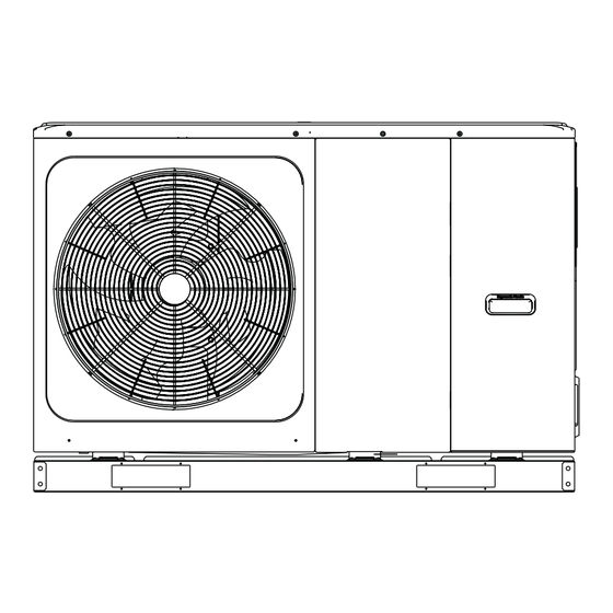
- Page 1 Riello NXHM...
- Page 2 Gamma/Range Descrizione Codice Descrizione Beretta Potenza Description Code Beretta description Power size A2WHPR32M/004 20191950 HYDRO UNIT M 004 A2WHPR32M/006 20191951 HYDRO UNIT M 006 A2WHPR32M/008 20191952 HYDRO UNIT M 008 A2WHPR32M/010 20191953 HYDRO UNIT M 010 10kW A2WHPR32M/012 20191954 HYDRO UNIT M 012 12kW A2WHPR32M/014 20191956...
-
Page 3: Table Of Contents
SAFETY PRECAUTIONS 2 GENERAL INTRODUCTION 3 ACCESSORIES 4 BEFORE INSTALLATION 5 IMPORTANT INFORMATION FOR THE REFRIGERANT 84 6 INSTALLATION SITE 6.1 Selecting a location in cold climates 6.2 Selecting a location in hot climates 7 INSTALLATION PRECAUTIONS 7.1 Dimensions 7.2 Installation requirements 7.3 Drain hole position 7.4 Servicing space requirements 8 TYPICAL APPLICATIONS... - Page 4 4/6 kW 8/10/12/14/16 kW Internal layout:12~16kW(3-phase) for example 4/6 kW Electric Control System Terminal Block Hydraulic System Refrigerant System 8/10/12/14/16 kW Please remove the hollow plate after installation. Remove the transportation support 12/14/16 kW NOTE Pictures in this manual are for reference only, please refer to the actual product. Unit 1-phase 3-phase...
-
Page 5: Safety Precautions
1 SAFETY PRECAUTIONS The precautions listed here are divided into the following types. They are quite important, so be sure to follow them carefully. Meanings of DANGER, WARNING, CAUTION and NOTE symbols. INFORMATION make sure to get All the activities described in this manual must be carried out by a licensed technician. Be sure to wear adequate personal protection equipment such as gloves and safety glasses while installing the unit or carrying out maintenance activities. - Page 6 T1S2 Hydraulic module refrigerant liquid side temperature Hydraulic module refrigerant gas side temperature Tank temperature Tw_out Plate heat exchanger outlet temperature Tw_in Plate heat exchanger inlet temperature Zone 2 outlet temperature Outdoor environment temperature PUMP I Built-in water pump in hydraulic module PUMP O External water pump for single-zone system Zone water pump for dual-zone system...
- Page 7 Do not touch the refrigerant pipes during and immediately after operation as the refrigerant pipes may be hot or cold, depending on the sible if you touch the refrigerant pipes. To avoid injury, give the pipes time to return to normal temperature or, if you must touch them,be sure to wear protective gloves.
-
Page 8: General Introduction
2 GENERAL INTRODUCTION These units are used for both heating and cooling applications and domestic hot water tanks.They can be combined with fan coil A wired controller is supplied with the unit . If you add an optional backup heater unit, the backup heater can increase the heating capacity during cold outdoor temperature. The backup heater also serves as a backup in case of malfunctioning and for frozen protection of the outside water piping during winter time. -
Page 9: Accessories
3 ACCESSORIES Accessories supplied with the unit Installation Fittings Name Shape manual Wired controller Operation range by heat pump with possible limitation and protection. Thermistor for domestic hot water tank or Drain hose Energy label Tighten belt for customer wiring use Network adapting wire Extension wire for Tbt1 Extension wire for TW2... -
Page 10: Important Information For The Refrigerant
CAUTION 5 IMPORTANT INFORMATION FOR THE REFRIGERANT the unit. Do not use the grips in the fan grills to avoid damage. The unit is top heavy! Prevent the unit from falling due to im- air. Refrigerant type: R32; Volume of GWP: 675. proper inclination during handling. -
Page 11: Selecting A Location In Cold Climates
Do not install the unit in places often used as a work space. Prepare a water drainage channel around the foundation, to drain waste water from around the unit. dust is created, the unit must be covered. If water does not easily drain from the unit, mount the unit on a should be about 100 mm. -
Page 12: Installation Precautions
7 INSTALLATION PRECAUTIONS 7.1 Dimensions 8/10/12/14/16 kW (unit: mm) 4/6 kW (unit: mm) Model 4/6kW 1295 8/10/12/14/16kW 1385 Model R1" R1" R5/4" 7.2 Installation requirements Check the strength and level of the installation ground so that the unit may not cause any vibrations or noise during its operation. Screw in the foundation bolts until their length is 20 mm from the foundation surface. -
Page 13: Drain Hole Position
7.3 Drain hole position Drain hole Drain hole 4/6 kW This drain hole is covered by rubber plug. If the smaller drain hole can not meet the drainage requirements, bigger drain hole can be used at the same time. 8/10/12/14/16 kW NOTE It's necessary to install an electrical heating belt if water can't drain out in cold weather, even the bigger drain hole has opened. -
Page 14: Typical Applications
8 TYPICAL APPLICATIONS The application examples given below are for illustration only. 8.1 Application 1 Indoor Outdoor FHL1 FHL2 FHLn 11.2 Modbus 11.1 11.3 Code Code Main unit TBH: Domestic hot water tank booster heater User interface 11.1 11.2 Coil 1 , heat exchanger for heat pump 11.3 Coil 2 , heat exchanger for Solar energy Automatic air purge valve... - Page 15 Space heating The ON/OFF signal and operation mode and temperature setting are set on the user interface. PUMP O keeps running as long as the unit is ON for space heating, SV1 keeps OFF. Domestic water heating for domestic water heating, SV1 keeps ON. b.
-
Page 16: Application
8.2 Application 2 ROOM THERMOSTAT Control for Space heating or cooling need to be set on the user interface. It can be set in three ways: MODE SET/ONE ZONE/DOUBLE ZONE. The monobloc can be connected to a high voltage room thermostat and a low voltage room thermostat. - Page 17 8.2.2 Mode set control Indoor Outdoor FCU1 FCU2 FCUn FHL1 FHL2 FHLn Code Code Main unit Collector/distributor User interface Automatic air purge valve Drainage valve RT 1..7 Low voltage room thermostat High voltage room thermostat 1…n 1...n Space heating Cooling or heating mode is set via the room thermostat, water tempe- rature is set on the user interface.
- Page 18 8.2.3 Indoor Outdoor RAD.1 ZONE1 RAD.2 RAD.n ZONE2 23.1 23.2 Modbus FHL1 FHL2 FHLn Code Code Main unit User interface Automatic air purge valve 23.1 Drainage valve 23.2 RT 1…7 FHL 1…n RAD. 1...n Space heating Zone1 can operate in cooling mode or heating mode, while zone 2 can only operate in heating mode while installation for all thermostats in zone1, only "HL"...
- Page 19 Code Code Code T5:Domestic water tank tempera- Master unit 1.2... n Slave unit 23 .1 PUMP C:Zone2 circulation pump User interface 23 .2 TBH : Domestic hot water tank 11.1 booster heater Coin 1,heat exchanger far heat Automatic air purge valve 11.2 pump Coin 2,heat exchanger far solar...
-
Page 20: Cascade System
b. Master unit operates in heating mode. When iniet water temperature is too low, or while ambient temperature is too low, the target leaving water temperature is too high, AHS will be turned on automatically. if T5 is too low or when ambient temperature is too low, target T5 temperature is too high, AHS will be turned on automatically. rates in DHW mode, AHS can't be turned on by closing M1M2. -
Page 21: Main Components
WARNING removing door 1 and door 2. Parts inside the unit may be hot. 9.2 Main components 9.2.1 4/6 kW 8~16 kW Code Explanation Automatic air purge valve Remaining air in the water circuit will be automatically removed from the water circuit. Expansion vessel Balances water system pressure. - Page 22 Note:The picture is for reference only, please refer to the actual product. Inverter module control board(PCB A) Main control board Main control board of hydraulic module of heat pump sysem(PCB B) 4/6kW Inverter module control board (PCB A) Main control board Main control board of hydraulic module of heat pump sysem(PCB B) 8/10kW...
- Page 23 Main control board of hydraulic module Inverter module control board(PCB A) Main control board of heat pump sysem(PCB B) 12/14/16kW(1-phase) Main control board of hydraulic module Inverter module control board(PCB A) Main control board of heat pump sysem(PCB B) Filter board(PCB C)(at back of the PCB B,only for 3 phase unit) 12/14/16kW(3-phase)
- Page 24 9.3.1 CN24 CN21 CN28 CN16 CN32 CN13 CN15 CN29 CN18 CN25 CN42 CN40 DIS1 CN31 CN41 CN22 CN35 CN36 CN17 26 27 14 15 CN11 CN30 Order Port Code CN21 Power Port for power supply Rotary dip switch DIS1 Digital display Port for ground CN28 PUMP...
- Page 25 Input port for solar energy 3 4 15 Port for room thermostat 5 6 16 7 8 17 9 21 Port for zone2 pump CN11 10 22 Port for outside circulation pump 11 23 Port for solar energy pump 12 24 Port for DHW pipe pump 13 16 Control port for tank booster heater...
- Page 26 9.3.2 1-phase for 4-16kW units Remarks: for 4-6kw, two capacitors Code Compressor connection port U Compressor connection port V Compressor connection port W CN20 Code CN19 Compressor connection port U Compressor connection port V Compressor connection port W CN20 CN32 CN502 CN23 CN501...
- Page 27 CN10 CN27 CN11 CN22 CN24 CN17 CN26 CN28 CN13 CN55 CN18 CN14 CN29 CN7 CN5 CN6 CN16 CN19 CN21 CN33 CN2 CN30 CN36 CN37 CN38 CN20 26 25 Code 1 Code 1 Port for communication with hydro-box control board Port for outdoor ambient temp. sensor and condenser temp.
- Page 28 9.3.3 3-phase for 12/14/16 kW units CN16 CN22 CN15 CN23 CN17 CN18 CN20 CN19 Code Code...
- Page 29 CN41 CN26 CN24 CN36 CN21 CN18 CN31 CN29 CN10 CN35 CN11 CN28 CN20 CN37 CN27 V i n CN22 CN30 CN38 CN53 CN109 Code Code Port for outdoor ambient temp. sensor and condenser Port for communication with hydro-box control board...
- Page 30 CN204 CN205 CN206 CN30 CN213 CN214 CN202 CN211 CN203 CN200 CN201 CN212 Code Code...
-
Page 31: Water Piping
9.4 Water piping All piping lengths and distances have been taken into consideration. Requirements The maximum allowed thermistor cable length is 20m. This is the maximum allowable distance between the domestic hot water tank and the NOTE If water is not removed from the system in freezing weather when unit is not used, the frozen water may damage the water circle parts. 9.4.1 Check the water circuit The unit is equipped with a water inlet and water outlet for connection to a water circuit. -
Page 32: Water Circuit Connection
Before continuing installation of the unit, check the following: Always use materials that are compatible with the water used in the system and with the materials used in the unit. Drain taps must be provided at all low points of the system to permit complete drainage of the circuit during maintenance. Air vents must be provided at all high points of the system. -
Page 33: Filling Water
When using non-copper metallic piping, be sure to insulate two kind of materials from each other to prevent galvanic corrosion. For copper is a soft material, use appropriate tools for connecting the water circuit. Inappropriate tools will cause damage to the pipes. -
Page 34: Water Piping Insulation
Fill with water pressure of approximately 2.0 bar. Remove air in the circuit as much as possible using the air purge valves. do so may cause electrical shock. Air in the water circuit could lead to malfunction of the backup Be sure to install the required fuses or circuit breakers. - Page 35 9.7.2 Wiring overview P _c P _o AHS1 AHS2 1OFF 2OFF DFT2 IBH1 DFT1 3OFF CN11 CN30 25 T Code Code Main unit S V 1:3-way valve for domestic hot water tan- User interface Booster heater Contactor Power supply Item Description AC/DC Maximum running current...
- Page 36 NOTE Please use H07RN-F for the power wire, all the cable are connect to high voltage except for thermistor cable and cable for user interface. Equipment must be grounded. All high-voltage external load, if it is metal or a grounded port, must be grounded. All external load current is needed less than 0.2A, if the single load current is greater than 0.2A, the load must be controlled through AC contactor.
- Page 37 Field wiring guidelines WARNING removing the switch box service panel. Fix all cables using cable ties. A dedicated power circuit is required for the backup heater. Lay out the electrical wiring so that the front cover does not rise up when doing wiring work and attach the front cover securely. 9.7.3 Use a round crimp-style terminal for connection to the power supply terminal board.
- Page 38 1-phase 4-16kW standard and 3-phase 12-16kW standard Outdoor Unit Power Current Compressor 220-240 11,50 0,10 0,50 220-240 13,50 0,10 0,50 220-240 14,50 0.17 1,50 10kW 220-240 15,50 0.17 1,50 12kW 220-240 23,50 0,17 1,50 14kW 220-240 24,50 0,17 1,50 16kW 220-240 25,50 0,17...
- Page 39 Slave unit Master unit Please use the shielded wire, and the shield layer must be grounded. H1 H2 H1 H2 H1 H2 ..Master unit Slave unit 1 Slave unit 2 Slave unit x Only the last IDU requires adding the network adapting wire at H1 and H2.
- Page 40 If circular wiring terminal with the insulation casing cannot be used, please make sure that: If circular wiring terminal with the insulation casing cannot be used, please make sure that: : Copper wire Circular wiring terminal Proper power wiring connections Insulation tube Power cord Figure 9.1...
- Page 41 CODE PRINT CONNECT TO CODE PRINT CONNECT TO Solar energy input signal Wired controller Room thermostat input CN30 1OFF Outdoor unit Cascade connected heat pump 2OFF PUMP C CODE PRINT CONNECT TO CN11 PUMP O Outside circulation pump Compressor run /zone1 pump DFT2 Defrost run...
- Page 42 25 26 1 2 3 4 5 25 26 27 28 1 2 3 4 5 29 30 31 32 6 7 8 9 10 29 30 31 32 6 7 8 9 10 CN11 CN30 CN11 CN30 Power supply 7 5 3 1 8 6 4 Contactor...
- Page 43 25 26 27 28 1 2 3 4 5 25 26 27 28 29 30 31 32 1 2 3 4 5 6 7 8 9 10 29 30 31 32 CN11 6 7 8 9 10 CN30 CN11 CN30 Power supply 7 5 3 1 Method A...
- Page 44 A.1 When unit detect voltage is 230VAC between CL and L1 ,the unit operates in the cooling mode. CN24 CN21 CN28 A.2 When unit detect voltage is 230VAC between HL and L1, the unit CN16 CN32 CN13 operates in the heating mode. CN15 CL-L1, HL CN29...
- Page 45 Power supply of machine and room thermostat must be con- Voltage 220-240VAC nected to the same Neutral Line . When ROOM THERMOSTAT is not set to NON, the indoor tem- 0.75 perature sensor Ta can’t be set to valid. Control port signal type Type 2 Zone 2 can only operate in heating mode, When cooling mode is set on user interface and zone1 is OFF,“CL”...
- Page 46 Voltage 220-240VAC 0.75 Control port signal type Type 2 a) Procedure Connect the cable to the appropriate terminals as shown in the picture. Fix the cable with cable ties to the cable tie mountings to ensure stress relief 10)For smart grid: The unit has smart grid function, there are two ports on PCB to connect SG signal and EVU signal as following: CN24...
-
Page 47: Start-Up And Configuration
10 START-UP AND CONFIGURATION It is important that all information in thi 10.1 DIP switch settings overview 10.1.1 Function setting ON= 1 OFF=0 ON= 1 OFF=0 ON= 1 OFF=0 10.2 During initial start-up and when water temperature is low, it is important that the water is heated gradually. Failure to do so may result in concrete Refer to 10.5.12 "SPECIAL FUNCTION"... - Page 48 Mounting: Check that the unit is properly mounted, to avoid abnormal noises and vibrations when starting up the unit. Damaged equipment: Check the inside of the unit for damaged components or squeezed pipes. Refrigerant leak: Check the inside of the unit for refrigerant leakage. If there is a refrigerant leak, call your local dealer. Power supply voltage: Check the power supply voltage on the local supply panel.
-
Page 49: Field Settings
10.5 Field settings grammable through “FOR SERVICEMAN” in user interface. Powering on the unit When power on the unit, "1%~99%" is displayed on the user interface during initialization. During this process the user inter- face cannot be operated. Procedure NOTE are in °C. - Page 50 10.5.2 COOL MODE SETTING FOR SERVICEMAN Go to MENU> FOR SERVICEMAN> 2.COOL MODE SETTING. 7. OTHER HEATING SOURCE 8. HOLIDAY AWAY MODE SETTING The following pages will be displayed: 9. SERVICE CALL SETTING 10. RESTORE FACTORY SETTINGS 2 COOL MODE SETTING 11.
-
Page 51: Room Thermostat
10.5.5 TEMP. TYPE SETTING About TEMP. TYPE SETTING temperature or room temperature is used control the ON/OFF of the heat pump. When ROOM TEMP. is enabled, the target water temperature will be calculated from climate-related curves. Addition page (zone 2) Homepage (zone 1) How to enter the TEMP. -
Page 52: Holiday Away Setting
10.5.8 HOLIDAY AWAY SETTING 10 RESTORE FACTORY SETTINGS The HOLIDAY AWAY SETTING is used to set the outlet water tempe- Please wait… rature to prevent freezing when away for holiday. Go to MENU> FOR SERVICEMAN> 8.HOLIDAY AWAY 8 HOLIDAY AWAY SETTING 8.1 T1S_H.A._H 20°C 8.2 T5S_H.A._DHW... -
Page 53: Special Function
ON/OFF. For example, when 3-way valve is selected and ON/OFF is pressed, if the 3-way valve is open/close, then the operation of 3-way 11 TEST RUN valve is normal, and so are other components. Test run is on. Heat mode is on. CAUTION Leaving water temperature is 15°C. - Page 54 12 SPECIAL FUNCTION picture below: Active the settings and active the “SPECIAL FUNCTION”? T1s+dT1s Pump CONFIRM Compressor 12 SPECIAL FUNCTION 12.1 PREHEATING FOR FLOOR t_interval_H 12.2 FLOOR DRYING UP t_firstFH will be displayed: 12.2 FLOOR DRYING UP ENTER WARM UP TIME(t_DRYUP) days KEEP TIME(t_HIGHPEAK) 5 days...
-
Page 55: Auto Restart
15 INPUT DEFINE 15.1 ON/OFF(M1M2) REMOTE 15.2 SMART GRID T_DRYPEAK 15.3 T1b(Tw2) 15.4 Tbt1 15.5 Tbt2 ADJUST 15 INPUT DEFINE t_DRYUP t_HIGHPEAK t_DRYD 15.6 Ta 15.7 SOLAR INPUT 10.5.13 AUTO RESTART 15.8 F-PIPE LENGTH <10m 15.9 dTbt2 12°C The AUTO RESTART function is used to select whether the unit reap- plies the user interface settings at the time when 15.10 RT/Ta_PCB power returns after a power supply failure. -
Page 56: Setting Parameters
10.5.18 SETTING PARAMETERS The parameters related to this chapter are shown in the table below. O r d e r Setting Code State Default Minimum Maximum Unit number interval °C °C °C °C 1.10 1.11 °C 1.12 °C 1.13 1.14 °C 1.15 1.16... -
Page 57: Double Zone
DOUBLE ZONE °C °C °C °C °C 7.10 °C °C 12.1 °C 12.3 12.4 12.5 12.6 12.7 °C 12.8 1/30 12.9 1/1/2000 31/12/2099 1/1/2001 date 13.1 13.2 MODE 14.1 15.1 ON/OFFM1 M2 15.2 15.3 15.4 15.5 15.6 15.7 15.8 15.9 °C 15.10 16.1... -
Page 58: Maintenance And Service
11 TEST RUN AND FINAL CHECKS The installer is obliged to verify correct operation of unit after installation. local dealer. 11.1 Final checks Pressure relief valve hose Check that the pressure relief valve hose is positioned appro- Before switching on the unit, read following recommenda- tions: priately to drain the water. - Page 59 NOTE For problems related to the optional solar kit for domestic water heating, refer to the troubleshooting in the Installation and owner's manual for that kit. 13.2 POSSIBLE CAUSES CORRECTIVE ACTION Check the parameters.T4HMAX,T4HMIN in heat mode. The temperature setting is not correct T4CMAX,T4CMIN in cool mode.T4DHWMAX,T4DHWMIN in DHW mode.
- Page 60 POSSIBLE CAUSES CORRECTIVE ACTION see "10.5 Field settings" Check whether or not the thermal protector of the backup he- Backup heater operation is not activated. Check if booster heater is running, the backup heater and booster heater can’t operate simultaneously. Too much heat pump capacity is used for heating domestic hot appropriately: •...
-
Page 61: Operation Parameters
13.3 Operation parameters This menu is for installer or service engineer reviewing the operation parameters. At home page, go to ''MENU''>''OPERATION PARAMETER''. "#00" to "#01", "#02" etc. accordingly OPERATION PARAMETER OPERATION PARAMETER OPERATION PARAMETER GAS BOILER ONLINE UNITS NUMBER PUMP-O T1 LEAVING WATER TEMP. -
Page 62: Error Codes
13.4 Error codes and corrective actions can be found in the table below. Reset the safety by turning the unit OFF and back ON. In case this procedure for resetting the safety is not successfull, contact your local dealer. ERROR MALFUNCTION OR PROTECTION FAILURE CAUSE AND CORRECTIVE ACTION CODE... - Page 63 Check the resistance of the sensor The T2 sensor connector is loosen. Reconnect it The T2 sensor connector is wet or there is water inside, make the connector dry. Add waterproof insulation The T2 sensor failure, change with a new sensor. 1.
- Page 64 Phase loss or neutral wire and live wire 1.Check the power supply cables should be conneted stable,aviod phase loss. 2.Check whether the sequence of neutral wire and live wire are connected reversely 1. The T3 sensor connector is loosen. Reconnect it. 2.
- Page 65 1. System is lack of refrigerant volume. Charge the refrigerant in right volume. 2. When at heating mode or DHW mode, the outdoor heating exchanger is dirty or something is block on the surface. Clean the outdoor heating exchanger or remove the obstruction.
-
Page 66: Technical Specifications
14 TECHNICAL SPECIFICATIONS 14.1 General Model 1-phase 1-phase 1-phase 3-phase 4/6 kW 8/10 kW 12/14/16 kW 12/14/16 kW Nominal capacity Refer to the Technical Data Dimensions HxWxD 792×1295×429mm 945×1385×526mm 945×1385×526mm 945×1385×526mm Net weight 98kg 121kg 144kg 160kg Gross weight 121kg 148kg 170kg 188kg... -
Page 67: Information Servicing
15 INFORMATION SERVICING Checks to the area For repair to the refrigerating system, the following precautions shall be complied with prior to conducting work on the system. Work procedure is being performed. General work area Checking for presence of refrigerant The area shall be checked with an appropriate refrigerant detector prior to and during work, to ensure the technician is aware of potentially adequately sealed or intrinsically safe. - Page 68 to be isolated prior to working on them. Do not apply any permanent inductive or capacitance loads to the circuit without ensuring that this will not exceed the permissible voltage and current permitted for the equipment in use. Intrinscially safe components are the only types that can be worked on while live in the presence of Other parts may result in the ignition of refrigerant in the atmosphere from a leak.
- Page 69 Mechanical handling equipment is available, if required, for handling refrigerant cylinders. All personal protective equipment is available and being used correctly. The recovery process is supervised at all times by a competent person. Recovery equipment and cylinders conform to the appropriate standards. Equipment shall be labelled stating that it has been de-commissioned and emptied of refrigerant.
- Page 70 item Description item Description Compressor 4-Way valve Gas-liquid separator Water outlet temperature sensor Air side heat exchanger Water lnlet temperature sensor Electronic expansion valve Automatic air purge valve Single-way electromagnetic valve Expansion vessel Strainer Circulating pump Pressure relief valve Flow switch High Pressure Switch Discharge gas sensor Low Pressure Switch...
- Page 71 CHECK FORCE_COOL...
- Page 72 CHECK FORCE_COOL...
- Page 75 Via Risorgimento, 23 A 23900 - Lecco www.berettaclima.it Poiché l’Azienda è costantemente impegnata nel continuo perfezionamento di tutta la sua produzione, le caratteristiche estetiche e dimensionali, i dati tecnici, gli equipaggiamenti e gli accessori, possono essere soggetti a variazione. In order to improve its products, our company reserves the right to modify the characteristics and information contained in this manual at any time and without prior notice.
Need help?
Do you have a question about the NXHM A2WHPR32M/004 and is the answer not in the manual?
Questions and answers