Vega VEGABAR 86 Operating Instructions Manual
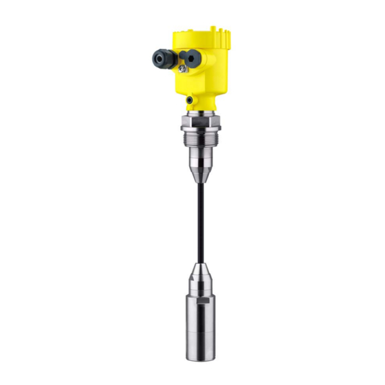
Suspension pressure transmitter with
ceramic measuring cell, 4...20 ma
Hide thumbs
Also See for VEGABAR 86:
- Operating instructions manual (92 pages) ,
- Quick setup manual (24 pages) ,
- Operating instructions manual (84 pages)

Related Manuals for Vega VEGABAR 86


Summary of Contents for Vega VEGABAR 86
- Page 1 Operating Instructions Suspension pressure transmitter with ceramic measuring cell VEGABAR 86 4 … 20 mA Document ID: 45506...
-
Page 2: Table Of Contents
Parameter adjustment ....................40 Saving the parameter adjustment data ................41 Set up with other systems DD adjustment programs ....................42 Field Communicator 375, 475 ..................42 Diagnosis, asset management and service Maintenance ........................43 VEGABAR 86 • 4 … 20 mA... - Page 3 11.2 Dimensions ........................63 Safety instructions for Ex areas Please note the Ex-specific safety information for installation and op- eration in Ex areas. These safety instructions are part of the operating instructions manual and come with the Ex-approved instruments. Editing status: 2013-09-25 VEGABAR 86 • 4 … 20 mA...
-
Page 4: About This Document
This arrow indicates a single action. Sequence of actions Numbers set in front indicate successive steps in a procedure. Battery disposal This symbol indicates special information about the disposal of bat- teries and accumulators. VEGABAR 86 • 4 … 20 mA... -
Page 5: For Your Safety
During work on and with the device the required personal protective equipment must always be worn. Appropriate use Model VEGABAR 86 is a pressure transmitter for level and gauge measurement. You can find detailed information on the application range in chapter "Product description". Operational reliability is ensured only if the instrument is properly used according to the specifications in the operating instructions manual as well as possible supplementary instructions. -
Page 6: Measuring Range - Permissible Process Pressure
That is why we have introduced an environment management system with the goal of continuously improving company environmental pro- tection. The environment management system is certified according to DIN EN ISO 14001. Please help us fulfill this obligation by observing the environmental instructions in this manual: • Chapter "Packaging, transport and storage" • Chapter "Disposal" VEGABAR 86 • 4 … 20 mA... -
Page 7: Product Description
Go to www.vega.com, "VEGA Tools" and "Serial number search". As an alternative, you can find the data via your Smartphone: • Download the smartphone app "VEGA Tools" from the "Apple App Store" or the "Google Play Store" • Scan the Data Matrix code on the type label of the instrument or •... -
Page 8: Principle Of Operation
The VEGABAR 86 is suitable for the measurement of the following process variables: • Level Fig. 2: Level measurement with VEGABAR 86 Electronic differential In combination with a slave sensor, VEGABAR 86 is also suitable for pressure electronic differential pressure measurement. You can find detailed information in the operating instructions of the respective slave sensor. Application area The VEGABAR 86 is a suspension pressure transmitter for level measurement in wells, basins and open vessels. Its great flexibility... - Page 9 Fig. 3: Front-flush installation of the CERTEC measuring cell with double seal ® Housing, transmitter Measuring cell Lateral seal for measuring cell Additional, front seal for measuring cell Diaphragm VEGABAR 86 • 4 … 20 mA...
-
Page 10: Packaging, Transport And Storage
You can find further information in the operating instructions "Interface adapter VEGACONNECT" (Document-ID 32628). VEGADIS 62 VEGADIS 62 is suitable for measured value indication and adjustment of sensors with HART protocol. It is looped into the 4 … 20 mA/HART signal cable. VEGABAR 86 • 4 … 20 mA... - Page 11 "Welded socket VEGABAR series 80" (Document-ID 45082). Electronics module The electronics module VEGABAR series 80 is a replacement part for pressure transmitters of VEGABAR series 80. There is a different version available for each type of signal output. You can find further information in the operating instructions "Elec- tronics module VEGABAR series 80" (Document-ID 45054). VEGABAR 86 • 4 … 20 mA...
-
Page 12: Mounting
Higher process temperatures often mean also higher ambient temperatures. Make sure that the upper temperature limits stated in chapter "Technical data" for the environment of the electronics hous- ing and connection cable are not exceeded. VEGABAR 86 • 4 … 20 mA... -
Page 13: Ventilation And Pressure Compensation
The following paragraphs describe how the filter element is arranged in the different instrument versions. Instruments in non-Ex The filter element is mounted into the electronics housing. It has the and Ex-ia version following functions: • Ventilation electronics housing • Atmospheric pressure compensation (with relative pressure meas- uring ranges) VEGABAR 86 • 4 … 20 mA... -
Page 14: Level Measurement
Double chamber housing, aluminium, stainless steel precision casting Rotatable metal ring Filter element Instruments with absolute pressure have a blind plug mounted instead of the filter element. Level measurement Keep the following instructions in mind for the measurement setup: Measurement setup VEGABAR 86 • 4 … 20 mA... -
Page 15: External Housing
Fig. 8: Arrangement measurement loop, external housing Vessel Sensor Connection cable sensor - external housing External housing Signal cable 1. Mark the holes according to the following drilling template Mounting 2. Fasten wall mounting plate with 4 screws VEGABAR 86 • 4 … 20 mA... - Page 16 4 Mounting 90 mm (3.54") 70 mm (2.76") 8 mm (0.12") (0.32") Fig. 9: Drilling template - wall mounting plate VEGABAR 86 • 4 … 20 mA...
-
Page 17: Connecting To Power Supply
(low impedance). With Ex systems it must be ensured that the grounding corresponds to the installation regulations. In electroplating and CCP systems (cathodic corrosion protection) it must be taken into account that significant potential differences exist. VEGABAR 86 • 4 … 20 mA... -
Page 18: Connecting
5. Insert the cable into the sensor through the cable entry Fig. 10: Connection steps 5 and 6 - Single chamber housing 6. Insert the wire ends into the terminals according to the wiring plan VEGABAR 86 • 4 … 20 mA... -
Page 19: Single Chamber Housing
Ground terminal for connection of the cable screen Housing IP 66/IP 68 (1 bar) Wire assignment, con- nection cable Fig. 12: Wire assignment fix-connected connection cable brown (+) and blue (-) to power supply or to the processing system Shielding VEGABAR 86 • 4 … 20 mA... -
Page 20: External Housing With Version Ip 68 (25 Bar)
5 Connecting to power supply External housing with version IP 68 (25 bar) Overview Fig. 13: VEGABAR 86 in IP 68 version 25 bar, non-Ex and axial cable outlet, external housing Electronics and connec- tion compartment for power supply 4...20mA 6 7 8 Fig. -
Page 21: Switch-On Phase
Indication of the instrument type, hardware and software version, measurement loop name on the display or PC • Indication of a status message on the display or PC • The output signal jumps to the set error current VEGABAR 86 • 4 … 20 mA... - Page 22 5 Connecting to power supply Then the actual measured value is outputted to the signal cable. The value takes already carried out settings, e.g. default setting into ac- count. VEGABAR 86 • 4 … 20 mA...
-
Page 23: Set Up With The Display And Adjustment Module
The display and adjustment module is powered by the sensor, an ad- ditional connection is not necessary. Fig. 17: Insertion of the display and adjustment module with single chamber housing into the electronics compartment VEGABAR 86 • 4 … 20 mA... -
Page 24: Adjustment System
Adjustment system Fig. 19: Display and adjustment elements LC display Adjustment keys • Key functions [OK] key: – Move to the menu overview – Confirm selected menu – Edit parameter VEGABAR 86 • 4 … 20 mA... -
Page 25: Parameter Adjustment - Quick Setup
3. Units In this menu item you determine the adjustment and temperature units of the instrument. Depending on the selected application in the menu item "Application", different adjustment units are available. VEGABAR 86 • 4 … 20 mA... -
Page 26: Parameter Adjustment - Extended Adjustment
Enter the percentage value and the corresponding value for the min. level. The quick setup is hence finished. Parameter adjustment - Extended adjustment For technically demanding measurement loops you can carry out extended settings in "Extended adjustment". Main menu The main menu is divided into five sections with the following func- Main menu tions: VEGABAR 86 • 4 … 20 mA... - Page 27 Numbers from 0 … 9 • Special characters +, -, /, - Setup - Application In this menu item you activate/deactivate the slave for electronic dif- ferential pressure and select the application. If you have connected a slave sensor, you confirm this with "Activate". VEGABAR 86 • 4 … 20 mA...
- Page 28 VEGABAR 86 can be used for process pressure and level measure- ment. Default setting is process pressure measurement. The mode can be changed in this adjustment menu. The VEGABAR 86 in conjunction with a slave sensor can be used for flow, differential pressure, density and interface measurement. The default setting is differential pressure measurement. Switchover is carried out in the adjustment menu.
- Page 29 Parameterization example VEGABAR 86 always measures pressure independently of the pro- cess variable selected in the menu item "Application". To output the selected process variable correctly, an allocation to 0 % and 100 % of the output signal must be carried out (adjustment).
- Page 30 4. Enter the pressure value corresponding to the min. level (e.g. 0 mbar). 5. Save settings with [OK] and move with [ESC] and [->] to the max. adjustment. The min. adjustment is finished. For an adjustment with filling, simply enter the actual measured value indicated at the bottom of the display. VEGABAR 86 • 4 … 20 mA...
- Page 31 They represent the correlation between the level per- centage and vessel volume. The linearization applies to the measured value indication and the current output. Caution: Note the following, if the respective sensor is used as part of an over- fill protection system according to WHG: VEGABAR 86 • 4 … 20 mA...
- Page 32 With active PIN, adjustment via PACTware/DTM as well as other systems is also blocked. You can change the PIN number under "Additional adjustments - PIN". Display - Language This menu item enables the setting of the requested national lan- guage. VEGABAR 86 • 4 … 20 mA...
- Page 33 The respective min. and max. measured value is saved in the sensor. ues, pressure The two values are displayed in the menu item "Peak values, pres- sure". In another window you can carry out a reset of the peak values separately. VEGABAR 86 • 4 … 20 mA...
- Page 34 "Setup/ Lock/release adjustment ". In delivery status, the PIN is "0000". Additional adjustments - In this menu item, you adjust the internal clock of the sensor. There is Date Time no adjustment to summer/winter time. VEGABAR 86 • 4 … 20 mA...
- Page 35 (with nominal measuring rang- es ≥1 bar) Temperature unit °C Position correc- 0.00 bar tion Adjustment Zero/Min. adjust- 0.00 bar ment 0.00 % Span/Max. adjust- Nominal measuring range in bar ment 100.00 % Damping Integration time 0.0 s VEGABAR 86 • 4 … 20 mA...
- Page 36 4 … 20 mA Additional adjustments - With this function the following device settings are copied. Copy instrument settings The following parameters or settings are saved: • All parameters of the menu "Setup" and "Display" VEGABAR 86 • 4 … 20 mA...
- Page 37 0 % and 100 %. Additional settings - Cur- In menu item"Current output, size" you determine which measured rent output 1 and 2 (size) value the current output refers to. VEGABAR 86 • 4 … 20 mA...
-
Page 38: Saving The Parameter Adjustment Data
"Display and adjustment module" in the menu item "Copy sensor data". The data remain there permanently even if the sensor power supply fails. The following data or settings for adjustment of the display and ad- justment module are saved: VEGABAR 86 • 4 … 20 mA... - Page 39 If it is necessary to exchange a sensor, the display and adjustment module is inserted into the replacement instrument and the data are likewise written into the sensor via the menu item "Copy sensor data". VEGABAR 86 • 4 … 20 mA...
-
Page 40: Setup With Pactware
Further setup steps are described in the operating instructions manu- al "DTM Collection/PACTware" attached to each DTM Collection and which can also be downloaded from the Internet. Detailed descrip- tions are available in the online help of PACTware and the DTMs. VEGABAR 86 • 4 … 20 mA... -
Page 41: Saving The Parameter Adjustment Data
The standard version is available as a download under www.vega.com/downloads and "Software". The full version is avail- able on CD from the agency serving you. Saving the parameter adjustment data We recommend documenting or saving the parameter adjustment data via PACTware. -
Page 42: Set Up With Other Systems
DD adjustment programs such as, for example, AMS™ and PDM. The files can be downloaded at www.vega.com/downloads under "Software". Field Communicator 375, 475 Device descriptions for the instrument are available as EDD for pa- rameter adjustment with the Field Communicator 375 or 475. VEGABAR 86 • 4 … 20 mA... -
Page 43: Diagnosis, Asset Management And Service
The data are read out via a PC with PACTware/DTM or the control system with EDD. Asset Management function The instrument features self-monitoring and diagnostics according to NE 107 and VDI/VDE 2650. In addition to the status messages in VEGABAR 86 • 4 … 20 mA... - Page 44 This status message is inactive by default. It can be activated by the user via PACTware/DTM or EDD. Failure The following table shows the error codes in the status message "Failure" and gives information on the reason and rectification. Keep in mind that some information is only valid with four-wire instruments. VEGABAR 86 • 4 … 20 mA...
- Page 45 – Send instrument for repair Error in the – Error in the EEPROM calibration F261 – Error during setup – Repeat setup – Error when carrying out a – Repeat reset Error in the reset configuration VEGABAR 86 • 4 … 20 mA...
- Page 46 "Maintenance" and provides information on causes as well as corrective measures. Code Cause Rectification Text mes- sage M500 – Stored delivery status is – Send instrument for repair wrong Error in the delivery sta- VEGABAR 86 • 4 … 20 mA...
-
Page 47: Rectify Faults
Error Cause Rectification 4 … 20 mA signal – Fluctuations of – Set damping according to the not stable the measured instrument via the display and variable adjustment module or PACTware/ VEGABAR 86 • 4 … 20 mA... -
Page 48: Calculation Of Total Deviation (According To Din 16086)
24 hour service hotline Should these measures not be successful, please call in urgent cases the VEGA service hotline under the phone no. +49 1805 858550. The hotline is also available outside normal working hours, seven days a week around the clock. -
Page 49: Exchange Process Assembly With Version Ip 68 (25 Bar)
You can find the specifications in chapter "Technical data". Practical example Level measurement 1500 mmWs Product temperature 40 °C, reference temperature 20 °C VEGABAR 86 with measuring range 0.2 bar Deviation < 0.1 % Calculation ΔT: ΔT = 40 °C - 20 °C = 20 K Calculation of the set Turn Down: TD = 200 mbar/147 mbar, TD = 1.4 Calculation 1. -
Page 50: Exchanging The Electronics Module
9 Diagnosis, asset management and service Fig. 24: VEGABAR 86 in IP 68 version, 25 bar and lateral cable outlet, external housing Process assembly Plug connector Cable assembly Connection cable External housing 3. Loosen the plug connector 4. Mount the new process assembly on the measuring point 5. -
Page 51: Software Update
The electronics module with serial number includes order- specific data such as factory setting, seal material etc. These are not included in the electronics module without serial number. The serial number is stated on the type label of VEGABAR 86 or on the delivery note. You can find detailed information on the electronics exchange in the booklet "Operating instructions for electronics module VEGABAR... -
Page 52: Dismounting
Pass the instrument directly on to a spe- cialised recycling company and do not use the municipal collecting points. These may be used only for privately used products according to the WEEE directive. VEGABAR 86 • 4 … 20 mA... -
Page 53: Supplement
Polycarbonate (UL-746-C listed) display and adjustment module Ground terminal 316Ti/316L Connection cable between transmitter PE, PUR and external electronics housing with IP 68 (25 bar) version Type label support on connection cable PE hard VEGABAR 86 • 4 … 20 mA... - Page 54 0 … 2.5 bar/0 … 250 kPa 50 bar/5000 kPa 0 bar abs. 0 … 10 bar/0 … 1000 kPa 90 bar/9000 kPa 0 bar abs. Values less than -1 bar cannot be set. VEGABAR 86 • 4 … 20 mA...
- Page 55 Adjusted failure current Load see load under Power supply Damping (63 % of the input variable), 0 … 999 s adjustable Indication value - DIsplay and adjustment module The indication values can be assigned individually VEGABAR 86 • 4 … 20 mA...
- Page 56 Reference conditions and actuating variables (according to DIN EN 60770-1) Reference conditions according to DIN EN 61298-1 Ʋ Temperature +15 … +25 °C (+59 … +77 °F) Ʋ Relative humidity 45 … 75 % VEGABAR 86 • 4 … 20 mA...
- Page 57 0 … 35 psig 0 … 0.4 bar/0 … 40 kPa 0 … 6 psig < {0.15 % + 0.4 x < {0.15 % + 0.6 x (0.5+0.5 x TD)} (0.5+0.5 x TD)} VEGABAR 86 • 4 … 20 mA...
- Page 58 0 … 15 psig < (0.25 % x TD)/year 0 … 2.5 bar/0 … 250 kPa 0 … 35 psig 0 … 0.4 bar/0 … 40 kPa 0 … 6 psig < (1 % x TD)/year VEGABAR 86 • 4 … 20 mA...
- Page 59 100 g, 6 ms according to EN 60068-2-27 (mechanical shock) Electromechanical data - version IP 66/IP 67 and IP 66/IP 68; 0.2 bar Options of the cable entry Ʋ Cable gland M20 x 1.5 VEGABAR 86 • 4 … 20 mA...
- Page 60 Ʋ Min. bending radius at 25 °C/77 °F 25 mm (0.985 in) Ʋ Diameter approx. 8 mm (0.315 in) Ʋ Colour Blue Cable entry/plug Depending on the version M12 x 1, according to ISO 4400, Harting, 7/8" FF. VEGABAR 86 • 4 … 20 mA...
- Page 61 12 h/24 h Time zone Ex factory Rate deviation max. 10.5 min/year Measurement electronics temerature Resolution 1 °C (1.8 °F) Accuracy ±1 °C (1.8 °F) Voltage supply Operating voltage U Ʋ Non-Ex instrument 9.6 … 35 V DC VEGABAR 86 • 4 … 20 mA...
- Page 62 IP 68 (1 bar) NEMA 4X Double chamber IP 66/IP 67 NEMA 4X IP 66/IP 68 (0.2 bar) NEMA 4X Stainless steel Transmitter for external IP 68 (25 bar) housing Overvoltage category Protection class Approvals Instruments with approvals can have different technical data depending on the version. VEGABAR 86 • 4 … 20 mA...
-
Page 63: Dimensions
11 Supplement For that reason the associated approval documents of these instruments must be carefully noted. They are part of the delivery or can be downloaded under www.vega.com and "VEGA Tools" as well as under "Downloads" and "Approvals". 11.2 Dimensions The following dimensional drawings represent only an extract of the possible versions. - Page 64 (1.64") ~ 66 mm (2.60") 110 mm x 90 mm (4.33" x 3.54") Fig. 28: VEGABAR 86, IP 68 version with external housing Lateral cable outlet Axial cable outlet Plastic version Stainless steel version Seal 2 mm (0.079 in) - only with 3A approval...
- Page 65 ø 8 mm ø 29 mm (0.32") (1.14") ø 32 mm (1.26") Fig. 29: VEGABAR 86, transmitter 32 mm with straining clamp With threaded fitting G1½ (1½ NPT) With thread G1½ (1½ NPT) with direct cable outlet Lock fitting VEGABAR 86 • 4 … 20 mA...
- Page 66 ø 44 mm ø 37 mm (1.73") (1.46") Fig. 30: VEGABAR 86, plastic versions PVDF, with threaded fitting G1½ (1½ NPT) PVDF, with thread G1½ (1½ NPT) PE coated, with thread G1½ (1½ NPT) VEGABAR 86 • 4 … 20 mA...
- Page 67 6 " 4xø0.63 " 6 " 4" 10" 1 .25" 7.87 " 8xø0.63 " 6.19 " 0.12 " Fig. 31: VEGABAR 86, flange connection Flanges according to DIN 2501 Flanges according to ANSI B16.5 VEGABAR 86 • 4 … 20 mA...
- Page 68 ø 64 mm (2.52") ø 92 mm (3.62") ø 8 mm (0.32") ø 32 mm (1.26") Fig. 32: VEGABAR 86, hygienic fittings Clamp 2" (ø64 mm) PN16 DIN 32676, ISO 2852/316L Bolting DN 50 VEGABAR 86 • 4 … 20 mA...
- Page 69 (1.58") SW 27 mm SW 41 mm (1.06") (1.61") G½ G¼ ø 22 mm (0.87 ") Fig. 33: VEGABAR 86, threaded version Thread G½ internal G¼ Thread ½NPT hole ø11 mm Thread G1 VEGABAR 86 • 4 … 20 mA...
- Page 70 Les lignes de produits VEGA sont globalement protégées par des droits de propriété intellec- tuelle. Pour plus d'informations, on pourra se référer au site www.vega.com. VEGA lineas de productos están protegidas por los derechos en el campo de la propiedad indus- trial. Para mayor información revise la pagina web www.vega.com.
- Page 71 EDD (Enhanced Device Description) 42 Electronics and connection compartment, single chamber housing 21 Error codes 44, 46 Event memory 43 Fault rectification 47 Grounding 17 Level measurement 14 Linearization 31 Maintenance 43 Measured value memory 43 Measurement setup VEGABAR 86 • 4 … 20 mA...
- Page 72 Subject to change without prior notice © VEGA Grieshaber KG, Schiltach/Germany 2013 VEGA Grieshaber KG Phone +49 7836 50-0 Am Hohenstein 113...
Need help?
Do you have a question about the VEGABAR 86 and is the answer not in the manual?
Questions and answers