Vega VEGABAR 86 Quick Setup Manual
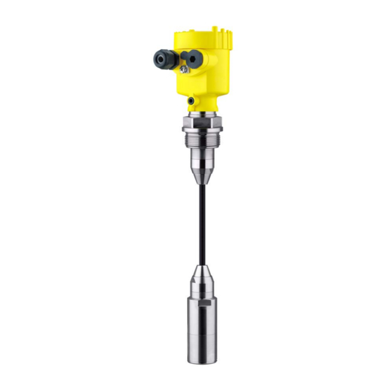
Submersible pressure transmitter with ceramic measuring cell
Hide thumbs
Also See for VEGABAR 86:
- Operating instructions manual (92 pages) ,
- Quick setup manual (24 pages) ,
- Operating instructions manual (84 pages)

Related Manuals for Vega VEGABAR 86


Summary of Contents for Vega VEGABAR 86
- Page 1 Quick setup guide Submersible pressure transmitter with ceramic measuring cell VEGABAR 86 4 … 20 mA/HART With SIL qualification Document ID: 46321...
-
Page 2: Table Of Contents
Operating Instructions Manual as well as the Safety Manual that comes with instruments with SIL qualification. These manuals are available on our homepage. Operating instructions VEGABAR 86 - 4 … 20 mA/HART: Document-ID 45041 Safety Manual VEGABAR series 80 - Two-wire 4 … 20 mA/HART with SIL qualification: Document-ID 48369 Editing status of the quick setup guide: 2022-04-20 VEGABAR 86 •... -
Page 3: For Your Safety
All operations described in this documentation must be carried out only by trained, qualified personnel authorised by the plant operator. During work on and with the device, the required personal protective equipment must always be worn. Appropriate use Model VEGABAR 86 is a pressure transmitter for level and gauge measurement. You can find detailed information about the area of application in chapter " Product description". Operational reliability is ensured only if the instrument is properly used according to the specifications in the operating instructions manual as well as possible supplementary instructions. -
Page 4: Sil Qualification According To Iec 61508
For detailed specification of the safety requirements, multiple SIL levels are specified according to safety standard IEC 61508. You can find detailed information in chapter " Functional safety (SIL)" of the operating instructions. The instrument meets the specifications of IEC 61508: 2010 (Edi- tion 2). It is qualified for single-channel operation up to SIL2. The instrument can be used homogeneously redundant up to SIL3 in multi-channel architecture with HFT 1. VEGABAR 86 • 4 … 20 mA/HART... -
Page 5: Product Description
• Test certificate (PDF) - optional Move to " www.vega.com" and enter in the search field the serial number of your instrument. Alternatively, you can access the data via your smartphone: • Download the VEGA Tools app from the " Apple App Store" or the " Google Play Store" • Scan the DataMatrix code on the type label of the instrument or • Enter the serial number manually in the app... -
Page 6: Mounting
Aluminium - single chamber Stainless steel single chamber (electropolished) Plastic double chamber Aluminium, stainless steel double chamber housing (precision casting) Filter element With the following instruments a blind plug is installed instead of the filter element: VEGABAR 86 • 4 … 20 mA/HART... - Page 7 3 Mounting • Instruments in protection IP66/IP68 (1 bar) - ventilation via capillar- ies in non-detachable cable • Instruments with absolute pressure VEGABAR 86 • 4 … 20 mA/HART...
-
Page 8: Connecting To Power Supply
6. Insert the wire ends into the terminals according to the wiring plan Note: Solid cores as well as flexible cores with wire end sleeves are insert- ed directly into the terminal openings. In case of flexible cores without end sleeves, press the terminal from above with a small screwdriver, the terminal opening is then free. When the screwdriver is released, the terminal closes again. 7. Check the hold of the wires in the terminals by lightly pulling on them 8. Connect the shielding to the internal ground terminal, connect the external ground terminal to potential equalisation VEGABAR 86 • 4 … 20 mA/HART... -
Page 9: Single Chamber Housing
Fig. 5: Connection compartment - double chamber housing Voltage supply, signal output For display and adjustment module or interface adapter For external display and adjustment unit Ground terminal for connection of the cable screening VEGABAR 86 • 4 … 20 mA/HART... -
Page 10: Set Up With The Display And Adjustment Module
3. Screw housing lid with inspection window tightly back on Disassembly is carried out in reverse order. The display and adjustment module is powered by the sensor, an ad- ditional connection is not necessary. Fig. 6: Installing the display and adjustment module in the electronics compart- ment of the single chamber housing VEGABAR 86 • 4 … 20 mA/HART... -
Page 11: Parameter Adjustment
The instrument is shipped in locked condition. To prevent unintentional or unauthorized adjustment, the instrument is protected (locked) against all parameter changes while in normal operating condition. For each parameter change you have to enter the PIN of the instru- ment. In delivery status, the PIN is "0000". Change parameters You can find a description below the respective parameter. VEGABAR 86 • 4 … 20 mA/HART... - Page 12 4. Depending on the application, carry out the adjustment e.g. in the menu items " Min. adjustment" and " Max. adjustment". Parameterization example VEGABAR 86 always measures pressure independently of the pro- cess variable selected in the menu item " Application". To output the selected process variable correctly, an allocation of the output signal to 0 % and 100 % must be carried out (adjustment).
- Page 13 3. Serial number acknowledgement Afterwards you confirm that the serial number of your instrument was carried over correctly. This is used to check device communication. 4. Verify parameters Confirm the modified values one after the other. If the described process of parameter adjustment was run through completely and correctly, the instrument will be locked and hence ready for operation. VEGABAR 86 • 4 … 20 mA/HART...
-
Page 14: Menu Overview
Last setting Display Menu item Default value Menu language No reset Displayed value 1 Pressure Displayed value 2 Ceramic measuring cell: Measuring cell temperature in °C Metallic measuring cell: Electronics temperature in °C VEGABAR 86 • 4 … 20 mA/HART... - Page 15 0 … 100 % correspond to 4 … 20 mA HART mode HART address, current output Address 00, analogue current output Special parameter (SIL) Service-Login No reset Info Menu item Parameter Device name VEGABAR 86 Instrument version Hardware and software version Factory calibration date Date Sensor characteristics Order-specific characteristics VEGABAR 86 • 4 … 20 mA/HART...
-
Page 16: Set Up With Smartphone/Tablet, Pc/Notebook Via Bluetooth
The default setting of the sensor PIN is " 0000". First of all you have to change the sensor PIN in the adjustment menu of the sensor, e.g. to " 1111": 1. Go to setup via the extended operation 2. Lock operation by changing sensor PIN 3. Enable operation again by entering the sensor PIN once more VEGABAR 86 • 4 … 20 mA/HART... -
Page 17: Connecting
Bluetooth-capable instru- ments in the area. PC/Notebook Start PACTware and the VEGA project assistant. Select the device search via Bluetooth and start the search function. The device auto- matically searches for Bluetooth-capable devices in the vicinity. - Page 18 6 Set up with smartphone/tablet, PC/notebook via Bluetooth App view Fig. 10: Example of an app view - Setup sensor adjustment VEGABAR 86 • 4 … 20 mA/HART...
-
Page 19: Supplement
< 14 V) ≤ 0.7 V (16 … 400 Hz) Ʋ for U 24 V DC (18 V < U < 35 V) ≤ 1.0 V (16 … 400 Hz) Load resistor Ʋ Calculation )/0.022 A Ʋ Example - with U = 24 V DC (24 V - 9.6 V)/0.022 A = 655 Ω IP66/IP68 (0.2 bar), only with absolute pressure. VEGABAR 86 • 4 … 20 mA/HART... - Page 20 Subject to change without prior notice © VEGA Grieshaber KG, Schiltach/Germany 2022 VEGA Grieshaber KG Am Hohenstein 113 Phone +49 7836 50-0 77761 Schiltach E-mail: info.de@vega.com...
Need help?
Do you have a question about the VEGABAR 86 and is the answer not in the manual?
Questions and answers