Vega VEGABAR 86 Operating Instructions Manual
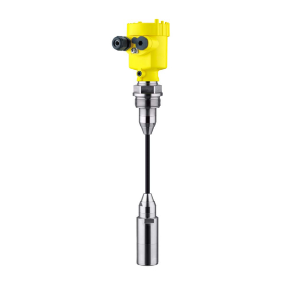
Submersible pressure transmitter with ceramic measuring cell
Hide thumbs
Also See for VEGABAR 86:
- Operating instructions manual (92 pages) ,
- Quick setup manual (24 pages) ,
- Operating instructions manual (72 pages)

Related Manuals for Vega VEGABAR 86


Summary of Contents for Vega VEGABAR 86
- Page 1 Operating Instructions Submersible pressure transmitter with ceramic measuring cell VEGABAR 86 Foundation Fieldbus Document ID: 45043...
-
Page 2: Table Of Contents
Saving the parameterisation data ................... 42 Setup with PACTware ......................43 Connect the PC ......................43 Parameter adjustment with PACTware ................43 Saving the parameterisation data ................... 44 Set up with other systems ....................45 VEGABAR 86 • Foundation Fieldbus... - Page 3 11.6 Gewerbliche Schutzrechte ..................... 79 11.7 Trademark ........................79 Safety instructions for Ex areas Take note of the Ex specific safety instructions for Ex applications. These instructions are attached as documents to each instrument with Ex approval and are part of the operating instructions. Editing status: 2021-03-31 VEGABAR 86 • Foundation Fieldbus...
-
Page 4: Zu Diesem Dokument
Verwendete Symbolik Document ID Dieses Symbol auf der Titelseite dieser Anleitung weist auf die Docu- ment ID hin. Durch Eingabe der Document ID auf www.vega.com kommen Sie zum Dokumenten-Download. Information, Hinweis, Tipp: Dieses Symbol kennzeichnet hilfreiche Zusatzinformationen und Tipps für erfolgreiches Arbeiten. -
Page 5: For Your Safety
During work on and with the device, the required personal protective equipment must always be worn. Appropriate use Model VEGABAR 86 is a pressure transmitter for level and gauge measurement. You can find detailed information about the area of application in chapter " Product description". Operational reliability is ensured only if the instrument is properly used according to the specifications in the operating instructions manual as well as possible supplementary instructions. -
Page 6: Namur Recommendations
That is why we have introduced an environment management system with the goal of continuously improving company environmental pro- tection. The environment management system is certified according to DIN EN ISO 14001. Please help us fulfil this obligation by observing the environmental instructions in this manual: • Chapter "Packaging, transport and storage" • Chapter "Disposal" VEGABAR 86 • Foundation Fieldbus... -
Page 7: Product Description
Ventilation valves, closing screws – depending on version (see chapter "Dimensions") The further scope of delivery encompasses: • Documentation – Quick setup guide VEGABAR 86 – Test certificate for pressure transmitters – Instructions for optional instrument features – Ex-specific "Safety instructions" (with Ex versions) – If necessary, further certificates... -
Page 8: Principle Of Operation
Alternatively, you can access the data via your smartphone: • Download the VEGA Tools app from the "Apple App Store" or the "Google Play Store" • Scan the DataMatrix code on the type label of the instrument or •... - Page 9 3 Product description Fig. 2: Level measurement with VEGABAR 86 Electronic differential Depending on the version, the VEGABAR 86 is also suitable for pressure electronic differential pressure measurement. For this, the instrument is combined with a Secondary Device. Fig. 3: Electronic differential pressure measurement via a Primary/Secondary combination You can find detailed information in the operating instructions of the respective Secondary Device.
- Page 10 The ambient pressure is detected through a reference sensor in the electronics and compensated. It thus has no influence on the measured value. Seal concept The following illustration shows the installation of the ceramic measur- ing cell in the sensor as well as the sealing concept. VEGABAR 86 • Foundation Fieldbus...
-
Page 11: Packaging, Transport And Storage
Technical data - Ambient conditions" • Relative humidity 20 … 85 % Lifting and carrying With instrument weights of more than 18 kg (39.68 lbs) suitable and approved equipment must be used for lifting and carrying. VEGABAR 86 • Foundation Fieldbus... -
Page 12: Accessories
USB interface of a PC. Secondary sensors Secondary sensors of VEGABAR series 80 enable in conjunction with VEGABAR 86 an electronic differential pressure measurement. VEGADIS 81 The VEGADIS 81 is an external display and adjustment unit for VEGA plics sensors. ® VEGADIS adapter The VEGADIS adapter is an accessory part for sensors with double chamber housings. -
Page 13: Mounting
Depending on the device version, tightening can cause dam- age, e. g. to the rotation mechanism of the housing. Vibrations Avoid damages on the device by lateral forces, for example by vibra- tions. It is thus recommended to fix the devices with process fitting VEGABAR 86 • Foundation Fieldbus... - Page 14 Fig. 5: Temperature ranges Process temperature Ambient temperature Depending on the transmitter, the VEGABAR 86 is supplied with a Transport and mounting protection protective cap or a transport and mounting protection. VEGABAR 86 • Foundation Fieldbus...
-
Page 15: Ventilation And Pressure Compensation
4 Mounting Fig. 6: VEGABAR 86, transport and mounting protection Transmitter Transport and mounting protection Remove this protection after mounting and before setting up the instrument. In case of slightly contaminated measured media, the transport and mounting protection can remain on the instrument as an impact pro- tection during operation. - Page 16 Instruments in protection IP66/IP68 (1 bar) - ventilation via capillar- ies in non-detachable cable • Instruments with absolute pressure → Filter element - Position Turn the metal ring in such a way that the filter element points Ex-d version downward after installation of the instrument. This provides better protection against buildup. VEGABAR 86 • Foundation Fieldbus...
- Page 17 With relative pressure measuring ranges, the ambient pressure is detected and compensated by a reference sensor in the electronics. Fig. 9: Position of the filter element - gastight leadthrough Filter element Gas-tight leadthrough VEGABAR 86 • Foundation Fieldbus...
-
Page 18: Level Measurement
• Mount the instrument so that it is protected against pressure shocks from the stirrer External housing Configuration Fig. 11: Arrangement measurement loop, external housing Sensor Connection cable sensor, external housing External housing Signal cable VEGABAR 86 • Foundation Fieldbus... -
Page 19: Connecting To The Bus System
In the case of instrument housings with self-sealing NPT threads, it is not possible to have the cable entries screwed in at the factory. The free openings for the cable glands are therefore covered with red dust protection caps as transport protection. VEGABAR 86 • Foundation Fieldbus... -
Page 20: Connecting
6. Insert the wire ends into the terminals according to the wiring plan Note: Solid cores as well as flexible cores with wire end sleeves are insert- ed directly into the terminal openings. In case of flexible cores without end sleeves, press the terminal from above with a small screwdriver, the terminal opening is then free. When the screwdriver is released, the terminal closes again. VEGABAR 86 • Foundation Fieldbus... -
Page 21: Single Chamber Housing
Simulation switch ("1" = mode for simulation release) For external display and adjustment unit Ground terminal for connection of the cable screening Double chamber housing The following illustrations apply to the non-Ex as well as to the Ex-ia version. VEGABAR 86 • Foundation Fieldbus... - Page 22 6 7 8 Fig. 15: Connection compartment - double chamber housing Voltage supply, signal output For display and adjustment module or interface adapter For external display and adjustment unit Ground terminal for connection of the cable screening VEGABAR 86 • Foundation Fieldbus...
-
Page 23: Double Chamber Housing With Vegadis-Adapter
Fig. 17: Top view of the M12 x 1 plug connector Pin 1 Pin 2 Pin 3 Pin 4 Contact pin Colour, connection ca- Terminal, electronics ble in the sensor module Pin 1 Brown Pin 2 White Pin 3 Blue Pin 4 Black VEGABAR 86 • Foundation Fieldbus... -
Page 24: Housing Ip66/Ip68 (1 Bar)
Brown (+) and blue (-) to power supply or to the processing system Shielding External housing with version IP68 (25 bar) Overview Fig. 19: VEGABAR 86 in IP68 version 25 bar, non-Ex and axial cable outlet, external housing VEGABAR 86 • Foundation Fieldbus... - Page 25 Cable gland for voltage supply Cable gland for connection cable, transmitter Terminal compartment, housing socket 1 2 3 4 Fig. 21: Connection of the process component in the housing base Yellow White Black Shielding Breather capillaries VEGABAR 86 • Foundation Fieldbus...
-
Page 26: Switch-On Phase
Indication of a status message on the display or PC Then the actual measured value is output to the signal cable. The value takes into account settings that have already been carried out, e.g. default setting. VEGABAR 86 • Foundation Fieldbus... -
Page 27: Set Up With The Display And Adjustment Module
The display and adjustment module is powered by the sensor, an ad- ditional connection is not necessary. Fig. 23: Installing the display and adjustment module in the electronics compart- ment of the single chamber housing VEGABAR 86 • Foundation Fieldbus... -
Page 28: Adjustment System
– Move to the menu overview – Confirm selected menu – Edit parameter – Save value • [->] key: – Change measured value presentation – Select list entry – Select menu items – Select editing position • [+] key: VEGABAR 86 • Foundation Fieldbus... -
Page 29: Measured Value Indication
[OK] will not be saved. Measured value indication Measured value indica- With the [->] key you can move between three different indication tion modes. In the first view, the selected measured value is displayed in large digits. In the second view, the selected measured value and a respective bargraph presentation are displayed. VEGABAR 86 • Foundation Fieldbus... -
Page 30: Parameter Adjustment - Quick Setup
[->] or [ESC] keys or automatically after 3 s Note: You can find a description of the individual steps in the quick setup guide of the sensor. You can find "Extended adjustment" in the next sub-chapter. Parameter adjustment - Extended adjustment For technically demanding measuring points, you can carry out extended settings in "Extended adjustment". VEGABAR 86 • Foundation Fieldbus... - Page 31 Application In this menu item you activate/deactivate the Secondary sensor for electronic differential pressure and select the application. VEGABAR 86 can be used for process pressure and level measure- ment. Default setting is process pressure measurement. The mode can be changed in this adjustment menu. If you have connected no Secondary sensor, you confirm this with "Deactivate".
- Page 32 20 % of the nominal measuring range, then no position correction is possible. Adjustment VEGABAR 86 always measures pressure independently of the pro- cess variable selected in the menu item "Application". To output the VEGABAR 86 • Foundation Fieldbus...
- Page 33 1. Select the menu item "Setup" with [->] and confirm with [OK]. Now select with [->] the menu item "Zero adjustment" and confirm with [OK]. 2. Edit the mbar value with [OK] and set the cursor to the requested position with [->]. VEGABAR 86 • Foundation Fieldbus...
- Page 34 [OK]. The span adjustment is finished. Min. adjustment - Level Proceed as follows: 1. Select the menu item "Setup" with [->] and confirm with [OK]. Now select with [->] the menu item "Adjustment", then "Min. adjustment" and confirm with [OK]. VEGABAR 86 • Foundation Fieldbus...
- Page 35 - and the indication or output of the volume is required. Corresponding linearization curves are preprogrammed for these vessels. They represent the correlation between the level per- centage and vessel volume. The linearization applies to the measured value indication and the current output. VEGABAR 86 • Foundation Fieldbus...
- Page 36 This menu item enables the setting of the requested national lan- guage. The following languages are available: • German • English • French • Spanish • Russian • Italian • Dutch • Portuguese • Japanese • Chinese VEGABAR 86 • Foundation Fieldbus...
- Page 37 • Polish • Czech • Turkish In delivery status, the VEGABAR 86 is set to English. Display value 1 and 2 In this menu item, you define which measured value is displayed. The default setting for the display value is "Lin. percent". Display format 1 and 2 In this menu item you define the number of decimal positions with which the measured value is displayed.
- Page 38 Date/Time In this menu item, you adjust the internal clock of the sensor. There is no adjustment for summer/winter (daylight saving) time. Reset After a reset, certain parameter adjustments made by the user are reset. VEGABAR 86 • Foundation Fieldbus...
- Page 39 The data are saved only after release. Special parameters In this menu item you gain access to the protected area where you can enter special parameters. In exceptional cases, individual parameters can be modified in order to adapt the sensor to special requirements. VEGABAR 86 • Foundation Fieldbus...
-
Page 40: Menu Overview
In this menu item, the features of the sensor such as approval, pro- cess fitting, seal, measuring range, electronics, housing and others are displayed. Menu overview The following tables show the adjustment menu of the instrument. Depending on the instrument version or application, all menu items may not be available or some may be differently assigned. VEGABAR 86 • Foundation Fieldbus... - Page 41 Pointer function temp. Temperature Actual measuring cell and electronic tem- perature Simulation Pressure, percent, current output, Process pressure linearized percent, measuring cell tem- perature, electronics temperature Additional adjustments Menu item Parameter Default value Date/Time Actual date/Actual time VEGABAR 86 • Foundation Fieldbus...
-
Page 42: Saving The Parameterisation Data
In the display and adjust- If the instrument is equipped with a display and adjustment module, ment module the parameter adjustment data can be saved therein. The procedure is described in menu item "Copy device settings". VEGABAR 86 • Foundation Fieldbus... -
Page 43: Setup With Pactware
Further setup steps are described in the operating instructions manu- al "DTM Collection/PACTware" attached to each DTM Collection and which can also be downloaded from the Internet. Detailed descrip- tions are available in the online help of PACTware and the DTMs. VEGABAR 86 • Foundation Fieldbus... -
Page 44: Saving The Parameterisation Data
The standard version is available as a download under www.vega.com/downloads and "Software". The full version is avail- able on CD from the agency serving you. Saving the parameterisation data We recommend documenting or saving the parameterisation data via PACTware. -
Page 45: Set Up With Other Systems
8 Set up with other systems Set up with other systems DD adjustment programs Device descriptions as Enhanced Device Description (EDD) are available for DD adjustment programs such as, for example, AMS™ and PDM. The files can be downloaded at www.vega.com/downloads under "Software". VEGABAR 86 • Foundation Fieldbus... -
Page 46: Diagnosis, Asset Management And Service
Event memory Up to 500 events are automatically stored with a time stamp in the sensor (non-deletable). Each entry contains date/time, event type, event description and value. Event types are for example: • Modification of a parameter VEGABAR 86 • Foundation Fieldbus... -
Page 47: Asset Management Function
This status message is inactive by default. Maintenance required: Due to external influences, the instrument function is limited. The measurement is affected, but the measured value is still valid. Plan in maintenance for the instrument because a failure is expected in the near future (e.g. due to buildup). This status message is inactive by default. VEGABAR 86 • Foundation Fieldbus... - Page 48 Repeat reset settings F264 Inconsistent settings (e.g.: dis- Modify settings Bit 10 tance, adjustment units with Installation/Setup error Modify connected sensor config- application process pressure) for uration or application selected application Invalid sensor configuration (e.g.: application electronic differential pressure with connected differen- tial pressure measuring cell) VEGABAR 86 • Foundation Fieldbus...
- Page 49 Hardware error EEPROM Exchanging the electronics Bit 17 Error in the event Send instrument for repair memory M504 Hardware defect Exchanging the electronics Bit 19 Error at a device in- Send instrument for repair terface VEGABAR 86 • Foundation Fieldbus...
-
Page 50: Rectify Faults
24 Stunden Service- Sollten diese Maßnahmen dennoch zu keinem Ergebnis führen, Hotline rufen Sie in dringenden Fällen die VEGA Service-Hotline an unter Tel. +49 1805 858550. Die Hotline steht Ihnen auch außerhalb der üblichen Geschäftszeiten an 7 Tagen in der Woche rund um die Uhr zur Verfügung. -
Page 51: Exchanging The Electronics Module
Proceed as follows when carrying out the exchange: 1. Losen the fixing screw with the hexagon key wrench 2. Carefully detach the cable assembly from the process module Fig. 31: VEGABAR 86 in IP68 version, 25 bar and lateral cable outlet, external housing Process module Plug connector... -
Page 52: Software Update
Clean the instrument and pack it damage-proof • Attach the completed form and, if need be, also a safety data sheet outside on the packaging • Ask the agency serving you to get the address for the return ship- ment. You can find the agency on our homepage. VEGABAR 86 • Foundation Fieldbus... -
Page 53: Dismount
Pass the instrument directly on to a specialised recycling company and do not use the municipal collecting points. If you have no way to dispose of the old instrument properly, please contact us concerning return and disposal. VEGABAR 86 • Foundation Fieldbus... -
Page 54: Supplement
Ʋ Inspection window housing cover Polycarbonate (UL-746-C listed), glass Ʋ Ground terminal 316L External housing - deviating materials Ʋ Housing and socket Plastic PBT (Polyester), 316L Glass with Aluminium and stainless steel precision casting housing VEGABAR 86 • Foundation Fieldbus... - Page 55 Gauge pressure 0 … +0.025 bar/0 … +2.5 kPa +5 bar/+500 kPa -0.05 bar/-5 kPa Only for 316L with 3A approval Between transmitter and external electronics housing. Data on overload capability apply for reference temperature. VEGABAR 86 • Foundation Fieldbus...
- Page 56 0 … 30 psi 360 psig 0 psi 0 … 150 psi 360 psig 0 psi 0 … 300 psi 360 psig 0 psi 0 … 900 psig 360 psig 0 psi Adjustment ranges Specifications refer to the nominal measuring range, pressure values lower than -1 bar cannot be VEGABAR 86 • Foundation Fieldbus...
- Page 57 90 % 10 % Fig. 32: Behaviour in case of sudden change of the process variable. t : dead time; t : rise time; t : jump response time Process variable Output signal Dead time ≤ 50 ms VEGABAR 86 • Foundation Fieldbus...
- Page 58 TD 1 : 1 up to 5 : 1 bility with 5 : 1 0.1 % < 0.1 % < 0.02 % x TD Influence of the product temperature Thermal change zero signal and output span Turn down (TD) is the relation nominal measuring range/adjusted span. VEGABAR 86 • Foundation Fieldbus...
- Page 59 TD 5 : 1 TD 10 : 1 TD 20 : 1 Factor FTD 1.75 10.5 Long-term stability (according to DIN 16086) Applies to the respective digital signal output (e.g. HART, Profibus PA) as well as to analogue cur- rent output 4 … 20 mA under reference conditions. Specifications refer to the set span. Turn down (TD) is the ratio nominal measuring range/set span. VEGABAR 86 • Foundation Fieldbus...
- Page 60 -20 … +80 °C (-4 … +176 °F) EPDM (A+P 70.10-02) Suspension cable FEP FKM (VP2/A) -20 … +100 °C (-4 … +212 °F) EPDM (A+P 70.10-02) FFKM (Kalrez 6375) -10 … +100 °C (+14 … +212 °F) VEGABAR 86 • Foundation Fieldbus...
- Page 61 Ʋ Stranded wire with end sleeve 0.2 … 1.5 mm² (AWG 24 … 16) Depending on the instrument version 2 g with housing version stainless steel double chamber IP66/IP68 (0.2 bar), only with absolute pressure. VEGABAR 86 • Foundation Fieldbus...
- Page 62 4 … 20 mA/HART 50 m ● – Modbus Profibus PA, Foundation Fieldbus 25 m – ● Interface to the Secondary sensor Data transmission Digital (I²C-Bus) Configuration, connection cable 4-wire, shielded Max. cable length 25 m Breather capillaries not with Ex-d version. VEGABAR 86 • Foundation Fieldbus...
- Page 63 Double chamber IP66/IP67 Type 4X IP66/IP68 (0.2 bar) Type 6P Stainless steel (electro-polished) Single chamber IP66/IP67 Type 4X IP69K Galvanic separation between electronics and metal housing parts Protection rating IP66/IP68 (0.2 bar) only in conjunction with absolute pressure. VEGABAR 86 • Foundation Fieldbus...
-
Page 64: Device Communication Foundation Fieldbus
Revisions Data DD-Revision Rev_01 CFF-File 020101.cff Device Revision 0101.ff0, 0101.ff5 Cff-Revision xx xx 01 Device software revision > 1.1.0 ITK (Interoperability Test Kit) Number 6.2.0 When used with fulfilled housing protection. VEGABAR 86 • Foundation Fieldbus... -
Page 65: Calculation Of The Total Deviation
F (temperature error) as well as the deviation F = √((F + (F perf The thermal change of zero signal and output span F is specified in chapter "Technical data". The VEGABAR 86 • Foundation Fieldbus... -
Page 66: Practical Example
Level measurement in a water reservoir, 1,600 mm height corresponds to 0.157 bar (157 kPa), medium temperature 50 °C VEGABAR 86 with measuring range 0.4 bar, deviation < 0.1 %, meas. cell ø 28 mm 1. Calculation of the Turn down TD = 0.4 bar/0.157 bar, TD = 2.6 : 1... - Page 67 = 0.05 % x TD = stab 0.05 % x 2.6 = 0.13 % 4. Calculation of the total deviation - digital signal - 1. step: Basic accuracy F perf = √((F + (F perf = 0.26 % = 0.1 % VEGABAR 86 • Foundation Fieldbus...
-
Page 68: Dimensions
The example shows that the measurement error in practice can be considerably higher than the basic accuracy. Reasons are temperature influence and Turn down. 11.5 Dimensions The following dimensional drawings represent only an extract of the possible versions. Detailed dimensional drawings can be downloaded at www.vega.com under " Downloads" and " Drawings". Plastic housing ~ 69 mm ~ 84 mm (2.72") - Page 69 M20x1,5 M20x1,5/ ½ NPT Fig. 37: Housing version with protection rating IP66/IP68 (1 bar), (with integrated display and adjustment module the housing is 18 mm/0.71 in higher) Aluminium - single chamber Aluminium - double chamber VEGABAR 86 • Foundation Fieldbus...
- Page 70 Fig. 39: Housing versions in protection rating IP66/IP68 (1 bar), (with integrated display and adjustment module the housing is 9 mm/0.35 in or 18 mm/0.71 in higher) Stainless steel single chamber (electropolished) Stainless steel single chamber (precision casting) Stainless steel double chamber housing (precision casting) VEGABAR 86 • Foundation Fieldbus...
- Page 71 ~ 59 mm (2.3") ø 80 mm (3.15") M20x1,5/ ½ NPT Fig. 40: Housing version with protection rating IP69K (with integrated display and adjustment module the housing is 9 mm/0.35 in higher) Stainless steel single chamber (electropolished) VEGABAR 86 • Foundation Fieldbus...
- Page 72 8 mm (0.12") (0.32") 110 mm x 90 mm (4.33" x 3.54") Fig. 41: VEGABAR 86, IP68 version with external housing Lateral cable outlet Axial cable outlet Plastic single chamber Stainless steel single chamber Seal 2 mm (0.079 in), (only with 3A approval)
- Page 73 ø 8 mm ø 29 mm (0.32") (1.14") ø 32 mm (1.26") Fig. 42: VEGABAR 86, sensor 32 mm with straining clamp With threaded fitting G1½ (1½ NPT) With thread G1½ (1½ NPT) with direct cable outlet VEGABAR 86 • Foundation Fieldbus...
- Page 74 G1 / 1NPT ø 8 mm (0.32") ø 22 mm (0.87") Fig. 43: VEGABAR 86, sensor 22 mm with straining clamp With threaded fitting G1½ (1½ NPT) With thread G1½ (1½ NPT) with direct cable outlet VEGABAR 86 • Foundation Fieldbus...
- Page 75 1½ NPT ø 44 mm ø 37 mm (1.73") (1.46") Fig. 44: VEGABAR 86, plastic version PVDF, with threaded fitting G1½ (1½ NPT) PVDF, with thread G1½ (1½ NPT) PE coated, with thread G1½ (1½ NPT) VEGABAR 86 • Foundation Fieldbus...
- Page 76 3" 0.75 " 4" 10" 1 .25" 7.87 " 8xø0.63 " 6.19 " 0.12 " Fig. 45: VEGABAR 86, flange connection (example: sensor 32 mm) Flanges according to DIN 2501 Flanges according to ASME B16.5 VEGABAR 86 • Foundation Fieldbus...
- Page 77 ø 64 mm (2.52") ø 92 mm (3.62") ø 8 mm (0.32") ø 32 mm (1.26") Fig. 46: VEGABAR 86, hygienic fittings Clamp 2" (ø 64 mm) PN 16 DIN 32676, ISO 2852 Slotted nut DN 50 VEGABAR 86 • Foundation Fieldbus...
- Page 78 (1.58") SW 27 mm SW 41 mm (1.06") (1.61") G½ ø 22 mm G¼ (0.87 ") Fig. 47: VEGABAR 86, threaded version Thread G½ internal G¼ Thread ½ NPT, hole ø 11 mm Thread G1 VEGABAR 86 • Foundation Fieldbus...
-
Page 79: Gewerbliche Schutzrechte
Les lignes de produits VEGA sont globalement protégées par des droits de propriété intellec- tuelle. Pour plus d'informations, on pourra se référer au site www.vega.com. VEGA lineas de productos están protegidas por los derechos en el campo de la propiedad indus- trial. Para mayor información revise la pagina web www.vega.com. - Page 80 Fault rectification 50 Level measurement 18 Linearisation 35 Maintenance 46 Measured value memory 46 Measurement setup – In the open vessel 18 NAMUR NE 107 47 Parameterization example 32 Peak value indicator 37, 38 Position correction 32 VEGABAR 86 • Foundation Fieldbus...
- Page 81 Notes VEGABAR 86 • Foundation Fieldbus...
- Page 82 Notes VEGABAR 86 • Foundation Fieldbus...
- Page 83 Notes VEGABAR 86 • Foundation Fieldbus...
- Page 84 Subject to change without prior notice © VEGA Grieshaber KG, Schiltach/Germany 2021 VEGA Grieshaber KG Am Hohenstein 113 Phone +49 7836 50-0 77761 Schiltach E-mail: info.de@vega.com...
Need help?
Do you have a question about the VEGABAR 86 and is the answer not in the manual?
Questions and answers