Table of Contents
Advertisement
Quick Links
Advertisement
Table of Contents

Related Manuals for Aseptico AMC-20CF


Summary of Contents for Aseptico AMC-20CF
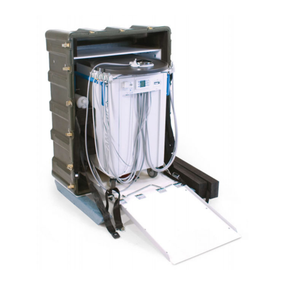
- Page 1 AMC-20CF Mobile Dental System SERVICE MANUAL & PARTS LIST...
-
Page 2: Table Of Contents
TABLE OF CONTENTS Page CONTENTS Page General Service Information ......1 SCALER CONTROL MODULE ......17 Inspection &... -
Page 3: General Service Information
GENERAL SERVICE INFORMATION This service and parts manual offers information and parts The AMC-20CF System uses a single compressor motor with lists not available in the AMC-20CF Operation and a split head. The split head provides pressure on one side and Maintenance Instruction Manual. - Page 4 Water Filters ing with handpiece #1, which is located on the right-hand Inspect the water filters (Fig. 5) on the end of the left arm (Fig. 8). All of the handpieces plus the Figure 5 ends of the water pick-up tubes that curing light and scaler are activated by the air-driven Foot Control.
-
Page 5: Cleaning & Lubrication
Return the electric handpiece to its holder. Cleaning and Lubrication Handpiece Flush Toggle: When servicing the AMC-20CF Mobile Dental System, the To check the handpiece flush toggle switch, which is located on the right-hand side of the unit (Fig. 3), remove a high- parts of any component disassembled should be thoroughly speed handpiece and toggle the switch to the ON position. -
Page 6: Disassembly
DISASSEMBLY NOTE: Most of the plumbing for the AMC-20CF System is looping the instrument hosing through the bulkhead access accessible by lifting the top lid and latching it in the upright opening, swing the right edge of the panel away from the position. -
Page 7: Three-Way Solenoid
bottom of the valve with needle-nose pliers. Remove the tube not to kink the vacuum lines. If a vacuum line is kinked, (PN 730130) on the side with a 7/16" open-end wrench. replace it to prevent later collapse of the line. Remove the mounting screw (PN 510506) from the top of the middle shelf with a 3/32"... -
Page 8: Air Tank
DISASSEMBLY - Continued 5/16" socket or a standard screwdriver. Use a 5/32" Allen the pressure switch cover with a Phillips screwdriver and wrench to remove the two screws (PN 510477) on both sides remove cover. Remove the wires from the switch with a #2 of the angle that attach the upright bracket (PN 461665) to Phillips screwdriver and place on the new switch per the elec- the chassis. -
Page 9: Compressor Motor Assembly
Reassemble the left venturi assembly in the reverse order. Allen wrench Figure 30 Plugs and attach the VENTURI MUFFLER plugs to the new Grasp the venturi assembly and unscrew muffler (PN compressor (Fig. Pressure 330564) from venturi body, either by hand or with a pair of Vacuum 30). -
Page 10: Isolated High-Voltage Terminal Block
DISASSEMBLY - Continued Reassemble the waste pump in the reverse order, referring to ISOLATED HIGH-VOLTAGE TERMINAL BLOCK the electrical schematic for the proper installation. This terminal block Figure 33 2-Pos Jumper (PN 860256) is located 3-Pos Jumper COOLING FAN TERMINAL BLOCK on the lower right side of the chassis base, The cooling fan terminal block (PN 860255) is located on the... -
Page 11: Waste Sensor Connector
IMPORTANT: The AEU-5000 power PCB board is not a user-serviceable WASTE RELAY component of the AMC-20CF system and should be The waste relay (PN 800116) is next to the vacuum relay on returned to Aseptico if repairs are necessary. -
Page 12: 110V Terminal Block
DISASSEMBLY - Continued two 3-position jumpers (PN 860253) with a #2 Phillips screw- 110V TERMINAL BLOCK driver. Remove the two mounting screws (PN 510720) with a The 110V terminal block Figure 45 5/64" Allen wrench and remove block. (PN 860241) is the five- Reassemble the terminal block in the reverse order. -
Page 13: Voltage Selector Switch
VOLTAGE SELECTOR SWITCH er is being replaced. Depress the retaining clips on the inboard side of the circuit breaker and push the breaker out The voltage selector switch (PN 830136) is located on the through the front of the plate. power inlet assembly plate, Figure 53 above the power input con-... -
Page 14: Waste Pump Power Switch
DISASSEMBLY - Continued WASTE PUMP POWER SWITCH the eight screws (PN 510106) Figure 63 holding the power outlet assembly The waste pump power switch (PN 830108) is the white rock- plate with a 5/64" Allen wrench er switch located next to the waste quick-disconnect fitting on and pull the assembly away from the power outlet assembly plate (Fig. -
Page 15: Waste Compartment Door
rear of the unit. Open WASTE TANK SENSOR Figure 67 Mtg. Nut & the door and remove Open waste Washer Figure 71 Sensor Connector the large nut on the compartment door Vacuum Return Tube rear of the latch with a in the rear of the 1-1/16"... -
Page 16: Waste Pump Disconnect
Reassemble the shield in the reverse order, ensuring that the assembly is not a user-serviceable component of the AMC- high vacuum fitting and gasket are aligned with the notch on 20CF system and should be returned to Aseptico if repairs the lid. are necessary. -
Page 17: Scaler Wand
bulkhead. Remove the nut on the Figure 79 line. Trim the ground wire to the proper length and crimp on outboard side of the front panel with a #8 ring terminal. Wrap the cable tie around the scaler cord, a ½" socket. From the inboard side, just above the bulkhead grommet. -
Page 18: Foot Pedal And Tubing
DISASSEMBLY - Continued Remove the black and white fiber optic wires from the white the end of the tube Figure 88 connector (PN 860244) under the manifold (Fig. 85). as before and attach Syringe Block to the syringe block To reassemble the curing with sleeve Figure 85... -
Page 19: System Control Valves
(PN AA-94B) and clear closed and attach the knob with the setscrew, allowing some Figure 91 (PN AA-94C) tubes to clearance between the knob and body. Ensure that the knob the fittings, then remove does not bottom out against the valve. the tubes. -
Page 20: Fiber Optics Module
DISASSEMBLY - Continued FIBER OPTICS MODULE screw (PN 510404) from Figure 101 the bracket (PN 510256) The fiber optics module (PN 730623) is located on the rear to the block with a 1/8" left side of the upper shelf (Fig. 99). Disconnect the sleeve Allen wrench. -
Page 21: System Pressure Gauge
SYSTEM PRESSURE GAUGE CENTRAL VACUUM CANISTER The system pressure gauge (PN 730101) is located on the top The central vacuum (PN AA-290) is located behind the quin shelf, to the left block on the upper shelf (Fig. 107). Remove the tubes (PN Figure 104 Gauge of the quin block... -
Page 22: Amalgam Manifold
DISASSEMBLY - Continued AMALGAM MANIFOLD pressure release toggle Figure 114 switch. Unscrew Open the waste compartment door. Remove the amalgam Couplings Gasket water bottles, complete separator (PN 730595) or bypass filter (PN 730615). Remove Bracket with their caps, from the the two tubes (PN AA-86G) going to the amalgam manifold cap couplings on the (PN 730596-01): one from the waste container and the other... -
Page 23: Instrument Holders
Refer to the electrical schematic for the proper size and ing the sides of the length of the wire to be replaced. Fasteners divider wall with a 5/64" Allen wrench THIS COMPLETES THE DISASSEMBLY PROCEDURE (Fig. 119). Remove FOR THE AMC-20CF DENTAL SYSTEM. Page 21... - Page 24 FINAL ASSEMBLY PARTS LIST Figure A (Sheet 1 of 11) ACCESSORY TRAY ASSEMBLY SEE FIG. B, Page 35 LEFT SIDE PANEL ASSEMBLY SEE FIG. C, Page 35 RIGHT SIDE PANEL ASSEMBLY SEE FIG. D, Page 36 FRONT PANEL ASSEMBLY SEE FIG. F, Page 36 NOTE: Refer to Pages 33 &...
- Page 25 FINAL ASSEMBLY PARTS LIST Figure A (Sheet 2 of 11 - Front View) PEDAL HANDPIECE BLOCK ASSEMBLY SEE FIG. Z, Page 46 BULKHEAD ASSEMBLY SEE FIG. X, Page 45 PUMP & BRACKET ASSEMBLY SEE FIG. M, Page 40 MIDDLE SHELF ASSEMBLY SEE FIG.
- Page 26 FINAL ASSEMBLY PARTS LIST Figure A (Sheet 3 of 11 - Right Side View) WASTE SHIELD ASSEMBLY SEE FIG. W, Page 45 PUMP & BRACKET ASSEMBLY SEE FIG. N, Page 40 AIR TANK ASSEMBLY SEE FIG. I, Page 38 MIDDLE SHELF ASSEMBLY SEE FIG.
- Page 27 FINAL ASSEMBLY PARTS LIST Figure A (Sheet 4 of 11 - Left Side View) WASTE SHIELD ASSEMBLY SEE FIG. W, Page 45 PUMP & BRACKET ASSEMBLY SEE FIG. N, Page 40 AEU-5000 MOUNT ASSEMBLY SEE FIG. F, Page 37 MIDDLE SHELF ASSEMBLY SEE FIG.
- Page 28 FINAL ASSEMBLY PARTS LIST Figure A (Sheet 5 of 11 - Back View) POWER OUTLET ASSEMBLY SEE FIG. R, Page 42 POWER INLET ASSEMBLY SEE FIG. S, Page 43 REAR PANEL ASSEMBLY SEE FIG. Q, Page 41 NOTE: Refer to Pages 33 & 34 for Parts Descriptions Page 26...
- Page 29 FINAL ASSEMBLY PARTS LIST Figure A (Sheet 6 of 11 - Top View) MANIFOLD 4-PORT ASSEMBLY SEE FIG. A-A, Page 46 QUIN AUTO BLOCK ASSEMBLY SEE FIG. A-B, Page 47 LEFT SIDE PANEL ASSEMBLY SEE FIG. C, Page 35 RIGHT SIDE PANEL ASSEMBLY SEE FIG.
- Page 30 FINAL ASSEMBLY PARTS LIST Figure A (Sheet 7 of 11 - Front View) BULKHEAD ASSEMBLY SEE FIG. X, Page 45 66 8 SYRINGE BLOCK ASSEMBLY SEE FIG. Y, Page 45 PEDAL HANDPIECE BLOCK ASSEMBLY SEE FIG. Z, Page 46 FRONT VIEW VACUUM VALVE ASSEMBLY SEE FIG.
- Page 31 FINAL ASSEMBLY PARTS LIST Figure A (Sheet 8 of 11 - Right Side View) PUMP & BRACKET ASSEMBLY SEE FIG. N, Page 46 RIGHT SIDE VIEW NOTE: Refer to Pages 33 & 34 for Parts Descriptions Page 29...
- Page 32 FINAL ASSEMBLY PARTS LIST Figure A (Sheet 9 of 11 - Left Side View) MIDDLE SHELF ASSEMBLY SEE FIG. O, Page 41 AEU-5000 MOUNT ASSEMBLY SEE FIG. F, Page 37 LEFT SIDE VIEW FRONT CASTER MIDDLE SHELF ASSEMBLY (X2) SEE FIG. O, Page 41 REAR CASTER (X2)
- Page 33 FINAL ASSEMBLY PARTS LIST Figure A (Sheet 10 of 11 - Back View) BACK VIEW WASTE TANK ASSEMBLY SEE FIG. T, Page 43 POWER INLET ASSEMBLY SEE FIG. S, Page 42 POWER OUTLET ASSEMBLY REAR PANEL ASSEMBLY SEE FIG. R, Page 42 SEE FIG.
- Page 34 FINAL ASSEMBLY PARTS LIST Figure A (Sheet 11 of 11 - Top View) MANIFOLD 4-PORT ASSEMBLY SEE FIG. A-A, Page 46 ARMS ASSEMBLY SEE FIG. A-C, Page 46 VIEW QUIN AUTO BLOCK ASSEMBLY SEE FIG. A-B, Page 47 NOTE: Refer to Pages 33 & 34 for Parts Descriptions Page 32...
- Page 35 FINAL ASSEMBLY PARTS LIST (Sheet 1 of 2) Ref Figure A ITEM PART NO ITEM PART NO LABEL AIR SYRINGE WATER AMC-20 420748-07 FINAL ASSY AMC-20CF DUAL VOLTAGE 120356 TUBING POLY 1/4OD CLR AA-95C 3.79' CASE AMC-20 CART 410195 FTN BARB 1/16 DELRIN TEE...
- Page 36 SIDE PANEL SUPPORT BLOCK LONG AMC-20 461710 HOLE PLUG 1.0 NYLON BLK 510705 AUXILIARY POLE SUPPORT AMC-20 461793 BRACKET AUXILIARY SUPPORT AMC-20CF 461878 C/S BTNSOC STNLS 1/4-20 X 7/8 510257 BUMPER SORBOTHANE 70 DURO 8-32 MALE BLK 510700 LABEL CAUTION LID SUPPORT AMC-20...
- Page 37 ITEM PART NO INSULATION SIDE LEFT BOTTOM AMC-20 461918 HANDLE STANDOFF AMC-20 461709 RING RETAINING EXTERNAL 5/8 DIA SHAFT 510674 LABEL AMC-20CF 420845 PANEL LEFT SIDE AMC-20 461702-01 INSULATOR LEFT SIDE AMC-20 461754 INSULATION SIDE LEFT FILL AMC-20 461919 Page 35...
- Page 38 SIDE CONTROLS INSERT MODULAR FRAME 461740 WATER BOTTLE INSERT MODULAR FRAME 461739 NUT NYLOC 8-32 STNLS 510411 INSULATION BOTTLE WELL AMC-20 461922 LABEL AMC-20CF 420845 INSULATION RIGHT SIDE TOP AMC-20 461923 PANEL RIGHT SIDE SILKSCREENED AMC-20 461701-01 INSULATION RIGHT SIDE UPPER TOP AMC-20 461924...
- Page 39 PARTS LIST - Figure F - AEU-5000 Mount Assembly ITEM PART NO ITEM PART NO HOUSING OUTLET CONNECTOR 5000 MOUNT 461886 LCD DISPLAY AEU-5000 880232 M/S PHPHIL 6 X 3/8 PLASTITE 48-2 HARD STEEL 510650 PCB ASSY DISPLAY AEU-5000 COATED 330553-C LINECORD REMOTE US 6FT BLK 15A MOD 840041-01...
- Page 40 PARTS LIST - Figure H - Relief Valve Assembly ITEM PART NO ITEM PART NO TOP VACUUM VALVE 461853 PLUNGER VACUUM VALVE 461850 C/S BTNSOC STNLS 6-32X1/2 510036 O-RING .837ID X .058CS SL70 TABLE 300028 520004 FTN BARB 10-32 X 1/16 PLATED 730062 FTN PLUG BRASS 1/8 MPT HEXHD CNTRSUNK 730341...
- Page 41 PARTS LIST - Figure J - Right-Hand Venturi Assembly ITEM PART NO ITEM PART NO MUFFLER ASSY AMC-20 330564 C/S BTNSOC STNLS 8-32X1/4 510309 GASKET NYLON #10 730074 FTN 1/8FPT 1/4POLY 90 DEG. ELB 730351 EDGE TRIM 1/16ID X1/4 X 1/4 RUBBER 730378 2.00"...
- Page 42 PARTS LIST - Figure M - Compressor Motor Assembly ITEM PART NO ITEM PART NO MAIN PLATE MOTOR MOUNT AMC-20 461899 C/S BTNSOC STNLS 1/4-20 X 5/8 510503 C/S BTNSOC STNLS 1/4-20X1-1/4 510295 FTN 3/8MPT X 1/4 POLY ELBOW 730638 GROMMET BUSHING SORBOTHANE 70 DURO 870315 FTN PUSH-IN ELB 1/2TUBEX3/8MPT VITON TYPE 730360...
- Page 43 PARTS LIST - Figure O - Middle Shelf Assembly ITEM PART NO ITEM PART NO FAN TUBEAXIAL 106 CFM 4.69 SQ X 1.5 THK 540012 INSULATOR STRIP AMC-20 461972 C/S BTNSOC STNLS 6-32X3/8 510160 FTN 1/4 POLY X 1/8MPT POLYTITE 730117 FTN PLUG BRASS 1/8 MPT HEXHD CNTRSNK 730341...
-
Page 44: Figure R – Power Outlet Assy
PARTS LIST - Figure Q - Rear Panel Assembly ITEM PART NO ITEM PART NO INSULATION NOISE REAR DOOR AMC-20 461927 FAN GUARD PLASTIC 4.53X .10 TK 540009 C/S BTNSOC STNLS 8-32X3/4 510506 C/S BTNSOC STNLS 6-32X3/8 510160 INSULATOR REAR WALL AMC-20 461781 NUT NYLOC 8-32 STNLS 510411... - Page 45 461772 WASHER LOCK PUSH-ON CIRCUIT BREAKER 510690 NUT NYLOC 4-40 STNLS HEX 510394 CIRCUIT BREAKER 1 AMP THERMAL PANEL MNT 830138 LABEL VOLTAGE SELECTOR SWITCH AMC-20CF 420615-08 PLATE POWER INLET DUAL SILKSCREENED 461769-01 SWITCH HIGH INRUSH 16AMP DPDT ON-ON 830136...
- Page 46 PARTS LIST - Figure U - Noise Baffle Assembly ITEM PART NO ITEM PART NO RIVET BLIND AL/AL 1/8D3/16-1/4 510170 M/S STNLS RNDSLT 2-56X3/4 510088 WASHER BLIND RIVET 1/8 510198 INSULATION NOISE BARRIER TOP AMC-20 461925 NUT NYLOC 4-40 STNLS HEX 510394 INSULATION NOISE BARRIER SIDE AMC-20 461926...
-
Page 47: Figure X – Bulkhead Assy
PARTS LIST - Figure W - Waste Shield Assembly ITEM PART NO ITEM PART NO STRAP CONDUIT 1/2 INCH 510686 M/S STNLS FLAPHL 6-32X3/8 510407 NUT NYLOC 6-32 STNLS 510395 EDGING 1/2 X 1/8 VINYL/NITRILE BLK 730394 4.35" LABEL WASTE FLOW VALVE AMC-20 420550-10 NUT NYLOC 8-32 STNLS 510411... - Page 48 PARTS LIST - Figure Y - Syringe Block Assembly ITEM PART NO ITEM PART NO BLOCK INTERFACE SYRINGE AMC-20 461775 FTN BARB 10-32 X 1/16 PLATED 730062 GASKET NYLON #10 730074 PARTS LIST - Figure Z - Pedal Handpiece Block Assembly ITEM PART NO ITEM...
- Page 49 PARTS LIST - Figure A-B - Quin Auto Block Assembly ITEM PART NO ITEM PART NO FTN BARB 10-32 X 1/16 PLATED 730062 BLOCK AUTO HPCE CONTROL QUIN 730621 FTN PLUG 10-32 HEX BRT/NKL 730072 PARTS LIST - Figure A-C - Arms Assembly ITEM PART NO ITEM...
-
Page 50: Sterilization & Maintenance
STERILIZATION AND MAINTENANCE: Excessive dust and debris may cause a drastic decrease in Because of its simple design, the Aseptico AMC-20CF optical output. In the event that the light requires cleaning, Mobile Dental System requires very little maintenance. Any first try a gentle swabbing, using a lint-free swab. If need- maintenance that is needed can be performed in minutes. - Page 51 WASTE REMOVAL: ULTRASONIC SCALER: Routinely drain the waste container once a day (see Waste (Refer to ultrasonic scaler instructions for use, supplied sepa- System on page 3 for step-by-step instructions). Since the rately.) unit uses a filtered amalgam separator, no settlement time The Scaler Handpiece Cover and Instrument Tips are is required before draining the waste tank.
-
Page 52: Troubleshooting Guide
TROUBLESHOOTING GUIDE Problem: Correction: Check system power connection. Unit will not start Check voltage selector switch for proper voltage. Check circuit breakers. Check if waste tank sensor is connected. Check if waste tank is full. Check source circuit to see if it is a minimum of 15A. Unit starts but trips circuit breakers NOTE: Operating the unit off an extension cord is not recommended. -
Page 53: Final Inspection & Testing
FINAL INSPECTION AND TESTING - Procedure for Aseptico AMC-20CF - F-4.10-02-A (Testing specs subject to change. Refer to latest Schematic sprays from handpiece outlet in a uniform spray. Adjust Drawing Set, PN 420872, sheets 31 & 32 for updates.) water coolant flow valve from minimum to maximum flow EXAMINATION FOR DEFECTS: to verify proper function. -
Page 54: Required Tools List
Required Tools List Allen Wrenches: 5/8" 1/16" 3/4" (Qty: 2) 5/64" 13/16" 3/32" 22mm 1/8" 7/8" 5/32" 27mm 3/16" 1-1/16" 1/4" Screwdrivers: 3/64" Standard Socket Wrenches: 5/16" #1 Phillips 7/16" #2 Phillips 1/2" Electrical Tools: Wire Stripper Combination Wrenches: 1/4" Crimp Tool 5/16"... -
Page 55: Specifications
(130°F) 10°C -40°C (50°F) (-40°F) IMPORTANT NOTE When running the AMC-20CF With regard to setting the unit at 50Hz, expect approxi- handpieces pressure, mately 17% less vacuum and 'kgcm ' and 'bar' are equiv- CONFORMS TO UL STD 60601-1; CERTI- pressure volume due to slower FIED TO CSA STD C22.2 NO. -
Page 56: Warranty
This warranty pertains only to the specific repair. Any new and different defect in materials or workman- ship will be treated as a new repair. If the product is not covered under warranty, Aseptico offers Repair Services for a fee.
Need help?
Do you have a question about the AMC-20CF and is the answer not in the manual?
Questions and answers