
Related Manuals for Aseptico Transport III


Summary of Contents for Aseptico Transport III
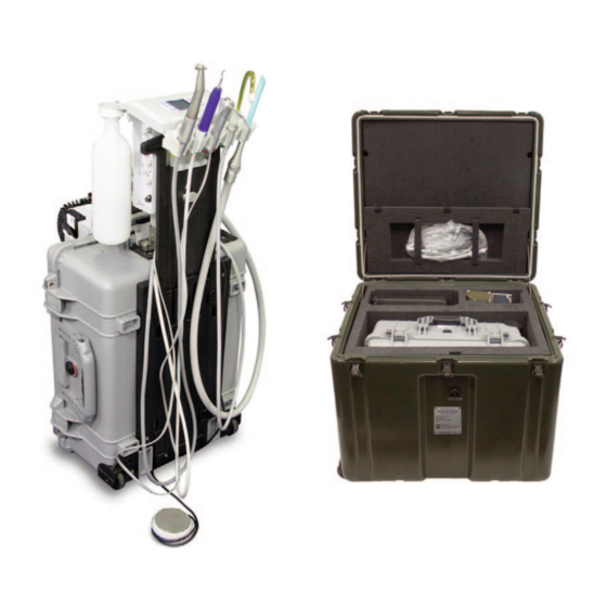
- Page 1 AEU-525CF AEU-525CFH AEU-525CFH-14 Portable Dental System Transport III SERVICE MANUAL & PARTS LIST...
-
Page 2: Table Of Contents
TABLE OF CONTENTS CONTENTS Page Page General Service Information ......1 STERILIZATION & MAINTENANCE ....24-25 Inspection &... -
Page 3: General Service Information
INSPECTION & OPERATION VERIFICATION unit's power switch OFF and check for air leaks in the To verify that the Transport III unit is functioning properly, first system. If the system pressure gauge is showing pressure, follow the Setup procedure the leaking sound should be detectable. -
Page 4: Cleaning & Lubrication
Both instruments are activated Cleaning and Lubrication: by the foot control. When servicing the Transport III system, the parts of any Electric Motor/Handpiece component disassembled should be thoroughly cleaned and Remove the electric motor/handpiece from its holder (Fig. 3). -
Page 5: Esd Precautions
Water Lines ESD PRECAUTIONS Disinfect the water lines weekly. Prepare a 1:10 bleach The following electrostatic controls must be used when solution (1 part household bleach to 9 parts water). working on this unit: Remove water supply bottle and discard residual water. ESD Training and Standards: Replace the empty water supply bottle and air purge all Employees handling electronic sub-assemblies and ESD... -
Page 6: Disassembly
Transport III case lid, to loosen the four assembly. Place Bottle aside for reassembly later. fasteners on the Filter frame (Fig. 10). Turn the fasteners... -
Page 7: Foot Control
Air/Electric Module Assembly (Fig. 16). Pull the connector straight out of its receptacle only by the locking The Transport III Foot Control connector is located on the collar. Set Motor/Cord aside. When reconnecting the motor bottom of the Air/Electric Module Assembly (Fig. 14). Loosen... -
Page 8: Instrument Holders
DISASSEMBLY - Cont'd blue tube (PN AA-94B) and clear tube (PN AA-94C) from the to remove the two mounting screws (PN 510037). Reassemble the Guard in the reverse order. fittings on the cap. Remove the three mounting screws (PN 510404) from the top of the panel (Fig. 18) with a 3/32" Allen INSTRUMENT HOLDERS wrench and remove cap. -
Page 9: Rear Wall
Aseptico if repairs are required. Wall and move to work bench. Remove the two Fittings (PN 730062) and gaskets (PN 730074) with a 1/4" open-ended The Control Panel Membrane (PN 420918) is attached to wrench. Use a 9/16" wrench to remove the Toggle Valve... -
Page 10: Manifold Assembly
Board's connectors. Remove Power Board from Module and set aside for reassembly later. IMPORTANT: The Power Board Assembly is not a customer-serviceable item. Return the Board Assembly to Aseptico if repairs are necessary. SCALER DISABLE Pull the inboard Insulator (PN 462113) off the four nylon SWITCH mounting Standoffs (PN 462112) (Fig. -
Page 11: Junction Block
FUSE remaining sleeve clamps and tubes as necessary. HOLDER (PN 810438) IMPORTANT: The Manifold Block (Fig. 33) is not a customer- serviceable item. Return the Block to Aseptico if repairs are required. Figure 33 JUNCTION BLOCK 1/8" TUBE 1/4" HOSE... -
Page 12: Scaler Control Module
DISASSEMBLY - Cont'd SCALER CONTROL MODULE Figure 44a Figure 44b Scaler Figure 49 Control Module (PN 840140) is located on the upper left side 12-PIN CONNECTOR of the Manifold BLOCK JUNCTION Module Front BLOCK MOUNTING Wall. Slide the MOUNTING SCREWS (X3) SCREW cover of the At the workbench, use a flat-head screwdriver to remove the... -
Page 13: Electric Motor Receptacle
At the workbench, disconnect the remaining two sleeve SYRINGE AND SYRINGE TUBING clamps and To replace the Syringe (PN TA-90D), remove the two sleeve Figure 52 CROSS hoses from clamps (PN 730015) from the Syringe tube splices located FITTINGS PLUGS PN 730139 inside the bottom panel of the Air &... -
Page 14: Footswitch Connector
Return the Wand to Aseptico if repairs are AIR BOTTLE ASSEMBLY required. The Air Bottle Assembly is located inside the Transport III Reassemble the Scaler Wand in the reverse order, adjusting Case, in the upper right-hand corner of the top compartment... -
Page 15: Divider Wall
Screws (PN compartment of the 510037) that mount the DIVIDER Transport III Case WALL Panel to the Compressor. (Fig. 67). Use a Remove Panel (see Fig. 73) and place aside for reassembly LOWER 5/64"... -
Page 16: Motor Housing Cover
Replace the entire Supply The Electrical Panel is located beneath the Motor Housing or return it to Aseptico if repairs are required. Locate the Cover (Fig. 79). Locate the Display Module Power Cable Cable Clamp (PN 510410) for the Display Module Power... -
Page 17: Display Module Power Cable
BOARD PCB and set aside the 875120 wire assembly for pins on the PCB . IMPORTANT: The Power Supply and reuse later. Control Board PCB assemblies are not customer serviceable. If repairs are required to either assembly, replace the entire item or return it to Aseptico for service. -
Page 18: Waste Connector Cable Assembly
DISASSEMBLY - Cont’d WASTE CONNECTOR CABLE ASSEMBLY colors and terminal positions of the eight wires coming from the Compressor Motor Assembly. Use a 1/8” flat blade Locate the Waste Figure 87 MTG SCREW (X2) screwdriver to detach these eight wires from the Block. Connector Cable WASTE... -
Page 19: Circuit Breakers
CIRCUIT BREAKERS Remove the six red flag-type wire connectors from the terminals on the Compressor Breaker. The Circuit Breaker Housing (PN 462017) is located on the front of the Electrical Panel. The Housing provides an enclosure for the Power Entry Circuit Breaker (PN 840119), Cut the three cable ties (PN 510137) around the wire Compressor Circuit Breaker (PN 830151), and the Voltage bundles on the back side of the Panel (see Fig. -
Page 20: Power Inlet Line Filter (Emi)
DISASSEMBLY - Cont’d Assembly MOTOR HOUSING - LEFT WALL ASSEMBLY Figure 95 COMPRESSOR LED CABLE ASSY 875117) from the The Left Wall (PN 462010) of the Motor/Compressor can be CIRCUIT two LED Diffuser detached as a subassembly and then moved to a work BREAKER Lenses bench for component disassembly. -
Page 21: Motor Housing - Right Wall Assembly
MOTOR HOUSING Figure 99 RIGHT WALL ASSEMBLY - RIGHT WALL Locate Figure 98 ASSEMBLY mounting Screws For the Right Wall (PN 510037) in the (PN 462016) use an top left corner of the MOUNTING open-end wrench to SCREWS Left Wall Assembly (X2) detach the nut at the ELBOW... -
Page 22: Venturi & Muffler Bracket Assembly
DISASSEMBLY - Cont’d Remove Switch, Elbow, and Washer and set aside for Figure 102 CABLE TIE(S) HOSE FITTING reassembly later. Switching Module Manifold (PN 330594): On the inboard PRESSURE SWITCH side of the Wall (Fig. 103), use diagonal cutters to pry the ELBOW two 1/8"... -
Page 23: Compressor/Vacuum Pump Assembly
and vacuum on the other (Figs 106a & 106b). The Compressor motor includes a vibration mount assembly, IMPORTANT: Disassembly of the Venturi & Muffler Bracket which is bolted to the bottom of the AEU-525CF Case (see Assembly is not recommended unless component Fig. -
Page 24: Motor Mount Assembly
Allen wrench to remove the 1/4" Plugs (PN 730098) from the FASTENERS (X2) Compressor Heads. IMPORTANT: The Compressor Motor is not a customer- LOCK BLOCK serviceable item. Return the Motor to Aseptico if repairs are MOUNTING required. SCREWS (X3) MOTOR MOUNT ASSEMBLY the seven mounting Screws (PN 510790) and rectangular... - Page 25 Washer (PN 510445) with a Phillips screwdriver and detach THIS COMPLETES THE DISASSEMBLY PROCEDURE Tool from Case, if necessary. FOR THE AEU-525CF TRANSPORT III SYSTEM. Locate the Case Vent Door (PN 462004) on the outboard side of the Lid (see Figs. 109 & 110). Unlock the four Door Fasteners (PN 510772) and swing the Door open to expose the two Hinges (PN 462005) and Hinge Stop (PN 510777).
-
Page 26: Sterilization & Maintenance
Because of its simple design, the Aseptico AEU-525CF The lens of the LED light on the motor (see Fig. 124) is soft Transport III System requires very little maintenance. Any maintenance that is needed can be performed in minutes. and can be damaged. It should not be exposed to dust and debris. - Page 27 AIR BOTTLE AND FILTER: NOTE: Since only the tips can be autoclaved, it is recommended that the air/water syringe be bagged with a Routinely check the air bottle filter once a day for disposable, single-use plastic sleeve between each patient condensation.
-
Page 28: Troubleshooting Guide
TROUBLESHOOTING: Correction: • Check system power connection. • Check if both circuit breaker switches are On. • Check if waste container sensor is connected. • Check if waste container is full. • Check if fan is blocked or inoperative. • Check source circuit to see if it is a minimum of 15A. •... -
Page 29: Replacement Parts List
REPLACEMENT PARTS LIST ITEM PART NO ITEM PART NO WASTE TANK ASSEMBLY AEU-525 330603 BOTTLE 750 ML (25 OZ) BLOW MOLDED HDPE (AIR) 730657 INLINE STRAINER WASTE CONTAINER (HVE 462124 LINECORD REMOTE US 10 FT HOSP GREY 15A/125A 840049 O-RING .125ID X .070CS VT70 (AIR-JUNCTION) 520025 LINECORD REMOTE EURO BLACK 2.5 M 840007... - Page 30 FINAL INSPECTION AND TESTING - Procedure for Aseptico AEU-525CF - F-4.10-02-B (Testing specs subject to change. Refer to latest Schematic bottle cap. Switch to ‘Purge’ and replace the water Drawing Set, PN 420991, Sheets 16-18 for updates.) bottle. EXAMINATION FOR DEFECTS: C.
- Page 31 preset number stops flashing. Now press the footpedal F. Performance Test (Syringe): to turn on the motor and LED and then release it and 1. Fill the water bottle and turn on the compressor to fill verify that the LED remains on for 20 +/-5 seconds. the air reservoir.
-
Page 32: Final Inspection & Testing
FINAL INSPECTION AND TESTING - Cont’d Test Details: 6. Dielectric Withstand Test - Mains to the combined foot pedal wires. a. Connect the power cord from the test equipment to Test parameters: Test voltage 4350 VDC, Ramp 1 the mains power inlet of the AEU-525, and the return second, Dwell 1 second, Leakage limit 1 mA, Arc Fail is lead of the Ground Bond Tester to the chrome plated OFF. -
Page 33: Symbol Definitions
SYMBOL DEFINITIONS: High Volume Evacuator (HVE) Type BF Equipment Attention, consult accompanying documents Pressure Gauge Motor Direction Consult Instructions For Use Light Controls Manufacturer Footswitch Dangerous Voltage On/Off Switch - Mains Alternating current Atmospheric Pressure Limitation Temperature Limitation Water Counterclockwise to Increase/Open Humidity Limitation Clockwise to Decrease/Close Electric Handpiece... -
Page 34: Required Tools List
REQUIRED TOOLS LIST Allen Wrenches: Screwdrivers: 1/16" 1/4" Standard, Slot 5/64" 3/64" Standard Slot (Jeweler's) 3/32" #1 Phillips 1/8" #2 Phillips 9/64" Electrical Tools: 5/32" Wire Stripper Crimp Tool 3/16" Panduit Model CT-1551 (or equivalent) 1/4" Molex 640014100 (or equivalent) Diagonal Cutters Combination Wrenches: 1/4"... -
Page 35: Specifications
SPECIFICATIONS Transport III Case Size: ..17.93” W x 22.06” L x 10.43” H (45.5 cm x 56 cm x 26.5 cm) Shipping Case Size: ..30.5” W x 25.75” L x 24.75” H (77.47 cm x 65.40 cm x 62.86 cm) -
Page 36: Warranty
During the specific warranty periods set forth above, Aseptico will, at its option, repair or replace the product(s) or particular part(s) that are found to be defective in either material or workmanship in part or whole. Aseptico shall be the sole arbiter of such action.
Need help?
Do you have a question about the Transport III and is the answer not in the manual?
Questions and answers