Table of Contents
Advertisement
Quick Links
Advertisement
Table of Contents

Related Manuals for Aseptico AEU-525 Transport III


Summary of Contents for Aseptico AEU-525 Transport III
- Page 1 AEU-525 Portable Dental System Transport III OPERATION & MAINTENANCE MANUAL...
-
Page 2: Table Of Contents
INDICATIONS FOR USE: electromagnetic interference, position this device away from RF transmitters and other sources of electromagnetic energy. The AEU-525 Transport III is a portable self-contained dental system that is used for endodontic and general dentistry applications. MEDICAL -- GENERAL MEDICAL EQUIPMENT... -
Page 3: Introduction
Your new Aseptico AEU-525 Transport III System is the finest portable electric dental system available. The System features a high-torque brushless micro motor with digital controls for the handpiece ratios, speed, torque, motor direction, and LED illumination. The dual-voltage system... -
Page 4: Safety Precautions
SAFETY PRECAUTIONS: Aseptico accepts no liability for direct or consequential injury or damage resulting from improper use, arising in particular through the non-observance of the operating instructions, or improper preparation and maintenance. WARNING: Clean, disinfect, and sterilize new or repaired handpieces and instruments before first use and between each patient use. -
Page 5: Setting Up The Unit
Unhook waste-bottle bungee cord and remove waste bottle. LOCKING c. Loosen air/electric-module holding strap BOTTOM SLOT and remove air/electric module assembly. Also refer to the Aseptico Transport III video at www.aseptico.com for basic setup instructions. -
Page 6: Setting Up The Unit
SETTING UP THE UNIT - Cont’d 9. (NOTE: The user might have chosen to 7. Open the FIG. 6 interchange Step 9 with Step 8, for easier small metal setup of the syringe and optional scaler.) door on the Place air/water top of the case FIG. - Page 7 the seals, resulting in poor performance.) Lock the module into place by hand- tightening the hold-down thumb-screw on FIG. 10 the housing, until snug (Fig 13b). FIG. 13a FIG. 13b FOOT CONTROL CONNECTOR 12. Fill the water-supply bottle with clean water or HOLD-DOWN other suitable irrigation fluid and attach to the CONNECTOR...
- Page 8 SETTING UP THE UNIT - Cont’d housing to the ‘ON’ (I) position. The left- FIG. 15a FIG. 15b hand FIG. 18 switch turns ROTATING POWER the unit LATCH ON/OFF power COMPRESSOR ON/OFF On/Off SALIVA EJECTOR HOSE ALIGNMENT also HOSE acts as VOLTAGE SELECTOR Place the HVE and saliva ejector valves SWITCH...
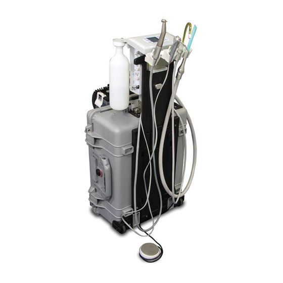
- Page 9 FIG. 21 - AEU-525 Transport III - Front View HIGH VOLUME WATER SUPPLY EVACUATOR (HVE) BOTTLE SALIVA EJECTOR WASTE SYRINGE CONTAINER SCALER ELECTRIC MOTOR MANIFOLD PANEL (Pages 14 - 15) ELECTRIC MOTOR CONTROL PANEL (Pages 10-13) SCALER CONTROLS HANDPIECE WATER...
- Page 10 SETTING UP THE UNIT- Cont’d FIG. 22 - AEU-525 Transport III - Back View WATER BOTTLE PURGE SWITCH AIR/ELECTRIC MODULE ASSEMBLY WATER BOTTLE LOW VACUUM HOSE INSTRUMENT HOLDERS (Page 10) HIGH VACUUM HOSE WASTE CONTAINER HOSE SALIVA LEVEL EJECTOR SENSOR...
- Page 11 FIG. 23 - AEU-525 Transport III - Back View WASTE 85% FULL ALARM LED (Page 16) WATER BOTTLE PURGE SWITCH (Page 6) RED LED WASTE SENSOR CONNECTOR POWER ENTRY AND CIRCUIT BREAKER PANEL (Page 6) COMPRESSOR POWER ON/OFF INLET SWITCH ON/OFF &...
-
Page 12: Operation Functions
OPERATION FUNCTIONS: 1. ON/OFF POWER SWITCH & CIRCUIT be 'On' and the instrument removed from its BREAKER (Fig. 24) - Controls power holder before operation can begin. NOTE: On/Off to the Transport III. When the unit is The HVE and saliva ejector are not turned On, the green LED next to the controlled by the Foot Control - they will power switch will illuminate. - Page 13 Fig. 28 - Transport III Electric Motor Control Panel PRESET SELECTOR HANDPIECE RATIO w/DISPLAY SELECTOR w/DISPLAY MOTOR DIRECTION CONTROL PANEL (FWD/REV) SELECTOR STANDBY w/DISPLAY BUTTON ENDODONTIC MODE SPEED (RPM) (ENDO) SELECTOR SELECTOR w/DISPLAY w/DISPLAY TORQUE ILLUMINATION SELECTOR CONTROL w/DISPLAY w/DISPLAY -OR- ILLUMINATION SELECTOR...
- Page 14 OPERATION FUNCTIONS - Cont'd: CUSTOMIZING RATIOS: 7) Press and release the ILLUMINATION button to turn the hand- The user can enable or disable individual piece LED On/Off. To handpiece ratio options, so that only preferred activate the handpiece or commonly used ratios are displayed during and LED, remove the handpiece from its the ratio selection process.
- Page 15 Figure 31 - Factory Default Presets PRESET SPEED ENDO MODE DIRECTION TORQUE HANDPC RATIO (RPM) (8:1 Ratio Only) 200,000 100 % — 150,000 100 % — 150,000 50 % Torque Limit — 100,000 100 % — 100,000 50 % Torque Limit —...
- Page 16 OPERATION FUNCTIONS - Cont’d: SLEEP MODE: FIG. 32 After 20 minutes of motor inactivity, the SCALER electric motor module automatically enables ULTRASONIC an energy-saving Sleep Mode which turns CONTROL SWITCH off the display. When in this mode, three square symbols will blink consecutively across the darkened LCD.
- Page 17 8. HANDPIECE CONTROLS: a.) Toggle the bottle pressure relief valve Water - The handpiece water toggle valve to “PURGE” (see Fig. 35) to remove allows water to flow to the working hand- pressure from the water bottle. piece when the foot pedal is depressed. The b.) Unscrew the bottle from its cap.
-
Page 18: Operation Functions
Each compartment auxiliary water output using an Aseptico includes its own 85%-full sensor. When fitting (PN AA-60) attached to tubing. The either one of these sensors reaches the... -
Page 19: Operation
OPERATION: 1. After the Transport III unit has been set up TORQUE - Adjust the up/down TORQUE and you have made yourself familiar with arrows on the display to the desired the operation functions, you are ready for torque. operation as follows: MOTOR DIRECTION - Select either 2. - Page 20 OPERATION - Cont’d 9. Using the HVE and Saliva Ejector b. Screw on a sterile Instrument Tip to the Vacuums: Scaler handpiece and tighten it firmly. Adjust the vacuum pressure on the HVE Turn carefully backwards approximately (high vacuum) and saliva ejector (low 1mm.
-
Page 21: Sterilization & Maintenance
STERILIZATION AND MAINTENANCE: Because of its simple design, the Aseptico Fig. 40 - MOTOR & CORD STERILIZATION AEU-525 Transport III System requires very little maintenance. Any maintenance that is needed can be performed in minutes. PURGING THE SYSTEM: If the unit will not be used for an extended period of time, or if the unit might be The entire motor &... -
Page 22: Sterilization & Maintenance
STERILIZATION AND MAINTENANCE - Cont'd: Fig. 41 CAUTION: O-Rings Do not run saline solutions through the water system -- saline will rust the water filters. VACUUM SYSTEM: The HVE and low volume saliva ejector valves are fully autoclavable. Remove the valves from their hoses before autoclaving. - Page 23 3-WAY AIR/WATER SYRINGE: MOTOR/CORD RECEPTACLE O-RINGS Depress the right button for air operation, The O-rings (PN 520081) for the three and the left button for water operation. water/air ports in the motor/cord receptacle Depressing both buttons will create a mist. should be replaced if damaged or worn.
-
Page 24: Repacking Instructions
TRANSPORT III REPACKING INSTRUCTIONS: 1. Remove all water and liquid wastes from 9. Coil foot pedal cable around pedal, put water bottle and/or waste container. Clean the into plastic bag and place on top of motor bottle and container per the instructions found housing, in the recess shown in Fig. -
Page 25: Troubleshooting
TROUBLESHOOTING: Problem: Correction: Unit will not start: • Check system power connection. • Check if both circuit breaker switches are On. • Check if waste container sensor is connected. • Check if waste container is full. • Check source circuit to see if it is a minimum of 15A. Unit starts but trips circuit breaker: •... -
Page 26: Replacement Parts List
REPLACEMENT PARTS LIST ITEM PART NO WASTE TANK ASSEMBLY AEU-525 330603 INLINE STRAINER WASTE CONTAINER (HVE STRAINER) 462124 O-RING .125ID X .070CS VT70 (AIR-JUNCTION) 520025 O-RING .320ID X .O28 CS VITON 70 (E-HEAD) 520069 O-RING .042ID X .142 X .050 W VITON (MTR RECEPTCL) 520081 O-RING .208 ID X .070 CS VITON AS568-009 (AIR-JUNCTION) 520121... -
Page 27: Symbol Definitions
SYMBOL DEFINITIONS: Saliva Ejector Type B Equipment Type BF Equipment High Volume Evacuator (HVE) Attention, consult Pressure Gauge accompanying documents Consult Instructions For Use Motor Direction Light Controls Manufacturer Dangerous Voltage Footswitch On/Off Switch - Mains Alternating current Atmospheric Pressure Limitation Water Temperature Limitation Counterclockwise to Increase/Open... -
Page 28: Specifications
SPECIFICATIONS: Transport III Case Size: 17.93” W x 22.06” L x 10.43” H (45.5 cm x 56 cm x 26.5 cm) IMPORTANT 525 Weight (fully loaded): 57 lbs (25.8 kg) When running the AEU-525 Power Source: AC Manual-Switching unit at 50Hz, expect approxi- 115/220/230 VAC at 60/60/50 Hz mately 17% less vacuum and Power Rating:... -
Page 29: Warranty
WARRANTY Aseptico warrants its products against defects in material or workmanship for a period of two (2) years, from date of original invoice. Some handpieces are warranted for one year under the same conditions. Other handpieces and expendable components, such as air turbines and light bulbs, are covered by shorter warranty periods, or have no warranty. -
Page 30: Notes
NOTES... - Page 31 NOTES...
-
Page 32: P.o. Box 1548 • Woodinville, Wa
P.O. Box 1548 • Woodinville, WA 98072 8333 216th Street SE • Woodinville, WA 98072 (425) 487-3157 • (800) 426-5913 www.aseptico.com • info@aseptico.com P/N: 420996 Rev. H ECO 14684 PRINTED IN 03/2019 THE U.S.A.
Need help?
Do you have a question about the AEU-525 Transport III and is the answer not in the manual?
Questions and answers