
Related Manuals for Aseptico ADU-40CF Command Air


Summary of Contents for Aseptico ADU-40CF Command Air
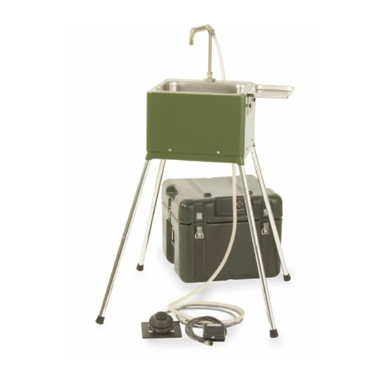
- Page 1 ADU-40CF Portable Field Sink NSN: 6520-01-456-5380 COMMAND AIR OPERATION, MAINTENANCE & SERVICE MANUAL...
-
Page 2: Table Of Contents
TABLE OF CONTENTS Safety Precautions ................2 Introduction . -
Page 3: Introduction
Light weight and compact size make the ADU- 40CF easy to set-up and transport. To receive the best service and longest life from your Aseptico product, follow the instructions detailed in this manual. -
Page 4: Preparation For Installation
Preparations for use and installation instructions After removal from its original packaging, the ADU-40CF will include the following items: Case Contents: Figs A1 & A2 Sink assembly (1) MIL-Spec carry case (1) Operation & Service Manuals (2) Accessory pouches (3) Optional Soap Dispenser pouch (1) Optional Leg Support Kit pouch (1) Figure A1 - Open Case with... -
Page 5: Assembly
Assembly 1. After removing the ADU-40CF Command Air Field Sink from its original packaging, unfasten all perimeter latches and remove the cover. Locate the accessory pouches and lift the sink from the carry case. Refer to Figure A 2. Remove the four collapsible legs from the legs pouch and unfold. Make sure the locking dowel engages completely. -
Page 6: Water Source Information
10. If desired, attach the instrument tray and/or optional soap dispenser to either side of the sink : a) Instrument Tray : Secure the tray with the thumbscrews (Figure I). b) Optional Soap Dispenser (Refer to Figure J): • Position the mounting bracket against the lip of the basin as shown. -
Page 7: Heating System
Heating System The Heating System is composed of the tank, the extendible spout, the tank level sensor, the tilt shutoff sensor, the control circuitry and the heating element. The tank is the reservoir for the water to be heated. The spout position determines the volume of water stored in the tank. The tank level switch, located at the top of the tank, activates the heating element. -
Page 8: Daily Cleaning
6. Drain and disconnect the intake hose. Disinfect all hoses which have come into contact with waste water using a dilute bleach solution. 7. Store the intake, cold water and drain hoses along with the alternate source regulator in the plumbing pouch. -
Page 9: Cleaning And Lubrication
Maintenance and Servicing Instructions Part Numbers and Assembly Details Refer to the included Schematic Drawing Set (PN 421204) for component part numbers and additional service instructions. Cleaning and lubrication The external surfaces of the ADU-40CF’s chassis, spout, basin and accessory tray can be cleaned with a commercial medical/dental disinfectant. -
Page 10: Troubleshooting Chart
Troubleshooting Problem Cause Action Not drawing water, pump operating No water source/intake tube Add water to source/adjust intake hose above water line. Solenoid valve closed Replace Pump seals Replace pump Not drawing water, pump not operating Fuse blown Inspect pump, replace if required Diode Inspect control board, replace components or board as required... -
Page 11: Disassembly, Repair, Replacement
Disassembly, Repair & Replacement Note: The unit should only be powered when it is in the upright position. Operation with the tank tilted at an extreme angle can cause the tilt shutoff sensor to actuate, shutting off the heater. Note: Before beginning any repair, be sure to disconnect the sink from the power source. Access to internal components is gained by removing the spout guide and the sink chassis. -
Page 12: Level Sensor
Replacing the level sensors Tools: 8 in. crescent wrench 1. Trace the electrical leads from the tank level sensor and the tilt shutoff sensor to the control board and remove the sensors' Tank connectors. Note the wiring configuration from the sensors to Level Sensor their connectors. -
Page 13: Solenoid Valve
Replacing the solenoid valve Tools: Pliers, 1/4 socket, 5/64 hex drive or Allen wrench, and 8 in. crescent wrench 1. Remove the snapper type clamp from the end of the solenoid valve by pushing its tabs in opposite directions. Use pliers to improve clamp manipulation. Work the tubing off the end of the valve. 2. - Page 14 NOTES: Page 14...
- Page 15 NOTES: Page 15...
- Page 16 P.O. Box 1548 • Woodinville, WA 98072-1548 1-800-426-5913 • 425-487-3157 • Fax: 360-668-8722 email: info@aseptico.com • Internet: www.aseptico.com P/N 420203 Rev. Q ECO 14703 04/2019...
Need help?
Do you have a question about the ADU-40CF Command Air and is the answer not in the manual?
Questions and answers