
Related Manuals for Aseptico AEU-1000-70V


Summary of Contents for Aseptico AEU-1000-70V
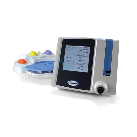
- Page 1 AEU-1000-70V AEU-1000 Dental Implant Motor Systems (AE-70V2)* (AE-7PM)* (AHP-85MB-X)* *Shown with optional equipment purchased separately OPERATION AND MAINTENANCE MANUAL...
- Page 2 AEU-1000-70V / AEU-1000 ! SAFETY PRECAUTIONS Aseptico accepts no liability for direct or consequential injury or dam- s CAUTION: Connect mains power cable to a properly grounded age resulting from improper use, arising in particular through the outlet only. non-observance of the operating instructions, or improper preparation s CAUTION: The motor is sensitive to shock and may be damaged and maintenance of this product.
-
Page 3: Table Of Contents
INTENDED USE . . . . . . . . . . . . . . . . . . . . . . . . . . . . . . .3 Your new Aseptico AEU-1000-70V / AEU-1000 system is one of the finest and most affordable dental implant motor systems available PACKAGE CONTENTS . - Page 4 AEU-1000-70V / AEU-1000 PACKAGE CONTENTS AE-70V2 Foot Controller (AEU-1000-70V only) Power Cord Console AE-7PM Foot Controller (AEU-1000 only) Cradle Irrigation Tubing Set Motor and Cord Spare Peristaltic Tubes Bag Hanger...
-
Page 5: System Setup
AEU-1000-70V / AEU-1000 SYSTEM SETUP Connect the foot controller plug (for either the AE-7PM or AE-70V2 foot controller) to the socket on the back of the This section provides step-by-step instructions for setting up the unit. console. The foot controller plug is “keyed” to the socket and ... - Page 6 AEU-1000-70V / AEU-1000 SYSTEM SETUP (Continued) 10 . Two red arrows on the pump door show the direction to install the irrigation tubing. Start by threading the peristaltic tube segment through the top slot in the pump door. The Place the motor-handpiece onto the cradle ...
- Page 7 AEU-1000-70V / AEU-1000 13 . With one hand, pull the irrigation tube firmly from the bottom 16 . Press the power switch on the rear of the console to the of the pump door . Use the other hand to guide the irriga- on (I) position to turn the unit on.
-
Page 8: Control Panel
AEU-1000-70V / AEU-1000 • RATIO SETTING: Press the number that appears between the CONTROL PANEL and buttons to select the ratio setting: This section describes the functions of the touch-screen. NUMBER DISPLAYED HANDPIECE RATIO SETTING 20:1 Home Screen Press anywhere on the right side of the screen to return to the home screen. -
Page 9: Operation
AEU-1000-70V / AEU-1000 Customizing Presets OPERATION The Preset segment of the screen will flash if you have made any This section explains how to operate the unit using either the AE-70V2 adjustments to the settings of the current preset: or AE-7PM foot controller. -
Page 10: Maintenance And Sterilization
Call Aseptico at 1-800-426-5913 with any questions on sterilization procedures. Handpiece Follow the instructions provided with the handpiece for complete cleaning, maintenance and sterilization instructions. - Page 11 AEU-1000-70V / AEU-1000 STERILIZATION METHODS: Brush off debris from the motor and cord. Thoroughly clean the motor and cord with a moist cloth or Wrapped Sterilization — Place in an appropriately sized steriliza- towel to remove any remaining signs of debris. Avoid pulling tion pouch and seal.
-
Page 12: Messages
Aseptico’s Customer Service Department promptly. Customer Service will provide instructions, usually directing that the product be returned for service. Shipment to Aseptico and the cost thereof is always the responsibility of the purchaser. Accidental misuse, inappropriate installation, or failure to perform directed maintenance voids the warranty. -
Page 13: Fuse Replacement
AEU-1000-70V / AEU-1000 FUSE REPLACEMENT SYMBOL DESCRIPTIONS WARNING Consult Instructions For Use Switch off the power and unplug the unit Type B Equipment before following the steps below. Caution – Consult Accompanying Documents The system features auto-sensing global voltage compatibility. -
Page 14: Specifications
AEU-1000-70V / AEU-1000 SPECIFICATIONS CONSOLE DIMENSIONS: 19.6 cm W x 18.0 cm D x 16.0 cm H (7.72” W x 7.09” D x 6.30” H) CONSOLE WEIGHT: 1.41 kg (3.11 lbs) POWER SOURCE: 100-240V, 50-60Hz CURRENT RATING: 100V/2A, 240V/2A DUTY CYCLE: 16.7% ENVIRONMENTAL CONDITIONS: Operating Temperature: 10°C to 28°C (50°F to 82.4°F) -
Page 15: Custom Presets
AEU-1000-70V / AEU-1000 CUSTOM PRESETS Use the blank tables below to write down your custom preset settings: PRESET DIRECTION SPEED RATIO TORQUE WATER PRST-1 PRST-2 PRST-3 PRST-4 PRST-5 PRST-6 PRST-7 PRST-8 PRESET DIRECTION SPEED RATIO TORQUE WATER PRST-1 PRST-2 PRST-3... - Page 16 P.O. Box 1548, Woodinville, WA 98072 8333 216th Street S.E., Woodinville, WA 98072 Phone (425) 487-3157 • Toll Free (800) 426-5913 Web: www.aseptico.com Email: info@aseptico.com P/N 421100 • Rev. E • ECO 15016 • 06/2020 • Printed in the USA...
Need help?
Do you have a question about the AEU-1000-70V and is the answer not in the manual?
Questions and answers