Aseptico AEU-525CF Transport III Service Manual & Parts List
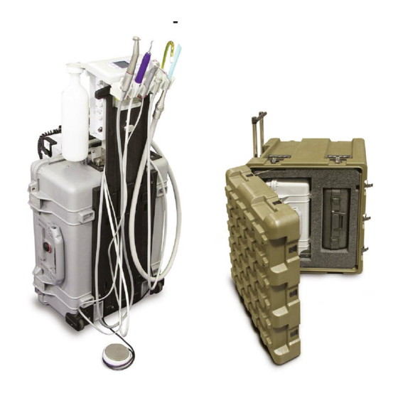
Portable dental system
Hide thumbs
Also See for AEU-525CF Transport III:
- Operation & maintenance manual (32 pages) ,
- Service manual and parts list (36 pages)

Related Manuals for Aseptico AEU-525CF Transport III


Summary of Contents for Aseptico AEU-525CF Transport III
- Page 1 AEU-525CF AEU-525CFH Portable Dental System Transport III SERVICE MANUAL & PARTS LIST...
-
Page 2: Table Of Contents
TABLE OF CONTENTS CONTENTS Page Page PARTS LISTS General Service Information ......1 Inspection & Verification ......1 Figure 112 –... -
Page 3: General Service Information
Vacuum Evacuator (HVE) or low-volume saliva ejector instruments (Fig. 3) are removed from their holders or if they This service and parts manual offers information and parts aren't properly lists not available in the AEU-525CF Transport III Operation Figure 3 SCALER SYRINGE SALIVA... -
Page 4: Cleaning & Lubrication
and water or compressed air. The secondary air filter is a coolant air flows to the handpiece. An air flow adjustment cannister-type filter that threads into the compressor head valve is located next to this ON/OFF toggle valve (Fig. 7). (Fig. -
Page 5: Esd Precautions
Water Lines ESD PRECAUTIONS Disinfect the water lines weekly. Prepare a 1:10 bleach The following electrostatic controls must be used when solution (1 part household bleach to 9 parts water). working on this unit: Remove water supply bottle and discard residual water. ESD Training and Standards: Replace the empty water supply bottle and air purge all Employees handling electronic sub-assemblies and ESD... -
Page 6: Disassembly
-- please return these items to III, hanging from a mounting bracket on the case lid (Fig. 12). Aseptico if repairs are necessary. First, remove the four gray hoses from the top of the waste- The operator control panels are located on the Air/Electric tank lid. -
Page 7: Foot Control
AIR/ELECTRIC MODULE ASSEMBLY customer service- The Air/Electric Module Assembly (PN 330597) is the main able item and should be replaced or returned to Aseptico for control module for the Transport III. It provides the operator repairs, if necessary. controls for the electric motor, scaler, air/water syringe, and two suction valves. -
Page 8: Instrument Holders
DISASSEMBLY - Cont'd blue tube (PN AA-94B) and clear tube (PN AA-94C) from the to remove the two mounting screws (PN 510037). Reassemble the Guard in the reverse order. fittings on the cap. Remove the three mounting screws (PN 510404) from the top of the panel (Fig. 18) with a 3/32" Allen INSTRUMENT HOLDERS wrench and remove cap. -
Page 9: Air/Electric Module Top Panel
Aseptico if repairs are required. Wall and move to work bench. Remove the two Fittings (PN 730062) and gaskets (PN 730074) with a 1/4" open-ended The Control Panel Membrane (PN 420918) is attached to wrench. Use a 9/16" wrench to remove the Toggle Valve... -
Page 10: Manifold Assembly
Board's connectors. Remove Power Board from Module and set aside for reassembly later. IMPORTANT: The Power Board Assembly is not a customer-serviceable item. Return the Board Assembly to Aseptico if repairs are necessary. SCALER DISABLE Pull the inboard Insulator (PN 462113) off the four nylon SWITCH mounting Standoffs (PN 462112) (Fig. - Page 11 Move Block to work bench for further disassembly. Detach (PN 810438) HOLDER remaining sleeve clamps and tubes as necessary. IMPORTANT: The Manifold Block (Fig. 33) is not a customer- serviceable item. Return the Block to Aseptico if repairs are required. Figure 33 JUNCTION BLOCK 1/8" TUBE 1/4"...
-
Page 12: Scaler Control Modules
DISASSEMBLY - Cont'd SCALER CONTROL MODULE Figure 44a Figure 44b Scaler Figure 49 Control Module (PN 730691) is located on the upper left side 12-PIN of the Manifold CONNECTOR BLOCK JUNCTION Module Front BLOCK MOUNTING Wall. Slide the MOUNTING SCREWS (X3) cover of the SCREW At the workbench, use a flat-head screwdriver to remove the... -
Page 13: Electric Motor Receptacle
At the workbench, disconnect the remaining two sleeve SYRINGE AND SYRINGE TUBING clamps and To replace the Syringe (PN TA-90D), remove the two sleeve Figure 52 hoses from CROSS clamps (PN 730015) from the Syringe tube splices located FITTINGS PLUGS PN 730139 inside the bottom panel of the Air &... -
Page 14: Footswitch Connector
Scaler Wand is not a customer-serviceable item. Return the Case, in the upper right-hand corner of the top compartment Wand to Aseptico if repairs are required. (Fig. 64a). Turn the unit off and purge any residual pressure Reassemble the Scaler Wand in the reverse order, adjusting... -
Page 15: Divider Wall
a 5/64" Allen wrench DIVIDER WALL Figure 70 to remove the two The Divider Wall (PN 462000) is located in the top mounting Screws LARGE MTG. CLIP compartment of the Figure 67 (PN 510037) that Transport III Case attach the Baffle to SMALL MTG. -
Page 16: Vacuum Hose Fittings
DISASSEMBLY - Cont’d 510037) that mount the Figure 73 Locate the Cable Tie (PN 510137) that straps the Display Panel to the Compressor. Module Power Figure 77 Remove Panel (see Fig. Cable (PN 875118) 73) and place aside for to the Compressor CABLE reassembly later. -
Page 17: Electrical Panel
Replace the entire Supply connector to the receptacle latch and the pin-position of the or return it to Aseptico if repairs are required. blue wire. Detach the other 2-wire connector from the 'CN1' CONTROL BOARD PCB... -
Page 18: Waste Connector Cable Assembly
Control Board PCB assemblies are not customer COMPRESSOR serviceable. If repairs are required to either assembly, GROUND WIRE replace the entire item or return it to Aseptico for service. WASTE CONNECTOR CABLE ASSEMBLY Locate the Waste Figure 87 MTG SCREW (X2) -
Page 19: Cooling Fan
green/yellow ground wire from the Compressor to the Figure 91 ELECTRICAL PANEL BACK SIDE grounding hardware on the back side of the Electrical Panel, using a 5/16" open ended wrench. Locate the 10-Position Terminal Block (PN 860278) on the back side of the Electrical Panel (Fig. 89). Note the wire colors and terminal positions of the eight wires coming from the Compressor Motor Assembly. -
Page 20: Power Inlet Line Filter (Emi)
DISASSEMBLY - Cont’d At the Voltage Selector Switch, locate the crimp that breakers in place. Use a small flat screwdriver to depress connects the three blue wires together. At the crimp, cut the the locking tabs located on the sides of the Power Entry and single blue wire that leads directly to the Voltage Selector. -
Page 21: Motor Housing - Right Wall Assembly
On the inboard side of the Left Wall Assembly, in the lower open-end wrench to Figure 99 RIGHT WALL ASSEMBLY left-hand corner, locate the red 1/8" Tube (PN AA-94R), detach the nut at the which leads from the Switching Module Manifold Assembly filter end of the (see Fig. -
Page 22: Venturi & Muffler Bracket Assembly
DISASSEMBLY - Cont’d Switching Module Manifold (PN 330594): On the inboard Figure 102 CABLE TIE(S) PRESSURE HOSE FITTING side of the Wall (Fig. 103), use diagonal cutters to pry the SWITCH two 1/8" tube Sleeve Clamps (PN 730015) from the Red ELBOW Tube (PN AA-94R) and Green Tube (PN AA-94G), then the 1/4"... -
Page 23: Compressor/Vacuum Pump Assembly
open-end wrench to remove the 1/4" hose fittings. The 1/2" hoses can be pryed off their fittings by hand. IMPORTANT: Disassembly of the Venturi & Muffler Bracket Assembly is not recommended unless component Venturi/Muffler Assemblies #1 & #2: Use a 3/32" Allen malfunction or breakage occurs. -
Page 24: Motor Mount Assembly
Allen wrench to remove the 1/4" Plugs (PN 730098) from the DOOR Compressor Heads. FASTENERS (X2) IMPORTANT: The Compressor Motor is not a customer- serviceable item. Return the Motor to Aseptico if repairs are required. LOCK BLOCK MOUNTING SCREWS (X3) MOTOR MOUNT ASSEMBLY... - Page 25 Washer (PN 510445) with a Phillips screwdriver and detach THIS COMPLETES THE DISASSEMBLY PROCEDURE Tool from Case, if necessary. FOR THE AEU-525CF TRANSPORT III SYSTEM. Locate the Case Vent Door (PN 462004) on the outboard side of the Lid (see Figs. 109 & 110). Unlock the four Door Fasteners (PN 510772) and swing the Door open to expose the two Hinges (PN 462005) and Hinge Stop (PN 510777).
- Page 26 NUT NYLOC 10-32 STNLS 510124 FOOT BUMPER .5 X .14 CYLIN CLEAR 850067 WASHER FLAT STNLS #10 510356 FTN 1/8 ID SLEEVE CLAMP CLEAR 730015 LABEL ASEPTICO 420981 TUBING POLY 1/8OD GRN AA-94G 2.1458 CASE SILVER MACHINED AEU-525 410201-08 TUBING POLY 1/8OD RED AA-94R 3.375...
- Page 27 FINAL ASSEMBLY PARTS LIST - Figure 112 (Sheet 2 of 9) AIR/ELECTRIC MODULE ASSEMBLY SEE FIG. 113, PAGE 33 WASTE TANK ASSEMBLY (NO COMPONENT BREAKDOWN) NOTE: Refer to Page 24 for Parts Descriptions Page 25...
- Page 28 FINAL ASSEMBLY PARTS LIST - Figure 112 (Sheet 3 of 9) AIR BOTTLE ASSEMBLY SEE FIG. 114, PAGE 37 NOTE: Refer to Page 24 for Parts Descriptions Page 26...
- Page 29 FINAL ASSEMBLY PARTS LIST - Figure 112 (Sheet 4 of 9) COMPRESSOR ASSEMBLY SEE FIG. 115, PAGE 38 NOTE: Refer to Page 24 for Parts Descriptions Page 27...
- Page 30 FINAL ASSEMBLY PARTS LIST - Figure 112 (Sheet 5 of 9) NOTE: Refer to Page 24 for Parts Descriptions Page 28...
- Page 31 FINAL ASSEMBLY PARTS LIST - Figure 112 (Sheet 6 of 9) AIR BOTTLE ASSEMBLY SEE FIG. 114, PAGE 37 NOTE: Refer to Page 24 for Parts Descriptions Page 29...
- Page 32 FINAL ASSEMBLY PARTS LIST - Figure 112 (Sheet 7 of 9) NOTE: Refer to Page 24 for Parts Descriptions Page 30...
- Page 33 FINAL ASSEMBLY PARTS LIST - Figure 112 (Sheet 8 of 9) NOTE: Refer to Page 24 for Parts Descriptions Page 31...
- Page 34 FINAL ASSEMBLY PARTS LIST - Figure 112 (Sheet 9 of 9) NOTE: Refer to Page 24 for Parts Descriptions Page 32...
- Page 35 AIR/ELECTRIC MODULE ASSEMBLY - Figure 113 (Sheet 1 of 4 ) ITEM PART NO ITEM PART NO AIR/ELECTRIC SCALER W/LED MODULE ASSY 525 330597 TAPE FOAM ACRYLIC 3M VHB 1/2 WIDE ROLL BLK 490145 0.009 SCALER ASSEMBLY SYSTEM WITH LED LIGHT 730691 DELIVERY MODULE REAR WALL AEU-525 462037...
- Page 36 AIR/ELECTRIC MODULE ASSEMBLY - Figure 113 (Sheet 2 of 4) NOTE: Refer to Page 33 for Parts Descriptions Page 34...
- Page 37 AIR/ELECTRIC MODULE ASSEMBLY - Figure 113 (Sheet 3 of 4) NOTE: Refer to Page 33 for Parts Descriptions Page 35...
- Page 38 AIR/ELECTRIC MODULE ASSEMBLY - Figure 113 (Sheet 4 of 4) MANIFOLD ASSEMBLY (NO COMPONENT BREAKDOWN) NOTE: Refer to Page 33 for Parts Descriptions Page 36...
- Page 39 PARTS LIST - Figure 114 - Air Bottle Assembly ITEM PART NO ITEM PART NO BOTTLE 750ML (25OZ) BLOW MOLDED HDPE 730657 FTN ELBOW 90 1/4 POLY X 1/8 MPT 730120 LABEL MYLAR AEU-425 AIR 420307 FTN 1/4 POLY X 1/8 MPT POLYTITE 730117 GASKET FOR NWS-8 BOTTLE LID 730473...
- Page 40 PARTS LIST - Figure 115 - Compressor Assembly ITEM PART NO ITEM PART NO CLAMP HOSE SNAPPER .616 TO .707 GRIP 510425 TUBING 1/2 OD X .062 WALL GREY URETHANE 730373 0.8333 TUBING AA-24 1/2 X 1/8 GRAY AA-259 3.6458 TUBING SALIVA EJECT 3/8OD GRY AA-86G 6.0625...
- Page 41 ELECTRICAL PANEL ASSEMBLY - Figure 116 (Sheet 1 of 2) ITEM PART NO ITEM PART NO WIRE PVC #18 WHT (9) 870031 3.525 PWR ENTRY/CKT BRKR/SWTCH 6A 2-POLE 1.5MM 840119 TERM FEMALE .250 X .032 22-18 AWG RED 860240 GROMMET 1/4 DIA FOR 3/8 DIA X .095 NEOPRENE 870185 TERMINAL BLIND END CRIMP 4X#18-2X#12 860287 FAN 115 V TUBEAXIAL 106 CFM 4.69 SQ X 1.5 THK 540012...
- Page 42 ELECTRICAL PANEL ASSEMBLY - Figure 116 (Sheet 2 of 2) NOTE: Refer to Page 39 for Parts Descriptions Page 40...
- Page 43 PARTS LIST - Figure 117 - Motor Housing - Left Wall Assembly ITEM PART NO ITEM PART NO TOP VACUUM VALVE AEU-525 462090 M/S STNLS PHDPHL 6-32 X 1-3/4 510618 C/S BTNSOC STNLS 6-32 X 3/8 510160 O-RING 0.487 ID X 0.103 WIDE 520079 O-RING 0.489 ID X 0.070 WIDE VITON 60 DUROM 520078...
- Page 44 PARTS LIST - Figure 118 - Motor Housing - Right Wall Assembly ITEM PART NO ITEM PART NO WIRE PVC #22 BLK (0) 870042 GASKET NYLON #10 730074 TERM FEMALE .250 X .032 22-18 AWG RED 860240 FTN ELBOW 90 1/4 POLY X 1/8 MPT 730120 FTN 1/8 ID SLEEVE CLAMP CLEAR 730015...
- Page 45 PARTS LIST - Figure 119 - Venturi & Muffler Bracket Assembly ITEM PART NO ITEM PART NO CABLE ASSY UNLOADER PRESSURE SWITCH 875120 C/S BTNSOC STNLS 8-32 X 1/4 510309 TUBING POLY 1/4ODX.159ID GRY 90 DURO AA-95G GASKET NYLON #10 730074 TIE WRAP 8 IN X 18# NYLON 510628...
- Page 46 PARTS LIST - Figure 120 - Compressor/Vacuum Pump Assembly ITEM PART NO ITEM PART NO COLD START VALVE ASSY 1/4 MPT 330633 TERM FEMALE .250 X .032 22-18 AWG RED 860240 MOTOR MOUNT AEU-525 462082 HEAT SHRINK 1/4 BLK 870120 C/S BTNSOC STNLS 1/4-20 X 1-1/4 510295 FTN ELBOW 90 1/4 POLY X 1/8 MPT...
- Page 47 PARTS LIST - Figure 121 - Inlet/Outlet Air Filter Assembly ITEM PART NO ITEM PART NO MEMBRANE INLET POWER COVER AEU-525CF 462298 ASSY INLET/OUTLET FILTER AEU-525CF 330634 PLATE CLAMP WASTE MEMBRANE AEU-525CF 462316 FOAM FILTER OUTER AEU-525CF 730685 MEMBRANE WASTE SENSOR COVER AEU-525CF 462299 FOAM FILTER INNER AEU-525CF 730684...
-
Page 48: Sterilization & Maintenance
STERILIZATION AND MAINTENANCE: Because of its simple design, the Aseptico AEU-525CF MOTOR LED LENS CLEANING: The lens of the LED light on the motor (see Fig. 124) is soft Transport III System requires very little maintenance. Any maintenance that is needed can be performed in minutes. - Page 49 AIR BOTTLE FILTER: ULTRASONIC SCALER: Routinely check the air bottle filter once a day for The scaler handpiece cover and scaler tips are fully condensation. To drain condensa-tion, place a towel or autoclavable. Disinfect and clean the cover and tips before container below the filter and use pliers to carefully loosen autoclaving.
-
Page 50: Troubleshooting Guide
TROUBLESHOOTING: Correction: • Check system power connection. • Check if both circuit breaker switches are On. • Check if waste container sensor is connected. • Check if waste container is full. • Check source circuit to see if it is a minimum of 15A. •... -
Page 51: Replacement Parts List
REPLACEMENT PARTS LIST ITEM PART NO ITEM PART NO WASTE TANK ASSEMBLY AEU-525 330603 BOTTLE 750 ML (25 OZ) BLOW MOLDED HDPE (AIR) 730657 INLINE STRAINER WASTE CONTAINER (HVE 462124 LINECORD REMOTE US 10 FT HOSP GREY 15A/125A 840049 O-RING .125ID X .070CS VT70 (AIR-JUNCTION) 520025 LINECORD REMOTE EURO BLACK 2.5 M 840007... -
Page 52: Final Inspection & Testing
FINAL INSPECTION AND TESTING - Procedure for Aseptico AEU-525CF - F-4.10-02-B bottle cap. Switch to ‘Purge’ and replace the water (Testing specs subject to change. Refer to latest Schematic Drawing Set, PN 420991, Sheets 16-18 for updates.) bottle. EXAMINATION FOR DEFECTS: C. - Page 53 preset number stops flashing. Now press the footpedal F. Performance Test (Syringe): to turn on the motor and LED and then release it and 1. Fill the water bottle and turn on the compressor to fill verify that the LED remains on for 20 +/-5 seconds. the air reservoir.
-
Page 54: Final Inspection & Testing
FINAL INSPECTION AND TESTING - Cont’d Test Details: 6. Dielectric Withstand Test - Mains to the combined foot pedal wires. a. Connect the power cord from the test equipment to Test parameters: Test voltage 4350 VDC, Ramp 1 the mains power inlet of the AEU-525, and the return second, Dwell 1 second, Leakage limit 1 mA, Arc Fail is lead of the Ground Bond Tester to the chrome plated OFF. -
Page 55: Symbol Definitions
SYMBOL DEFINITIONS: High Volume Evacuator (HVE) Type BF Equipment Attention, consult accompanying documents Pressure Gauge Motor Direction Consult Instructions For Use Light Controls Manufacturer Footswitch Dangerous Voltage On/Off Switch - Mains Alternating current Atmospheric Pressure Limitation Temperature Limitation Water Counterclockwise to Increase/Open Humidity Limitation Clockwise to Decrease/Close Electric Handpiece... -
Page 56: Required Tools List
REQUIRED TOOLS LIST Allen Wrenches: Screwdrivers: 1/16" 1/4" Standard, Slot 5/64" 3/64" Standard Slot (Jeweler's) 3/32" #1 Phillips 1/8" #2 Phillips 9/64" Electrical Tools: 5/32" Wire Stripper Crimp Tool 3/16" Panduit Model CT-1551 (or equivalent) 1/4" Molex 640014100 (or equivalent) Diagonal Cutters Combination Wrenches: 1/4"... -
Page 57: Specifications
SPECIFICATIONS Transport III Case Size: ..17.93” W x 22.06” L x 10.43” H (45.5 cm x 56 cm x 26.5 cm) Shipping Case Size: ..30.5” W x 25.75” L x 24.75” H (77.47 cm x 65.40 cm x 62.86 cm) 525CF Weight (fully loaded): .57 lbs (25.8 kg) Shipping Case Weight: . -
Page 58: Warranty
Other handpieces and repair. If the product is not covered under warranty, Aseptico expendable components, such as air turbines and light offers Repair Services for a fee. -
Page 59: Notes
Notes Page 57... - Page 60 For Further Service And/Or Technical Assistance Contact: P.O. Box 1548 • Woodinville, WA 98072-1548 1-800-426-5913 • 425-487-3157 • Fax: 425-487-2608 www.aseptico.com • info@aseptico.com P/N: 420990 Rev. G ECO 14684 PRINTED IN THE USA 03/2019...
Need help?
Do you have a question about the AEU-525CF Transport III and is the answer not in the manual?
Questions and answers