Aseptico ADU-20B CompriCart II Operation And Maintenance Instruction Manual
Hide thumbs
Also See for ADU-20B CompriCart II:
- Operation and maintenance instruction manual (12 pages)
Advertisement
Quick Links
Advertisement

Subscribe to Our Youtube Channel
Related Manuals for Aseptico ADU-20B CompriCart II


Summary of Contents for Aseptico ADU-20B CompriCart II
- Page 1 OPERATION and MAINTENANCE INSTRUCTION MANUAL ADU-20B CompriCart II...
- Page 2 8333 216th Street SE • Woodinville, WA 98072 (425) 487-3157 • (800) 426-5913 • Figure 2 - Air Supply Connector ........3 www.aseptico.com • info@aseptico.com • Figure 3 HVE Vacuum Assembly ........3 • Figure 4 Saliva Ejector Assembly ........4 To prevent injury to people and damage to property, •...
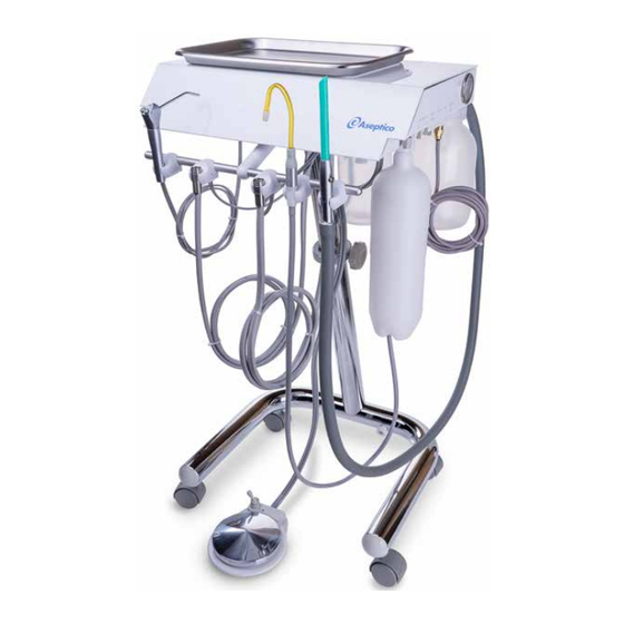
- Page 3 The system is designed for portable operatory use and features Place the ADU-20B CompriCart II in an upright position on a a three-way air/water syringe, automatic highspeed and flat, stable surface. Loosen the center column retaining knob lowspeed handpiece controls, high volume evacuator and saliva and extend the telescoping upper portion.
- Page 4 Figure 5 HANDPIECE CONTROLS (Fig. 7) - The Aseptico ADU-20B includes two handpieces mounted to the front bar. These are fully automatic. When a handpiece is removed from it’s holder, pressure is automatically opened and ready for use with foot control.
- Page 5 Pressure Gauge activate Handpiece Water Coolant Flow Control Figure 8 - Foot Control WATER SUPPLY TANK - The Aseptico ADU-20B Air Supply incorporates a self contained pressurized water system (Fig. Line 9). This consists of a 2-liter HDPE tank dispensing water...
- Page 6 Syringe Figure 12 - Saliva Ejector Assembly Water Flow Adjustment Vacuum Screw Hose Quick Disconnect Syringe Waste Container Air Flow Quick Disconnect FRONT OF Adjustment CART Screw Figure 14 - Syringe Flow Adj. Assembly Salive Ejector SYRINGE AIR/WATER FLOW ADJUSTMENT (Fig. 14) Valve - The syringe flow adjustment block is located inside the delivery head near the left rear corner and has two slotted...
- Page 7 (90) days from the date of return to Aseptico, whichever is later. This limited warranty applies only to the initial or first installation of the WATER LINES - Disinfect the water lines weekly.
- Page 8 P.O. Box 1548 • Woodinville, WA 98072 8333 216th Street SE • Woodinville, WA 98072 (425) 487-3157 • (800) 426-5913 www.aseptico.com • info@aseptico.com P/N: 420366 Rev. O ECO 15499 PRINTED IN THE 04/2022 U.S.A.
Need help?
Do you have a question about the ADU-20B CompriCart II and is the answer not in the manual?
Questions and answers