
Related Manuals for Elektro-Automatik PS 9000 T Series


Summary of Contents for Elektro-Automatik PS 9000 T Series
- Page 1 Operating Guide PS 9000 T DC Laboratory Power Supply Doc ID: PS9TEN Revision: 01 Date: 04/2017...
-
Page 3: Table Of Contents
PS 9000 T Series TABLE OF CONTENTS GENERAL OPERATION AND APPLICATION About this document ........4 Personal safety ..........34 1.1.1 Retention and use ..........4 Operating modes .........34 1.1.2 Copyright ............4 3.2.1 Voltage regulation / Constant voltage ..34 1.1.3 Validity ............4 3.2.2 Current regulation / constant current / current 1.1.4... -
Page 4: About This Document
EA Elektro-Automatik guarantees the functional competence of the applied technology and the stated performance parameters. The warranty period begins with the delivery of free from defects equipment. Terms of guarantee are included in the general terms and conditions (TOS) of EA Elektro-Automatik. Limitation of liability All statements and instructions in this manual are based on current norms and regulations, up-to-date technology and our long term knowledge and experience. -
Page 5: Disposal Of Equipment
PS 9000 T Series Disposal of equipment A piece of equipment which is intended for disposal must, according to European laws and regulations (ElektroG, WEEE) be returned to the manufacturer for scrapping, unless the person operating the piece of equipment or an- other, delegated person is conducting the disposal. -
Page 6: Safety
PS 9000 T Series Safety 1.7.1 Safety notices Mortal danger - Hazardous voltage • Electrical equipment operation means that some parts can be under dangerous voltage. Therefore all parts under voltage must be covered! This basically applies to all models, though 40 V models according to SELV can not generate hazardous DC voltage. -
Page 7: Responsibility Of The Operator
PS 9000 T Series 1.7.3 Responsibility of the operator Operator is any natural or legal person who uses the equipment or delegates the usage to a third party, and is responsible during its usage for the safety of the user, other personnel or third parties. -
Page 8: Alarm Signals
PS 9000 T Series 1.7.5 Alarm signals The equipment offers various possibilities for signalling alarm conditions, however, not for danger situations. They are signalled optically (on the display as text) and electronically (pin/status output of an analog interface) and digitally (digital interface). All alarms will cause the device to switch off the DC output. -
Page 9: Specific Technical Data
PS 9000 T Series 1.8.3 Specific technical data Model 320 W PS 9040-20 T PS 9080-10 T PS 9200-04 T AC Input Voltage range 90...264 V AC 90...264 V AC 90...264 V AC Connection 1ph,N,PE 1ph,N,PE 1ph,N,PE Frequency 45-65 Hz... - Page 10 PS 9000 T Series Model 320 W PS 9040-20 T PS 9080-10 T PS 9200-04 T Power regulation Display: Resolution See section „1.9.5.4. Resolution of the displayed values“ Display: Accuracy ≤ 0.8% P ≤ 0.8% P ≤ 0.8% P Efficiency ~ 92% ~ 92% ~ 93%...
- Page 11 PS 9000 T Series Model 640 W PS 9040-40 T PS 9080-20 T PS 9200-10 T AC Input Voltage range 90...264 V AC 90...264 V AC 90...264 V AC Connection 1ph,N,PE 1ph,N,PE 1ph,N,PE Frequency 45-65 Hz 45-65 Hz 45-65 Hz...
- Page 12 PS 9000 T Series Model 640 W PS 9040-40 T PS 9080-20 T PS 9200-10 T Power regulation Display: Resolution See section „1.9.5.4. Resolution of the displayed values“ Display: Accuracy ≤ 0.8% P ≤ 0.8% P ≤ 0.8% P Efficiency ~ 92% ~ 92% ~ 93%...
- Page 13 PS 9000 T Series Model 1000 W PS 9040-40 T PS 9080-40 T PS 9200-15 T AC Input Voltage range 90...264 V AC 90...264 V AC 90...264 V AC Connection 1ph,N,PE 1ph,N,PE 1ph,N,PE Frequency 45-65 Hz 45-65 Hz 45-65 Hz...
- Page 14 PS 9000 T Series Model 1000 W PS 9040-40 T PS 9080-40 T PS 9200-15 T Power regulation Display: Resolution See section „1.9.5.4. Resolution of the displayed values“ Display: Accuracy ≤ 0.8% P ≤ 0.8% P ≤ 0.8% P Efficiency ~ 92% ~ 92% ~ 92%...
- Page 15 PS 9000 T Series Model 1000 / 1500 W PS 9500-06 T PS 9040-60 T PS 9080-60 T AC Input Voltage range without derating 90...264 V AC 150...264 V AC 150...264 V AC Voltage range with derating 90...150 V AC 90...150 V AC...
- Page 16 PS 9000 T Series Model 1000 / 1500 W PS 9500-06 T PS 9040-60 T PS 9080-60 T Power regulation Display: Resolution See section „1.9.5.4. Resolution of the displayed values“ Display: Accuracy ≤ 0.8% P ≤ 0.8% P ≤ 0.8% P Efficiency ~ 93% ~ 92%...
- Page 17 PS 9000 T Series Model 1500 W PS 9200-25 T PS 9500-10 T AC Input Voltage range without derating 150...264 V AC 150...264 V AC Voltage range with derating 90...150 V AC 90...150 V AC Connection 1ph,N,PE 1ph,N,PE Frequency 45-65 Hz...
- Page 18 PS 9000 T Series Model 1500 W PS 9200-25 T PS 9500-10 T Power regulation Display: Resolution See section „1.9.5.4. Resolution of the displayed values“ Display: Accuracy ≤ 0.8% P ≤ 0.8% P Efficiency ~ 92% ~ 92% Analog interface (optional) Set value inputs...
-
Page 19: Views
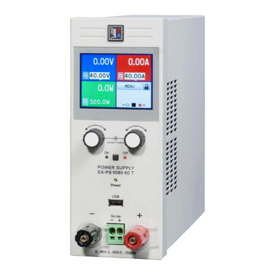
PS 9000 T Series 1.8.4 Views A - Control panel with display B - Knobs C - USB port D - DC output E - Remote sensing connector Figure 1 - Front view EA Elektro-Automatik GmbH Fon: +49 2162 / 3785-0 www.elektroautomatik.de Page 19 Helmholtzstr. - Page 20 PS 9000 T Series Figure 2 - Rear view (320 W / 640 W version shown) Figure 3 - Rear view (1000 W / 1500 W version shown) F - Control interfaces (digital, analog) * J - Power switch G - Exhaust...
- Page 21 PS 9000 T Series Figure 4 - Top view EA Elektro-Automatik GmbH Fon: +49 2162 / 3785-0 www.elektroautomatik.de Page 21 Helmholtzstr. 31-33 • 41747 Viersen Fax: +49 2162 / 16230 ea1974@elektroautomatik.de Germany...
- Page 22 PS 9000 T Series Overview of the elements of the operating panel For a detailed description see section „1.9.5. The control panel (HMI)“. Touchscreen display Used for selection of set values, menus, condi- tions and display of actual values and status.
-
Page 23: Construction And Function
General description The DC laboratory power supplies of the PS 9000 T series are especially suitable for the use in test and develop- ment applications, in laboratories and research. The “T” in the series names stands for tower and point for the upright enclosure design which saves space on laboratory desks and test equipment racks. -
Page 24: Scope Of Delivery
PS 9000 T Series 1.9.3 Scope of delivery 1 x Power supply device PS 9000 T 1 x Mains cord 2 m (1000/1500 W models) or 1.5 m (320/640 W models) with Schuko plug or UK plug, depending on shipping destination 1 x USB cable, 1.8 m 1 x USB stick with software and documentation 1.9.4 Optional accessories The below listed optional accessories can be purchased separately from the device and can be installed by the user:... -
Page 25: The Control Panel (Hmi)
PS 9000 T Series 1.9.5 The control panel (HMI) The HMI (Human Machine Interface) consists of a display with touchscreen, two rotary knobs, a pushbutton and a USB-A port. 1.9.5.1 Touchscreen display The graphic touchscreen display is divided into a number of areas. The complete display is touch sensitive and can be operated by finger or stylus to control the equipment. - Page 26 PS 9000 T Series • Status display (upper right) This area displays various status texts and symbols: Display Description Locked The HMI is locked Unlocked The HMI is unlocked Remote: The device is under remote control from..Analog ..the built-in analog interface ..the built-in USB port...
-
Page 27: Usb Port (Back Side)
The driver is delivered on the included USB stick and installs a virtual COM port. Details for remote control can be found on the included USB stick or the web site of Elektro-Automatik. The device can be addressed via this port either using the international standard ModBus protocol or by SCPI language. -
Page 28: Ethernet Port
PS 9000 T Series 1.9.8 Ethernet port The Ethernet port is optional. Also see section 1.9.4. The port on the back side of the device is provided for com- munication with the device in terms of remote control or moni- toring. -
Page 29: Installation & Commissioning
Preparation Mains connection for a PS 9000 T series device is done via the included 1.5 meters or 2 meters long (depending on the power rating and input current) three-pole mains cord. In case a different AC connection is used, make sure that the other cable has at least a cross section suitable for the rated input current (stated on type label). - Page 30 PS 9000 T Series 2.3.3.1 Placement on horizontal standing surfaces The device is designed as a desktop unit and must only be operated on horizontal surfaces, which are capable of securely carrying the weight of the device. Acceptable and inacceptable operating positions:...
-
Page 31: Connection To Dc Loads
PS 9000 T Series 2.3.4 Connection to DC loads • Connection to and operation with transformerless DC-AC inverters (for example solar in- verters) is restricted, because the inverter can shift the potential of negative output (DC-) against PE (ground), which is limited to max. ±400 V DC. -
Page 32: Connection Of Remote Sensing
PS 9000 T Series 2.3.6 Connection of remote sensing • Remote sensing is only effective during constant voltage operation (CV) and for other regulation modes the sense input should be disconnected, if possible, because connecting it generally increases the oscillation tendency. -
Page 33: Initial Commission
PS 9000 T Series 2.3.8.3 Alternative drivers In case the CDC drivers described above are not available on your system, or for some reason do not function correctly, commercial suppliers can help. Search the Internet for suppliers using the keywords “cdc driver windows“... -
Page 34: Operation And Application
PS 9000 T Series Operation and application Personal safety • In order to guarantee safety when using the device, it is essential that only persons operate the device who are fully acquainted and trained in the required safety measures to be taken when working with dangerous electrical voltages • For models which can generate a voltage which is dangerous by contact, or is connected to... -
Page 35: Current Regulation / Constant Current / Current Limiting
PS 9000 T Series 3.2.2 Current regulation / constant current / current limiting Current regulation is also known as current limiting or constant current mode (CC). The DC output current is held constant by the power supply, once the output current to the load reaches the adjusted limit. Then the power supply automatically switches The current flowing from the power supply is determined by the... -
Page 36: Alarm Conditions
PS 9000 T Series Alarm conditions This section only gives an overview about device alarms. What to do in case your device indi- cates an alarm condition is described in section „3.6. Alarms and monitoring“. As a basic principle, all alarm conditions are signalled optically (text + message in the display) and as a readable status and alarm counter via the digital interface. -
Page 37: Manual Operation
PS 9000 T Series Manual operation 3.4.1 Switching on the device The device should, as far as possible, always be switched on using the toggle switch on the rear of the device. After switching on, the display will first show the company logo, followed by a language selection which will close automatically after 3 seconds and later manufacturer’s name and address, device type, firmware version(s), serial number and item number. - Page 38 PS 9000 T Series EA Elektro-Automatik GmbH Fon: +49 2162 / 3785-0 www.elektroautomatik.de Page 38 Helmholtzstr. 31-33 • 41747 Viersen Fax: +49 2162 / 16230 ea1974@elektroautomatik.de Germany...
- Page 39 PS 9000 T Series EA Elektro-Automatik GmbH Fon: +49 2162 / 3785-0 www.elektroautomatik.de Page 39 Helmholtzstr. 31-33 • 41747 Viersen Fax: +49 2162 / 16230 ea1974@elektroautomatik.de Germany...
- Page 40 PS 9000 T Series EA Elektro-Automatik GmbH Fon: +49 2162 / 3785-0 www.elektroautomatik.de Page 40 Helmholtzstr. 31-33 • 41747 Viersen Fax: +49 2162 / 16230 ea1974@elektroautomatik.de Germany...
- Page 41 PS 9000 T Series 3.4.3.1 Menu “Settings” This is main menu for all settings related to the general operation of the device and of the interface(s). Sub menu P. Description Output Settings Allows for adjustment of set values related to the DC output, alternatively to the...
- Page 42 PS 9000 T Series Setting P. Description Analog interface Rem-SB Selects how the input pin “Rem-SB” of the analog interface shall be working regarding levels (see „3.5.4.4 Analog interface specification“ on page 51) and logic: • normal = Levels and function as described in the table in 3.5.4.4 • inverted = Levels and function will be inverted...
- Page 43 PS 9000 T Series Submenu “IP Settings 2” Element Description DNS address Default value: 0.0.0.0 Permanent manual setting of the network address of a domain name server (short: DNS) which has to be present in order to translate the host name to the device’s IP, so the device...
- Page 44 PS 9000 T Series 3.4.3.7 Menu “HMI Setup” These settings refer exclusively to the control panel (HMI). Element Description Language Selection of the display language between German, English, Russian or Chinese. This selection screen is also shown for 3 seconds during the startup phase of the device.
-
Page 45: Adjustment Limits (Limits)
PS 9000 T Series 3.4.4 Adjustment limits (Limits) Adjustment limits are only effective on the related set values, no matter if using manual adjustment or remote control setting! The limits settings could be locked by a PIN (see MENU, “Limits lock”) Defaults are that all set values (U, I, P) are adjustable from 0 to 100%. - Page 46 PS 9000 T Series ► How to adjust values with the rotary knobs First check if the value you want to change is already assigned to one of the rotary knobs. The main screen displays the assignment with the two assigned set values being inverted.
-
Page 47: Switching The Main Screen View
PS 9000 T Series 3.4.6 Switching the main screen view The main screen, also called status page, with its set values, actual values and device status can be switched from the standard view mode with three or four values to a simpler mode with only voltage and current display. -
Page 48: Recording To Usb Stick (Logging)
PS 9000 T Series 3.4.8 Recording to USB stick (logging) Device data can be recorded to USB stick (2.0, 3.0, not all vendors supported) anytime. For specifications of the USB stick and the generated log files refer to section „1.9.5.5. USB-Port (Front side)“. The logging stores files of CSV format on the stick. The layout of the log data is the same as when logging via PC with software EA Power Control. The advantage of USB logging over PC logging is the mobility and that no PC is required. The logging feature just has to be activated and configured in the MENU. 3.4.8.1 Configuration Also see section 3.4.3.6. -
Page 49: Remote Control
Programming details for the interfaces, the communication protocols etc. are to be found in the documentation “Programming Guide ModBus & SCPI“ which is supplied on the included USB stick or which is available as down- load from the EA Elektro-Automatik website. EA Elektro-Automatik GmbH Fon: +49 2162 / 3785-0 www.elektroautomatik.de... -
Page 50: Remote Control Via The Analog Interface (Ai)
PS 9000 T Series 3.5.4 Remote control via the analog interface (AI) 3.5.4.1 General The optionally available, galvanically isolated, 15-pole analog interface (short: AI, also see section 1.9.9) is located on the back side of the device after installation and offers the following possibilities: • Remote control of current, voltage and power... - Page 51 PS 9000 T Series 3.5.4.3 Acknowledging device alarms Device alarms (see 3.6.1) are always indicated in the front display and some of them are also reported as signal on the analog interface socket (see 3.5.4.4), for example the overvoltage alarm (OV), which is considered as critical.
- Page 52 PS 9000 T Series 3.5.4.5 Overview of the Sub-D Socket 3.5.4.6 Simplified diagram of the pins Digital Input (DI) Analog Input (AI) V~0.5 It requires to use a switch with low resist- High resistance input (impedance ance (relay, switch, circuit breaker etc.) in >40 k...
- Page 53 PS 9000 T Series • Remote control is not active In this mode of operation pin “REM-SB” can serve as lock, preventing the DC output from being switched on by any means. This results in following possible situations: Parameter Behaviour output „REM-SB“...
-
Page 54: Alarms And Monitoring
PS 9000 T Series Alarms and monitoring 3.6.1 Device alarm handling A device alarm incident will usually lead to DC output switch-off. Some alarms must be acknowledged (see below), which can only happen if the cause of the alarm is not persistent anymore. Other alarms acknowledge themselves if the cause has vanished, like the OT and the PF alarm. -
Page 55: Control Panel (Hmi) Lock
PS 9000 T Series Control panel (HMI) lock In order to avoid the accidental alteration of a value during manual operation, the rotary knobs or the touchscreen can be locked so that no alteration of values will be accepted without prior unlocking. -
Page 56: Loading And Saving A User Profile
PS 9000 T Series Loading and saving a user profile The menu “Profiles” serves to select between a default profile and up to 5 user profiles. A profile is a collection of all settings and set values. Upon delivery, or after a reset, all 6 profiles have the same settings and all set values are 0. If the user changes settings or sets target values then these create a working profile which can be saved to one of the 5 user profiles. These profiles or the default one can then be switched. The default profile is read-only. The purpose of a profile is to load a set of set values, settings limits and monitoring thresholds quickly without having to readjust these. As all HMI settings are saved in the profile, including language, a profile change can also be accompanied by a change in HMI language. On calling up the menu page and selecting a profile the most important settings can be seen, but not changed. ► How to save the current values and settings (working profile) as a user profile... -
Page 57: Other Applications
PS 9000 T Series 3.10 Other applications 3.10.1 Series connection Series connection of two or multiple devices is basically possible, but for reasons of safety and isolation following restrictions apply: • Both, negative (DC-) and positive (DC+) output poles are coupled to PE via type X capacitors, limiting the max. -
Page 58: Service And Maintenance
PS 9000 T Series Service and maintenance Maintenance / cleaning The device needs no maintenance. Cleaning may be needed for the internal fan, the frequency of cleanse is depending on the ambient conditions. The fan serves to cool the components which are heated by the inherent power loss. A heavily dirt filled fan can lead to insufficient airflow and therefore the DC output would switch off too... -
Page 59: Calibration
PS 9000 T Series Calibration 4.3.1 Preface The devices of series PS 9000 T feature a function to readjust the most important output values when doing a calibration and in case these values have moved out of tolerance. The readjustment is limited to compensate small differences of up to 1% or 2% of the max. - Page 60 PS 9000 T Series 4.3.3.1 Set values ► How to calibrate the voltage Connect a multimeter to the DC output. Connect a load and set its cur- rent to approx. 5% of the nominal current of the power supply, in this example ~3 A, and 0 V (if the load is electronic).
-
Page 61: Contact And Support
PS 9000 T Series 4.3.3.3 Save and exit After calibration you may furthermore enter the current date as “calibration date” by tapping in the selection screen and enter the date in format YYYY / MM / DD. Last but not least save the calibration data permanently by tapping Leaving the calibration selection menu without tapping “Save and exit”... - Page 64 EA-Elektro-Automatik GmbH & Co. KG Development - Production - Sales Helmholtzstraße 31-37 41747 Viersen Germany Fon: +49 2162 37 850 Fax: +49 02162 16 230 ea1974@elektroautomatik.de www.elektroautomatik.de...
Need help?
Do you have a question about the PS 9000 T Series and is the answer not in the manual?
Questions and answers