Table of Contents
Advertisement
Operating Guide
PS 9000 2U
DC Laboratory Power Supply
Attention! This document is only
valid for devices color display
and with firmware "KE: 3.04"
(standard models) or "KE: 2.05"
(GPIB models) and "HMI: 2.02"
or higher. For availability of up-
dates for your device check our
website or contact us.
Doc ID: PS92TEN
Revision: 08
Date: 04/2018
Advertisement
Table of Contents

Related Manuals for Elektro-Automatik PS 9040-40 2U


Summary of Contents for Elektro-Automatik PS 9040-40 2U
- Page 1 Operating Guide PS 9000 2U DC Laboratory Power Supply Attention! This document is only valid for devices color display and with firmware “KE: 3.04” (standard models) or “KE: 2.05” (GPIB models) and “HMI: 2.02” Doc ID: PS92TEN or higher. For availability of up- dates for your device check our Revision: 08 website or contact us.
-
Page 3: Table Of Contents
3.9.4 Two quadrants operation (2QO) ....60 2.3.5 Connection to DC loads .......34 2.3.6 Grounding of the DC output ......35 EA Elektro-Automatik GmbH Fon: +49 2162 / 3785-0 www.elektroautomatik.de Page 3 Helmholtzstr. 31-33 • 41747 Viersen Fax: +49 2162 / 16230 ea1974@elektroautomatik.de... - Page 4 Preface ............63 4.3.2 Preparation ...........63 4.3.3 Calibration procedure ........63 CONTACT AND SUPPORT General ............65 Contact options ..........65 EA Elektro-Automatik GmbH Fon: +49 2162 / 3785-0 www.elektroautomatik.de Page 4 Helmholtzstr. 31-33 • 41747 Viersen Fax: +49 2162 / 16230 ea1974@elektroautomatik.de Germany...
-
Page 5: General
EA Elektro-Automatik guarantees the functional competence of the applied technology and the stated performance parameters. The warranty period begins with the delivery of free from defects equipment. Terms of guarantee are included in the general terms and conditions (TOS) of EA Elektro-Automatik. Limitation of liability All statements and instructions in this manual are based on current norms and regulations, up-to-date technology and our long term knowledge and experience. -
Page 6: Disposal Of Equipment
• Claims of any sort due to damage caused by non-intended usage will not be accepted. • All damage caused by non-intended usage is solely the responsibility of the operator. EA Elektro-Automatik GmbH Fon: +49 2162 / 3785-0 www.elektroautomatik.de Page 6 Helmholtzstr. -
Page 7: Safety
• Always configure the various protecting features against overvoltage overpower etc. for sensi- tive loads to what the currently used application requires EA Elektro-Automatik GmbH Fon: +49 2162 / 3785-0 www.elektroautomatik.de Page 7 Helmholtzstr. -
Page 8: Responsibility Of The User
Qualified persons are those who are able through training, knowledge and experience as well as knowledge of the specific details to carry out all the required tasks, identify dangers and avoid personal and other risks. EA Elektro-Automatik GmbH Fon: +49 2162 / 3785-0 www.elektroautomatik.de... -
Page 9: Alarm Signals
Color TFT, 480pt x 128pt Controls: 2 rotary knobs with pushbutton function, 5 pushbuttons The nominal values for the device determine the maximum adjustable ranges. EA Elektro-Automatik GmbH Fon: +49 2162 / 3785-0 www.elektroautomatik.de Page 9 Helmholtzstr. 31-33 • 41747 Viersen Fax: +49 2162 / 16230 ea1974@elektroautomatik.de... -
Page 10: Specific Technical Data
(2 RMS value: LF 0...300 kHz, PP value: HF 0...20 MHz (3 Typical value at 100% output voltage and 100% power (4 The display error adds to the error of the related actual value on the DC output. EA Elektro-Automatik GmbH Fon: +49 2162 / 3785-0 www.elektroautomatik.de Page 10 Helmholtzstr. - Page 11 (1 For technical specifications of the analog interface see „3.5.4.4 Analog interface specification“ on page 52 (2 Only in the standard version (3 Article number of the base version, devices with further options will have a different number EA Elektro-Automatik GmbH Fon: +49 2162 / 3785-0 www.elektroautomatik.de Page 11 Helmholtzstr.
- Page 12 (2 RMS value: LF 0...300 kHz, PP value: HF 0...20 MHz (3 Typical value at 100% output voltage and 100% power (4 The display error adds to the error of the related actual value on the DC output. EA Elektro-Automatik GmbH Fon: +49 2162 / 3785-0 www.elektroautomatik.de Page 12 Helmholtzstr.
- Page 13 (1 For technical specifications of the analog interface see „3.5.4.4 Analog interface specification“ on page 52 (2 Only in the standard version (3 Article number of the base version, devices with further options will have a different number EA Elektro-Automatik GmbH Fon: +49 2162 / 3785-0 www.elektroautomatik.de Page 13 Helmholtzstr.
- Page 14 (2 RMS value: LF 0...300 kHz, PP value: HF 0...20 MHz (3 Typical value at 100% output voltage and 100% power (4 The display error adds to the error of the related actual value on the DC output. EA Elektro-Automatik GmbH Fon: +49 2162 / 3785-0 www.elektroautomatik.de Page 14 Helmholtzstr.
- Page 15 (1 For technical specifications of the analog interface see „3.5.4.4 Analog interface specification“ on page 52 (2 Only in the standard version (3 Article number of the base version, devices with further options will have a different number EA Elektro-Automatik GmbH Fon: +49 2162 / 3785-0 www.elektroautomatik.de Page 15 Helmholtzstr.
- Page 16 (2 RMS value: LF 0...300 kHz, PP value: HF 0...20 MHz (3 Typical value at 100% output voltage and 100% power (4 The display error adds to the error of the related actual value on the DC output. EA Elektro-Automatik GmbH Fon: +49 2162 / 3785-0 www.elektroautomatik.de Page 16 Helmholtzstr.
- Page 17 (1 For technical specifications of the analog interface see „3.5.4.4 Analog interface specification“ on page 52 (2 Only in the standard version (3 Article number of the base version, devices with further options will have a different number EA Elektro-Automatik GmbH Fon: +49 2162 / 3785-0 www.elektroautomatik.de Page 17 Helmholtzstr.
- Page 18 (2 RMS value: LF 0...300 kHz, PP value: HF 0...20 MHz (3 Typical value at 100% output voltage and 100% power (4 The display error adds to the error of the related actual value on the DC output. EA Elektro-Automatik GmbH Fon: +49 2162 / 3785-0 www.elektroautomatik.de Page 18 Helmholtzstr.
- Page 19 (1 For technical specifications of the analog interface see „3.5.4.4 Analog interface specification“ on page 52 (2 Only in the standard version (3 Article number of the base version, devices with further options will have a different number EA Elektro-Automatik GmbH Fon: +49 2162 / 3785-0 www.elektroautomatik.de Page 19 Helmholtzstr.
- Page 20 (2 RMS value: LF 0...300 kHz, PP value: HF 0...20 MHz (3 Typical value at 100% output voltage and 100% power (4 The display error adds to the error of the related actual value on the DC output. EA Elektro-Automatik GmbH Fon: +49 2162 / 3785-0 www.elektroautomatik.de Page 20 Helmholtzstr.
- Page 21 (1 For technical specifications of the analog interface see „3.5.4.4 Analog interface specification“ on page 52 (2 Only in the standard version (3 Article number of the base version, devices with further options will have a different number EA Elektro-Automatik GmbH Fon: +49 2162 / 3785-0 www.elektroautomatik.de Page 21 Helmholtzstr.
-
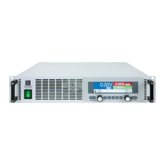
Page 22: Views
PS 9000 2U Series 1.8.4 Views Figure 1 - Front side Figure 2 - Rear side (standard version) EA Elektro-Automatik GmbH Fon: +49 2162 / 3785-0 www.elektroautomatik.de Page 22 Helmholtzstr. 31-33 • 41747 Viersen Fax: +49 2162 / 16230 ea1974@elektroautomatik.de... - Page 23 PS 9000 2U Series EA Elektro-Automatik GmbH Fon: +49 2162 / 3785-0 www.elektroautomatik.de Page 23 Helmholtzstr. 31-33 • 41747 Viersen Fax: +49 2162 / 16230 ea1974@elektroautomatik.de Germany...
- Page 24 PS 9000 2U Series Figure 5 - View from above, with DC cover (terminal type 1) EA Elektro-Automatik GmbH Fon: +49 2162 / 3785-0 www.elektroautomatik.de Page 24 Helmholtzstr. 31-33 • 41747 Viersen Fax: +49 2162 / 16230 ea1974@elektroautomatik.de Germany...
-
Page 25: Control Elements
“Off” indicate the state of the DC output, no matter if the device is manually controlled or remotely. LED “Power” Indicates different colours during the start of the device and once ready for operation, it turns green and remains for the period of operation. EA Elektro-Automatik GmbH Fon: +49 2162 / 3785-0 www.elektroautomatik.de Page 25 Helmholtzstr. -
Page 26: Construction And Function
1...3 1...3 Controller (DR) ≈ Commu- Panel nication (HMI) (KE) PS 9000 2U/3U Block diagram GPIB (opt.) EA Elektro-Automatik GmbH Fon: +49 2162 / 3785-0 www.elektroautomatik.de Page 26 Helmholtzstr. 31-33 • 41747 Viersen Fax: +49 2162 / 16230 ea1974@elektroautomatik.de Germany... -
Page 27: Scope Of Delivery
Replaces the standard Ethernet port by a permanently installed GPIB port. The device will keep the USB and analog interfaces. Via the GPIB port, it can only GPIB interface support SCPI commands. EA Elektro-Automatik GmbH Fon: +49 2162 / 3785-0 www.elektroautomatik.de Page 27 Helmholtzstr. -
Page 28: The Control Panel (Hmi)
Local The device has been locked by the user explicitly against remote control Alarm: Alarm condition which has not been acknowledged or still exists. EA Elektro-Automatik GmbH Fon: +49 2162 / 3785-0 www.elektroautomatik.de Page 28 Helmholtzstr. 31-33 • 41747 Viersen Fax: +49 2162 / 16230 ea1974@elektroautomatik.de... - Page 29 In manual operation every set value can be set in the increments given above. In this case the actual output values set by the device will lie within percentage tolerances as shown in the technical data sheets. These will influence the actual values. EA Elektro-Automatik GmbH Fon: +49 2162 / 3785-0 www.elektroautomatik.de Page 29 Helmholtzstr.
-
Page 30: Usb Port
The input voltage range of the set values and the output voltage range of the monitor val- ues, as well as reference voltage level can be switched in the settings menu of the device between 0-5 V and 0-10 V, in each case for 0-100%. EA Elektro-Automatik GmbH Fon: +49 2162 / 3785-0 www.elektroautomatik.de Page 30 Helmholtzstr. -
Page 31: Share Bus-Connection
The connection to a PC or other GPIB port is done with standard GPIB cables from stock, which can have straight or 90 ° connectors. When using cable with 90 ° connectors, the USB port will be inaccessible. EA Elektro-Automatik GmbH Fon: +49 2162 / 3785-0 www.elektroautomatik.de Page 31 Helmholtzstr. -
Page 32: Installation & Commissioning
(see „1.8.3. Specific technical data“) • Before connecting to the mains ensure that the connection is as shown on the product label. Overvoltage on the AC supply can cause equipment damage. EA Elektro-Automatik GmbH Fon: +49 2162 / 3785-0 www.elektroautomatik.de Page 32 Helmholtzstr. -
Page 33: Preparation
The handles on the front are for sliding in and out of the cabinet. Slots on the front plate are provided for fixing the device (fixing screws not included). Acceptable and inacceptable installation positions: Standing surface EA Elektro-Automatik GmbH Fon: +49 2162 / 3785-0 www.elektroautomatik.de Page 33 Helmholtzstr. -
Page 34: Connection To Ac Supply
M8 (8 mm) bolt on a brass block Screw clamp connection M6, on copper rail Recommendation: M8 ring lug with a 8.4 mm hole Recommendation: M6 ring lug with a 6.5 mm hole EA Elektro-Automatik GmbH Fon: +49 2162 / 3785-0 www.elektroautomatik.de Page 34 Helmholtzstr. -
Page 35: Grounding Of The Dc Output
• If grounding one of the DC output poles check if any pole of the load is already grounded. This could lead to a short circuit! EA Elektro-Automatik GmbH Fon: +49 2162 / 3785-0 www.elektroautomatik.de Page 35 Helmholtzstr. -
Page 36: Connection Of Remote Sensing
• The Share bus is referenced to DC minus. When building a series connection (where allowed, depending on model), the DC minus will shift its potential and so will the Share bus EA Elektro-Automatik GmbH Fon: +49 2162 / 3785-0 www.elektroautomatik.de... -
Page 37: Connecting The Analog Interface
In case of a firmware update, return of the equipment following repair or a location or configuration change, similar measures should be taken to those of initial start up. Refer to „2.3.11. Initial commission“. Only after successful checking of the device as listed may it be operated as usual. EA Elektro-Automatik GmbH Fon: +49 2162 / 3785-0 www.elektroautomatik.de Page 37 Helmholtzstr. -
Page 38: Initial Network Setup
Wait a few seconds before testing the new IP by entering it in the browser’s URL box. Opening the website again by using the host name is only possible after the device has restarted, because only then the new IP is reported to the DNS. EA Elektro-Automatik GmbH Fon: +49 2162 / 3785-0 www.elektroautomatik.de Page 38 Helmholtzstr. -
Page 39: Operation And Application
CC and this message will be passed as a signal to the analog interface, as well stored as status which can also be read as a status message via digital interface. EA Elektro-Automatik GmbH Fon: +49 2162 / 3785-0 www.elektroautomatik.de... -
Page 40: Power Regulation / Constant Power / Power Limiting
This situation of constant power can’t be indicated by status “CP”. Active derating can then only be detected by reading the actual values of voltage and current and by calculating the power. EA Elektro-Automatik GmbH Fon: +49 2162 / 3785-0 www.elektroautomatik.de... -
Page 41: Alarm Conditions
• the product of the output voltage and output current in the DC output reaches the adjusted OPP limit. This function serves to protect the connected load application so that this is not overloaded and possibly damaged due to an excessive power consumption. EA Elektro-Automatik GmbH Fon: +49 2162 / 3785-0 www.elektroautomatik.de Page 41 Helmholtzstr. -
Page 42: Manual Operation
The menu structure is shown schemati- cally on the next page. Some setting pa- rameters are self-explanatory, others are not. The latter will be explained on the pages following. EA Elektro-Automatik GmbH Fon: +49 2162 / 3785-0 www.elektroautomatik.de Page 42 Helmholtzstr. 31-33 • 41747 Viersen Fax: +49 2162 / 16230 ea1974@elektroautomatik.de... - Page 43 PS 9000 2U Series Underlined parameters show the default value after delivery or reset. EA Elektro-Automatik GmbH Fon: +49 2162 / 3785-0 www.elektroautomatik.de Page 43 Helmholtzstr. 31-33 • 41747 Viersen Fax: +49 2162 / 16230 ea1974@elektroautomatik.de Germany...
-
Page 44: Calibration Procedure
Here you can enter the date of the most recent calibration (year, month, day) Save and exit This menu item saves and leaves the setup menu to main display EA Elektro-Automatik GmbH Fon: +49 2162 / 3785-0 www.elektroautomatik.de Page 44 Helmholtzstr. - Page 45 Enable TCP Default setting: No keep-alive Activates/deactivates the so-called “keep-alive” functionality of Ethernet connections EA Elektro-Automatik GmbH Fon: +49 2162 / 3785-0 www.elektroautomatik.de Page 45 Helmholtzstr. 31-33 • 41747 Viersen Fax: +49 2162 / 16230 ea1974@elektroautomatik.de...
- Page 46 Default setting: off HMI Lock Activates the HMI lock. See „3.7. Control panel (HMI) lock“ for details Default settings: Lock all, No EA Elektro-Automatik GmbH Fon: +49 2162 / 3785-0 www.elektroautomatik.de Page 46 Helmholtzstr. 31-33 • 41747 Viersen Fax: +49 2162 / 16230 ea1974@elektroautomatik.de...
-
Page 47: Adjustment Limits
I-max to 100 A while the currently adjusted current set value is 120 A, then the set value first would have to be reduced to 100 A or less. The same applies vice versa when adjusting I-min. EA Elektro-Automatik GmbH Fon: +49 2162 / 3785-0 www.elektroautomatik.de Page 47 Helmholtzstr. -
Page 48: Manual Adjustment Of Set Values
• The actual regulation mode is displayed no matter what pair of physical values is currently shown, as the example in the upper figure on the right side depicts with CV EA Elektro-Automatik GmbH Fon: +49 2162 / 3785-0 www.elektroautomatik.de Page 48 Helmholtzstr. -
Page 49: The Quick Menu
See the external documentation “Programming Guide ModBus & SCPI” if you are using custom software, or refer to the external documentation of LabView VIs or other software provided by the manufacturer. EA Elektro-Automatik GmbH Fon: +49 2162 / 3785-0 www.elektroautomatik.de Page 49 Helmholtzstr. -
Page 50: Remote Control
Programming details for the interfaces, the communication protocols etc. are to be found in the documentation “Programming Guide ModBus & SCPI“ which is supplied on the included USB stick or which is available as down- load from the manufacturer’s website. EA Elektro-Automatik GmbH Fon: +49 2162 / 3785-0 www.elektroautomatik.de Page 50 Helmholtzstr. -
Page 51: Remote Control Via The Analog Interface (Ai)
„3.6.2. Device alarm handling“. Acknowledgement is done with pin REM-SB switching the DC output off and on again, means a HIGH-LOW-HIGH edge (min. 50ms for LOW) when using the default level setting for this pin. EA Elektro-Automatik GmbH Fon: +49 2162 / 3785-0 www.elektroautomatik.de... - Page 52 *** Mains blackout, mains undervoltage or PFC error **** Only during remote control ***** The error of a set value input adds to the general error of the related value on the DC output of the device EA Elektro-Automatik GmbH Fon: +49 2162 / 3785-0 www.elektroautomatik.de Page 52 Helmholtzstr.
- Page 53 If the pin is unconnected or the connected contact is open, the pin will be HIGH. With parameter “Analog interface REM-SB” being set to “normal”, it requests “DC output on”. So when activating remote control, the DC output will instantly switch on. EA Elektro-Automatik GmbH Fon: +49 2162 / 3785-0 www.elektroautomatik.de Page 53 Helmholtzstr.
- Page 54 Reading actual values Via the AI the output values for current and voltage can be monitored. These can be read using a standard multimeter or similar. EA Elektro-Automatik GmbH Fon: +49 2162 / 3785-0 www.elektroautomatik.de Page 54 Helmholtzstr. 31-33 • 41747 Viersen Fax: +49 2162 / 16230 ea1974@elektroautomatik.de...
-
Page 55: Alarms And Monitoring
Triggers an alarm if the internal temperature reaches a certain limit. The Display, analog perature DC output will be switched off. IF, digital IF EA Elektro-Automatik GmbH Fon: +49 2162 / 3785-0 www.elektroautomatik.de Page 55 Helmholtzstr. 31-33 • 41747 Viersen Fax: +49 2162 / 16230 ea1974@elektroautomatik.de... -
Page 56: Control Panel (Hmi) Lock
This request pop-up will appear: Unlock the HMI by pushing within 5 seconds, otherwise the pop-up will disappear and the HMI re- mains locked. EA Elektro-Automatik GmbH Fon: +49 2162 / 3785-0 www.elektroautomatik.de Page 56 Helmholtzstr. 31-33 • 41747 Viersen Fax: +49 2162 / 16230 ea1974@elektroautomatik.de... -
Page 57: Loading And Saving A User Profile
In the screen you can now select “View Profile n” in order to check the stored settings and to decide, whether this profile is going to be loaded or not. Navigate to “Load Profile n” and confirm with to finally load the profile into the work profile. EA Elektro-Automatik GmbH Fon: +49 2162 / 3785-0 www.elektroautomatik.de Page 57 Helmholtzstr. -
Page 58: Other Applications
They can, if needed, be monitored by reading actual values and status. The master unit is not restricted and can be used like a stand-alone unit. EA Elektro-Automatik GmbH Fon: +49 2162 / 3785-0 www.elektroautomatik.de Page 58 Helmholtzstr. -
Page 59: Series Connection
It is thus recommended to leave the DC output switched off as long as the battery is not supposed to be charged. EA Elektro-Automatik GmbH Fon: +49 2162 / 3785-0 www.elektroautomatik.de... -
Page 60: Two Quadrants Operation (2Qo)
One PSU, preferably PSU 1, has to be set to Master for the E.U.T Share bus connection. EA Elektro-Automatik GmbH Fon: +49 2162 / 3785-0 www.elektroautomatik.de Page 60 Helmholtzstr. 31-33 • 41747 Viersen Fax: +49 2162 / 16230 ea1974@elektroautomatik.de... - Page 61 When reaching 27 V, the power supply will deliver only the current needed to maintain the battery voltage. EA Elektro-Automatik GmbH Fon: +49 2162 / 3785-0 www.elektroautomatik.de...
- Page 62 • Newly implemented features may require an updated documentation (user manual and/or programming guide, as well as LabView VIs), which is often delivered only later, sometimes significantly later EA Elektro-Automatik GmbH Fon: +49 2162 / 3785-0 www.elektroautomatik.de Page 62 Helmholtzstr.
- Page 63 The calibration procedure, as explained below, is an example with model PS 9080-120 2U. Other models are treated the same way, with values according to the particular PS model and the required load. EA Elektro-Automatik GmbH Fon: +49 2162 / 3785-0 www.elektroautomatik.de...
- Page 64 Assure yourself the value is correct and submit with Repeat point 5. for the next three steps (total of four steps). EA Elektro-Automatik GmbH Fon: +49 2162 / 3785-0 www.elektroautomatik.de Page 64 Helmholtzstr.
- Page 65 Questions or problems with operation of the device, use of optional components, with the documentation or soft- ware, can be addressed to technical support either by telephone or e-Mail. Address e-Mail Telephone EA Elektro-Automatik GmbH Technical support: Switchboard: +49 2162 / 37850 Helmholtzstr. 31-37 support@elektroautomatik.de...
- Page 66 EA Elektro-Automatik GmbH & Co. KG Development - Production - Sales Helmholtzstraße 31-37 41747 Viersen Germany Fon: 02162 / 37 85-0 ea1974@elektroautomatik.de www.elektroautomatik.de...
Need help?
Do you have a question about the PS 9040-40 2U and is the answer not in the manual?
Questions and answers