Sign In
Upload
Manuals
Brands
Elektro-Automatik Manuals
Power Supply
PS 9000 T Series
Elektro-Automatik PS 9000 T Series Manuals
Manuals and User Guides for Elektro-Automatik PS 9000 T Series. We have
2
Elektro-Automatik PS 9000 T Series manuals available for free PDF download: Operating Manual
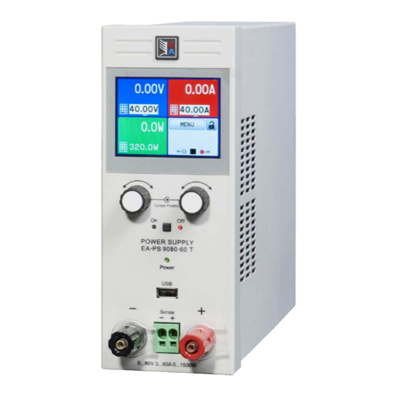
Elektro-Automatik PS 9000 T Series Operating Manual (130 pages)
DC Laboratory Power Supply
Brand:
Elektro-Automatik
| Category:
Power Supply
| Size: 2 MB
Table of Contents
Deutsch
3
Table of Contents
3
Zu diesem Dokument
4
Aufbewahrung und Verwendung
4
Urheberschutz (Copyright)
4
Geltungsbereich
4
Symbolerläuterungen
4
Gewährleistung und Garantie
4
Haftungsbeschränkungen
4
Entsorgung des Gerätes
5
Produktschlüssel
5
Bestimmungsgemäße Verwendung
5
Sicherheit
6
Sicherheitshinweise
6
Verantwortung des Bedieners
7
Pflichten des Betreibers
7
Anforderungen an das Bedienpersonal
7
Alarmsignale
8
Technische Daten
8
Zulässige Betriebsbedingungen
8
Allgemeine Technische Daten
8
Spezifische Technische Daten
9
Ansichten
19
Aufbau und Funktion
23
Allgemeine Beschreibung
23
Blockdiagramm
23
Lieferumfang
24
Optionales Zubehör
24
Die Bedieneinheit (HMI)
25
USB-Port (Rückseite)
27
Sense-Anschluß (Fernfühlung)
27
Ethernetport
28
Analogschnittstelle
28
Installation & Inbetriebnahme
29
Lagerung
29
Verpackung
29
Auspacken und Sichtkontrolle
29
Installation
29
Sicherheitsmaßnahmen vor Installation und Gebrauch
29
Vorbereitung
29
Aufstellung des Gerätes
29
Anschließen von DC-Lasten
31
Erdung des DC-Ausgangs
31
Anschließen der Fernfühlung
32
Anschließen der Analogen Schnittstelle
32
Anschließen des USB-Ports (Rückseite)
32
Erstinbetriebnahme
33
Erneute Inbetriebnahme nach Firmwareupdates Bzw. Längerer Nichtbenutzung
33
Bedienung und Verwendung
34
Personenschutz
34
Regelungsarten
34
Spannungsregelung / Konstantspannung
34
Leistungsregelung / Konstantleistung / Leistungsbegrenzung
35
Stromregelung / Konstantstrom / Strombegrenzung
35
Alarmzustände
36
Power Fail
36
Überleistung (Overpower)
36
Überspannung (Overvoltage)
36
Überstrom (Overcurrent)
36
Übertemperatur (Overtemperature)
36
Ausschalten des Gerätes
37
Einschalten des Gerätes
37
Konfiguration IM Menu
37
Manuelle Bedienung
37
Einstellgrenzen (Limits)
45
Sollwerte Manuell Einstellen
45
Ansichtsmodus der Hauptanzeige Wechseln
47
DC-Ausgang Ein- oder Ausschalten
47
Datenaufzeichnung (USB-Logging)
48
Allgemeines
49
Bedienorte
49
Fernsteuerung
49
Fernsteuerung über eine Digitale Schnittstelle
49
Fernsteuerung über Analogschnittstelle (AS)
50
Alarme und Überwachung
54
Gerätealarme Handhaben
54
Bedieneinheit (HMI) Sperren
55
Einstellgrenzen (Limits) Sperren
55
Nutzerprofile Laden Und Speichern
56
Betrieb als Batterielader
58
Instandhaltung & Wartung
59
Parallelschaltung
58
Reihenschaltung
58
Weitere Anwendungen
58
Aktualisierung der Firmwares
59
Defekte Netzsicherung Tauschen
59
Fehlersuche / Fehlerdiagnose / Reparatur
59
Wartung / Reinigung
59
Abgleichvorgang
60
Einleitung
60
Nachjustierung (Kalibrierung)
60
Vorbereitung
60
Ersatzableitstrommessung nach DIN VDE 0701-1
62
Service & Support
63
Kontaktmöglichkeiten
63
Reparaturen
63
English
69
About this Document
70
Copyright
70
Limitation of Liability
70
Retention and Use
70
Symbols and Warnings
70
Validity
70
Warranty
70
Disposal of Equipment
71
Intended Usage
71
Product Key
71
Responsibility of the User
72
Safety
72
Safety Notices
72
Responsibility of the Operator
73
User Requirements
73
Alarm Signals
74
Approved Operating Conditions
74
General Technical Data
74
Technical Data
74
Specific Technical Data
75
Views
85
Block Diagram
89
Construction and Function
89
General Description
89
Optional Accessories
90
Scope of Delivery
90
The Control Panel (HMI)
91
Sense" Connector (Remote Sensing)
93
USB Port (Back Side)
93
Analog Interface
94
Ethernet Port
94
Installation
95
Installation & Commissioning
95
Installing the Device
95
Packaging
95
Preparation
95
Safety Procedures before Installation and Use
95
Storage
95
Unpacking and Visual Check
95
Connection to DC Loads
97
Grounding of the DC Output
97
Connecting the Analog Interface
98
Connecting the USB Port (Rear Side)
98
Connection of Remote Sensing
98
Commission after a Firmware Update or a Long Period of Non-Use
99
Operation and Application
100
Initial Commission
99
Operating Modes
100
Personal Safety
100
Voltage Regulation / Constant Voltage
100
Current Regulation / Constant Current / Current Limiting
101
Power Regulation / Constant Power / Power Limiting
101
Alarm Conditions
102
Overcurrent Protection
102
Overpower Protection
102
Overtemperature
102
Overvoltage Protection
102
Power Fail
102
Configuration Via Menu
103
Manual Operation
103
Switching off the Device
103
Switching on the Device
103
Adjustment Limits (Limits)
111
Manual Adjustment of Set Values
111
Switching the DC Output on or off
113
Switching the Main Screen View
113
Recording to USB Stick (Logging)
114
Control Locations
115
General
115
Remote Control
115
Remote Control Via a Digital Interface
115
Remote Control Via the Analog Interface (AI)
116
Alarms and Monitoring
120
Device Alarm Handling
120
Control Panel (HMI) Lock
121
Limits Lock
121
Loading And Saving A User Profile
122
Operation as Battery Charger
123
Service and Maintenance
124
Other Applications
123
Parallel Operation
123
Series Connection
123
Fault Finding / Diagnosis / Repair
124
Firmware Updates
124
Maintenance / Cleaning
124
Replacing a Defect Mains Fuse
124
Calibration
125
Calibration Procedure
125
Contact and Support
127
Preface
125
Preparation
125
Contact Options
127
Repairs
127
Advertisement
Elektro-Automatik PS 9000 T Series Operating Manual (64 pages)
DC Laboratory Power Supply
Brand:
Elektro-Automatik
| Category:
Power Supply
| Size: 1 MB
Table of Contents
Table of Contents
3
About this Document
4
Retention and Use
4
Copyright
4
Validity
4
Symbols and Warnings
4
Warranty
4
Limitation of Liability
4
Disposal of Equipment
5
Product Key
5
Intended Usage
5
Safety
6
Safety Notices
6
Responsibility of the User
6
Responsibility of the Operator
7
User Requirements
7
Alarm Signals
8
Technical Data
8
Approved Operating Conditions
8
General Technical Data
8
Specific Technical Data
9
Views
19
Construction and Function
23
General Description
23
Block Diagram
23
Scope of Delivery
24
Optional Accessories
24
The Control Panel (HMI)
25
USB Port (Back Side)
27
Sense" Connector (Remote Sensing)
27
Ethernet Port
28
Analog Interface
28
Installation & Commissioning
29
Storage
29
Packaging
29
Unpacking and Visual Check
29
Installation
29
Safety Procedures before Installation and Use
29
Preparation
29
Installing the Device
29
Connection to DC Loads
31
Grounding of the DC Output
31
Connection of Remote Sensing
32
Connecting the Analog Interface
32
Connecting the USB Port (Rear Side)
32
Initial Commission
33
Commission after a Firmware Update or a Long Period of Non-Use
33
Operation and Application
34
Operating Modes
34
Personal Safety
34
Voltage Regulation / Constant Voltage
34
Current Regulation / Constant Current / Current Limiting
35
Power Regulation / Constant Power / Power Limiting
35
Alarm Conditions
36
Overcurrent Protection
36
Overpower Protection
36
Overtemperature
36
Overvoltage Protection
36
Power Fail
36
Configuration Via Menu
37
Manual Operation
37
Switching off the Device
37
Switching on the Device
37
Adjustment Limits (Limits)
45
Manual Adjustment of Set Values
45
Switching the DC Output on or off
47
Switching the Main Screen View
47
Recording to USB Stick (Logging)
48
Control Locations
49
General
49
Remote Control
49
Remote Control Via a Digital Interface
49
Remote Control Via the Analog Interface (AI)
50
Alarms and Monitoring
54
Device Alarm Handling
54
Control Panel (HMI) Lock
55
Limits Lock
55
Loading And Saving A User Profile
56
Operation as Battery Charger
57
Service and Maintenance
58
Other Applications
57
Parallel Operation
57
Series Connection
57
Fault Finding / Diagnosis / Repair
58
Firmware Updates
58
Maintenance / Cleaning
58
Replacing a Defect Mains Fuse
58
Calibration
59
Calibration Procedure
59
Contact and Support
61
Preface
59
Preparation
59
Contact Options
61
Repairs
61
Advertisement
Related Products
Elektro-Automatik PS 9000 3U
Elektro-Automatik PS 9000 2U Series
Elektro-Automatik PS 9000 1U
Elektro-Automatik PS 9080-50
Elektro-Automatik PS 9080-100
Elektro-Automatik PS 9040-60 2U
Elektro-Automatik PS 9080-60 2U
Elektro-Automatik PS 9040-120 2U
Elektro-Automatik PS 9040-20 T
Elektro-Automatik PS 9040-40 T
Elektro-Automatik Categories
Power Supply
UPS
Enclosure
Test Equipment
Portable Generator
More Elektro-Automatik Manuals
Login
Sign In
OR
Sign in with Facebook
Sign in with Google
Upload manual
Upload from disk
Upload from URL