Table of Contents
Advertisement
Quick Links
Advertisement
Table of Contents

Related Manuals for Elektro-Automatik PS 9000 1U


Summary of Contents for Elektro-Automatik PS 9000 1U
- Page 1 Operating Guide PS 9000 1U DC Laboratory Power Supply Attention! This document is only valid for devices with firmware “KE: 3.07” and “HMI: 2.05”, or Doc ID: PS91UEN higher. For availability of up- dates for your device check our Revision: 07 website or contact us.
-
Page 3: Table Of Contents
PS 9000 1U Series TABLE OF CONTENTS GENERAL About this document ........5 2.3.10 Connecting the USB port ......26 1.1.1 Retention and use ..........5 2.3.11 Initial commission .........26 1.1.2 Copyright ............5 2.3.12 Initial network setup ........27 1.1.3 Validity ............5 2.3.13 Commission after a firmware update or a long period of non-use .........27... - Page 4 PS 9000 1U Series SERVICE & MAINTENANCE Maintenance / cleaning ........50 Fault finding / diagnosis / repair....50 4.2.1 Firmware update ..........50 Calibration (readjustment) ......51 4.3.1 Preface ............51 4.3.2 Preparation ...........51 4.3.3 Calibration procedure ........51 CONTACT AND SUPPORT General ............53 Contact options ..........53...
-
Page 5: General
EA Elektro-Automatik guarantees the functional competence of the applied technology and the stated performance parameters. The warranty period begins with the delivery of free from defects equipment. Terms of guarantee are included in the general terms and conditions (TOS) of EA Elektro-Automatik. Limitation of liability All statements and instructions in this manual are based on current norms and regulations, up-to-date technology and our long term knowledge and experience. -
Page 6: Disposal Of Equipment
PS 9000 1U Series Disposal of equipment A piece of equipment which is intended for disposal must, according to European laws and regulations (ElektroG, WEEE) be returned to the manufacturer for scrapping, unless the person operating the piece of equipment or an- other, delegated person is conducting the disposal. -
Page 7: Safety
PS 9000 1U Series Safety 1.7.1 Safety notices Mortal danger - Hazardous voltage • Electrical equipment operation means that some parts can be under dangerous voltage. Therefore all parts under voltage must be covered! • All work on connections must be carried out under zero voltage (output not connected to load) and may only be performed by qualified and informed persons. -
Page 8: Responsibility Of The User
PS 9000 1U Series 1.7.2 Responsibility of the user The equipment is in industrial operation. Therefore the operators are governed by the legal safety regulations. Alongside the warning and safety notices in this manual the relevant safety, accident prevention and environmental regulations must also be applied. -
Page 9: Alarm Signals
PS 9000 1U Series 1.7.5 Alarm signals The equipment offers various possibilities for signalling alarm conditions, however, not for danger situations. The signals may be optical (on the display as text) acoustic (piezo buzzer) or electronic (pin/status output of an analog interface). -
Page 10: Specific Technical Data
PS 9000 1U Series 1.8.3 Specific technical data Model 1U 1500 W PS 9080-50 PS 9200-25 PS 9360-15 PS 9500-10 PS 9750-06 AC Input Without derating: 150...264 V AC, 50/60 Hz Input voltage / frequency With derating to 1000 W: 100...150 V AC... - Page 11 PS 9000 1U Series Model 1U 1500 W PS 9080-50 PS 9200-25 PS 9360-15 PS 9500-10 PS 9750-06 Analog interface Type Sub-D, 15 pole, female Set value inputs U, I, P Actual value output U, I Control signals DC output on/off, remote control on/off...
- Page 12 PS 9000 1U Series Model 1U 3000 W PS 9080-100 PS 9200-50 PS 9360-30 PS 9500-20 PS 9750-12 AC Input Without derating: 207...264 V AC, 45...66 Hz Input voltage / frequency With derating to 2500 W: 180...207 V AC Input connection...
- Page 13 PS 9000 1U Series Model 1U 3000 W PS 9080-100 PS 9200-50 PS 9360-30 PS 9500-20 PS 9750-12 Analog interface Type Sub-D, 15 pole, female Set value inputs U, I, P Actual value output U, I Control signals DC output on/off, remote control on/off...
-
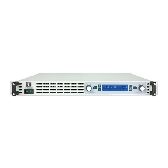
Page 14: Views
PS 9000 1U Series 1.8.4 Views EA Elektro-Automatik GmbH Fon: +49 2162 / 3785-0 www.elektroautomatik.de Page 14 Helmholtzstr. 31-37 • 41747 Viersen Fax: +49 2162 / 16230 ea1974@elektroautomatik.de Germany... - Page 15 PS 9000 1U Series EA Elektro-Automatik GmbH Fon: +49 2162 / 3785-0 www.elektroautomatik.de Page 15 Helmholtzstr. 31-37 • 41747 Viersen Fax: +49 2162 / 16230 ea1974@elektroautomatik.de Germany...
- Page 16 PS 9000 1U Series Figure 5 - Top view EA Elektro-Automatik GmbH Fon: +49 2162 / 3785-0 www.elektroautomatik.de Page 16 Helmholtzstr. 31-37 • 41747 Viersen Fax: +49 2162 / 16230 ea1974@elektroautomatik.de Germany...
-
Page 17: Control Elements
PS 9000 1U Series 1.8.5 Control elements Figure 6- Control Panel Overview of the elements of the control panel For a detailed description see section „1.9.4. The control panel (HMI)“. Display Used for indication of set values, menus, conditions, actual values and status. -
Page 18: Construction And Function
General description The electronic high performance power supplies of the PS 9000 1U series are especially suitable for test systems and industrial controls due to their compact construction in a 19” enclosure with 1 height unit (1U = 44,45 mm = 1.75”). -
Page 19: The Control Panel (Hmi)
PS 9000 1U Series 1.9.4 The control panel (HMI) The HMI (Human Machine Interface) consists of a display, two rotary knobs with pushbutton function and six pushbuttons. 1.9.4.1 Display The graphic display is divided into a number of areas. In normal operation the left upper half is used to show actual... -
Page 20: Share Bus-Connection
PS 9000 1U Series This area furthermore displays various status texts: Display Description Locked The HMI is locked Remote The device is under remote control from... Analog ...the built-in analog interface ...the built-in USB port or a plug in interface module Ethernet ...the built-in Ethernet/LAN port... -
Page 21: Usb Port
PS 9000 1U Series 1.9.6 USB port The USB-B port on the back side of the device is provided for communication with the device and for firmware updates. The included USB cable can be used to connect the device to a PC (USB 2.0, USB 3.0). The driver is delivered on the included USB stick or is available as download and installs a virtual COM port. -
Page 22: Installation & Commissioning
Preparation Mains connection for a PS 9000 1U series device is done via the included 2 meters long 3 pole mains cord. In case a different AC wiring is required, make sure that the other cable has a minimum cross section of 1.5 mm² (AWG 12). -
Page 23: Installing The Device
PS 9000 1U Series 2.3.3 Installing the device • Select the location for the device so that the connection to the load is as short as possible! • Leave sufficient space behind the equipment, minimum 30 cm (12”), for ventilation! • The device isn’t stackable! -
Page 24: Connection To Dc Loads
PS 9000 1U Series 2.3.5 Connection to DC loads In the case of a device with a high nominal current and hence a thick and heavy DC connection cable it is necessary to take account of the weight of the cable and the strain imposed on the DC connection. -
Page 25: Grounding Of The Dc Output
PS 9000 1U Series 2.3.6 Grounding of the DC output Grounding one of the DC output poles is allowed. Doing so can result in a potential shift of the grounded pole against PE. Because of insulation, there is a max. allowed potential shift of the DC output poles, which also depends on the device model. -
Page 26: Connecting The "Share" Bus
PS 9000 1U Series 2.3.8 Connecting the “Share” bus The “Share” connector on the back side is intended to balance the current of multiple units in parallel operation, especially when using the integrated function generator of the master unit. For further information about this mode of operation can be found in section „3.9.1. -
Page 27: Initial Network Setup
PS 9000 1U Series 2.3.12 Initial network setup The device is delivered with default network parameters (see „3.4.3.6. Menu “Communication”“). The Ethernet/ LAN port is immediately ready for use after the initial commission. Default parameters: IP: 192.168.0.2 Subnet mask: 255.255.255.0 Gateway: 192.168.0.1... -
Page 28: Operation And Application
PS 9000 1U Series Operation and application Important notes 3.1.1 Personal safety • In order to guarantee safety when using the device, it is essential that only persons operate the device who are fully acquainted and trained in the required safety measures to be taken when working with dangerous electrical voltages • For models which can generate a voltage which is dangerous by contact, or is connected to... -
Page 29: Current Regulation / Constant Current / Current Limiting
3.2.3.1 Power derating The power supplies of series PS 9000 1U offer an extended AC supply voltage range, but are dedicated for the use at typical 230 V , ±10%. Below a certain supply voltage, all models will automatically start to derate, i.e. re- duce the maximum available output power. -
Page 30: Alarm Conditions
PS 9000 1U Series Alarm conditions This section only gives an overview about device alarms. What to do in case your device indi- cates an alarm condition is described in section „3.6. Alarms and monitoring“. As a basic principle, all alarm conditions are signaled optically (Text + message in the display), acoustically (if activated) and as a readable status via the digital interface. -
Page 31: Manual Operation
PS 9000 1U Series Manual operation 3.4.1 Switching on the device The device should, as far as possible, always be switched on using the rotary switch on the front of the device. Alternatively this can take place using an external cutout (contactor, circuit breaker) of suitable current capacity. - Page 32 PS 9000 1U Series 3.4.3.1 Menu “General Settings” Element Description Allow remote control Selection No means that the device can’t be remotely controlled over any of the digital or analog interfaces. If remote control isn’t allowed, the status will be shown as Local in the status area on the main display.
- Page 33 PS 9000 1U Series 3.4.3.2 Menu “Calibrate Device” From within this menu, a calibration and readjustment procedure for output voltage and current, separate proce- dures for set value and actual value, can be started. For further details refer to „4.3. Calibration (readjustment)“.
- Page 34 PS 9000 1U Series Sub menu “IP Settings 2” Element Description Port Default value: 5025 Adjust the socket port here, which belongs to the IP address and serves for TCP/P access when controlling the device remotely via Ethernet DNS address Default value: 0.0.0.0...
-
Page 35: Adjustment Limits
PS 9000 1U Series 3.4.4 Adjustment limits By default, all set values (U, I, P) are freely adjustable from 0 to 102% of the rated value. This may be obstructive in some cases, especially for protection of applications against overcurrent. Therefore upper and lower limits for current and voltage can be set which limit the range of the adjustable set values. -
Page 36: Display Modes For Actual And Set Values
Display modes for actual and set values In general, the display of a PS 9000 1U device shows the actual output voltage and the related set value in the left half of the display and the actual output current and related set value in the right half. In order to have the power set value in direct access, the display mode can be switched. -
Page 37: The Quick Menu
PS 9000 1U Series 3.4.7 The quick menu The quick menu is an alternative menu for quick access to offline features while the DC output is online. It is accessible with the button and looks like this: Navigation in the menu is also done with arrow buttons You can select the between view mode and the HMI lock, each with three button pushes. -
Page 38: Remote Control
PS 9000 1U Series Remote control 3.5.1 General Remote control is principally possible via any of the built-in interface ports USB, Ethernet/LAN or analog. Important here is that only the analog or any digital interface can be in control. It means that if, for example, an attempt were to be made to switch to remote control via the digital interface whilst analog remote control is active (pin REMOTE = LOW) the device would report an error at the digital interface. -
Page 39: Remote Control Via The Analog Interface (Ai)
PS 9000 1U Series 3.5.4 Remote control via the analog interface (AI) 3.5.4.1 General The built-in, galvanically isolated, 15-pole analog interface (short: AI) is located on the rear side of the device and offers the following functions: • Remote control of current, voltage and power • Remote status monitoring (CV, DC output status) - Page 40 PS 9000 1U Series 3.5.4.4 Analog interface specification Pin Name Type* Description Default levels Electrical specification 0…10 V or. 0...5 V corre- VSEL Set voltage value Accuracy 0-5 V range: < 0.4% ***** spond to 0..100% of U Accuracy 0-10 V range: < 0.2% ***** 0…10 V or.
- Page 41 PS 9000 1U Series 3.5.4.6 Simplified diagram of the pins Digital Input (DI) Analog Input (AI) The DI is internally pulled up and thus it re- High resistance input (impedance V~0.5 quires to use a contact with low resistance >40 k..100 kΩ) of an operational (relay, switch, contactor etc.) in order to...
- Page 42 PS 9000 1U Series In case the DC output is already switched on, toggling the pin will switch the DC output off, similar to what it does in analog remote control: Parameter Level on pin „Analog Behavior output REM-SB interface REM-SB“...
-
Page 43: Alarms And Monitoring
PS 9000 1U Series Alarms and monitoring 3.6.1 Definition of terms Device alarms (see „3.3. Alarm conditions“) are defined as conditions like overvoltage or overtemperature, signaled in any form to the user of the device in order to take notice. -
Page 44: Control Panel (Hmi) Lock
PS 9000 1U Series ► How to configure the device alarms OVP, OCP and OPP Switch off the DC output and push button to call the setup menu. In the menu navigate to Settings and push . Then in the sub menu navigate to Protection and push again. -
Page 45: Loading And Saving An User Profile
PS 9000 1U Series Loading and saving an user profile The menu “Profiles” serves to select between a default profile and up to 5 user profiles. A profile is a collection of all settings and set values. Upon delivery, or after a reset, all 6 profiles have the same settings and all set values are 0. -
Page 46: Other Applications
PS 9000 1U Series Other applications 3.9.1 Parallel operation in Share Bus mode Multiple devices of same kind and model can be connected in parallel in order to create a system with higher total current and hence higher power. To achieve that, the units have to be connected with their DC outputs and their Share Bus. -
Page 47: Series Connection
PS 9000 1U Series 3.9.1.5 Alarms and other problem situations Parallel operation, due to the connection of multiple units and their interaction, can cause additional problem sit- uations which do not occur when operating individual units. For such occurrences the following regulations have been defined: • If one or more slave units are switched off on the AC side (power switch, supply undervoltage) and come back... -
Page 48: Two Quadrants Operation (2Qo)
This mode of operation refers to the use of a source, in this case a power supply of series PS 9000 1U, and a sink, in this case an electronic load of a compat- ible series (see „1.9.5. Share Bus-Connection“). The source and the sink work alternatively in order to test a device such as a battery, by deliberately charging and discharging it as part of a functional or final test. - Page 49 PS 9000 1U Series 3.9.4.3 Settings on the devices The master-slave settings in the MENU of the load device(s) also affect the Share bus. For correct 2QO operation, all involved load units must be slaves on the Share bus. This is achieved by setting the master-slave mode to OFF or SLAVE, depending on if there is digital master-slave in use or not.
- Page 50 PS 9000 1U Series Service & maintenance Maintenance / cleaning The device needs no maintenance. Cleaning may be needed for the internal fans, the frequency of cleanse is depending on the ambient conditions. The fans serve to cool the components which are heated by the inherent power loss.
- Page 51 4.3.1 Preface The devices of series PS 9000 1U feature a function to readjust the most important output values when doing a calibration and in case these values have moved out of tolerance. The readjustment is limited to compensate small differences of up to 1% or 2% of the max. value. There are several reasons which could make it necessary...
- Page 52 PS 9000 1U Series 4.3.3.1 Calibrating the set values ► How to calibrate the DC output voltage Connect a multimeter to the DC output. Connect a load and set it to approx. 5% of the nominal current of the power supply as load current, in this example let’s use 4 A.
- Page 53 PS 9000 1U Series 4.3.3.3 Calibrating the actual values Actual values of output voltage (with and without remote sensing) and output current are calibrated almost the same way as the set values, but here you don’t need to enter anything, just confirm the displayed values. Please proceed the above steps and instead of Output value select Actual value in the sub menus.
- Page 54 EA Elektro-Automatik GmbH & Co. KG Development - Production - Sales Helmholtzstraße 31-37 41747 Viersen Germany Fon: +49 2162 / 37 85-0 Fax: +49 2162 / 16 230 Mail: ea1974@elektroautomatik.de Web: www.elektroautomatik.de...
Need help?
Do you have a question about the PS 9000 1U and is the answer not in the manual?
Questions and answers