Table of Contents
Advertisement
Quick Links
Advertisement
Chapters
Table of Contents

Related Manuals for Elektro-Automatik PS 8000 T Series


Summary of Contents for Elektro-Automatik PS 8000 T Series
- Page 1 实验室电源供应器系列 Laboratory Power Supply Series PS 8000 T PS 8016-20T: 09 200 120 PS 8160-04T: 09 200 125 PS 8032-10T: 09 200 121 PS 8080-40T: 09 200 126 PS 8065-05T: 09 200 122 PS 8080-60T: 09 200 127 PS 8032-30T: 09 200 123 PS 8360-10T: 09 200 128...
- Page 2 地址:苏州吴中区珠江南路378号431室 邮箱:amaygang@163.com 网址:www.d-wellmeter.com 传真:0512-66315383 电话:0512-66315386 手机:13913158248 免费服务热线:400-902-3318...
- Page 3 一般信息 关于 安全说明 Elektro-Automatik GmbH & Co. KG Helmholtzstrasse 31-33 危险电压 41747 Viersen 警告:本产品输出电压可能上升至危险级别(> 60 VDC)! Germany 产品上所有带电元件必须有外遮盖。输出端的所有操作必须在 电话: +49 2162 / 37850 产品与主电源(电源开关关闭)断开时才能执行,且可只有受 传真: +49 2162 / 16230 训过电流危险知识的专业人员执行此类操作。负载与本产品间 的任何连接必须有防碰擦装置。连到功率输出端的应用设备必 网址: www.elektroautomatik.cn 须配置好,并且有保险丝熔断保护,这样可防止使用过程中由 邮箱: ea1974@elektroautomatik.cn 于过载或误操作损坏产品或更严重事情发生。 © Elektro-Automatik 严禁翻版、复制或部分错误地使用该说明书,否则将承担相应...
-
Page 4: Table Of Contents
10.3 模拟接口各引脚分布 ..................16 11. 其它 ...................... 17 11.1 其它附件和选项功能 ..................17 11.2 并联 ....................17 11.3 串联 ....................17 11.4 固件更新 ....................17 © 2006, Elektro-Automatik GmbH & Co. KG Irrtümer und Änderungen vorbehalten PS 8000 T 系列 日期: 20.04.2011 产品说明书... -
Page 5: 技术规格
关于产品 1. 介绍 2. 技术规格 PS 8000T系列是结构紧凑、坚固耐用的实验室电源,在如此小 控制面板和显示器 体积下却具备多项有趣特征。 除电源产品的标准功能外,用户还可定义和恢复5组不同的预 设值,或使用可在0...5V或0...10V普通电压范围内工作的内置 型号 模拟接口。 LED式7段显示器,4位数,加逗号 显示器: 还提供一种简易的监控本产品或完全程控制方法。还可选择数 2个旋转编码器,6个按钮 旋钮: 字接口卡,通过电脑实现更宽光谱范围的控制和监控功能。 通过接口卡的使用可轻易地将产品整合于现有系统内,且根本 显示格式 不需配置接口卡或仅需配置少数设定值。 额定值限定最大可调范围。 本产品通过接口卡可连接其他类型电源,并借此控制它们。或 者通过外置控制系统,如PLC-可编程控制器,对本产品进行 电压和电流实际值和设定值同时显示,过压门限设定值则分开 控制和监测。 显示。 本产品由微处理器控制,得以使之能准确、快速地测量并显示 各实际值。 电压的显示 塔式结构的设计实现了节省空间的同时,又能适合复杂和高性 4位数 分辨率: 能的应用。例如:应用于研发或教育领域,具有可变功率以进 0.00V...99.99V 格式: 行不同演示或测试的工业化测试设备。 0.0V…999.9V 主功能一览: •... -
Page 6: 各型号详细规格
关于产品 各型号详细规格 © 2006, Elektro-Automatik GmbH & Co. KG Irrtümer und Änderungen vorbehalten PS 8000 T 系列 日期: 20.04.2011 产品说明书... -
Page 7: 产品描述
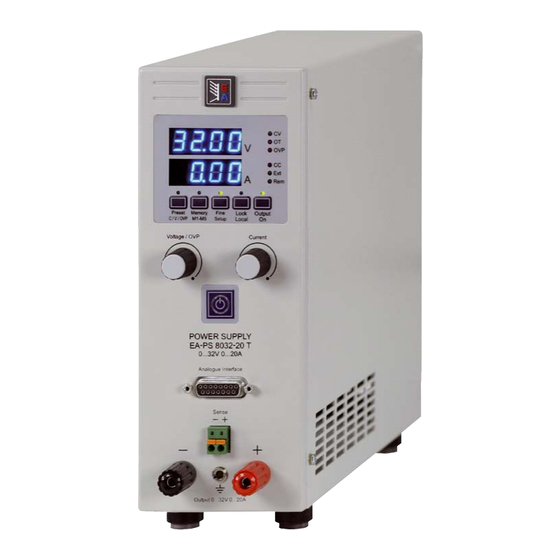
关于产品 3. 产品描述 前视图 关于旋钮、按钮和端子的描述: 1) 功率输出安全插座,带极性 用于配4mm的Bueschel插头或铲型接线夹片。 2) 程感测输入插座,带极性 按正确极性将程感测线连接于此。详情请参考章节7.8。 3) 模拟接口,15引脚,D-Sub型,母座 可将模拟信号转为数字信号,进而程控制和监测产品。详 情请参考章节„10. 模拟接口“。 4) “Standby-待机”按钮 可将产品转至待机状态和恢复普通操作模式。 5) 旋转编码器,向右,无中断点 用于调节输出电流设定值。 约5个整圈相当于0...100%的范围。 在设置菜单下,用它可调节各项设定。 也可参考章节„6.4 调节设定值“和„8. 产品设置“。 6) 旋转编码器,向左,无中断点 用于在预设模式下调节输出电压设定值,也可调节OVP 门限。 约5个整圈相当于0...100%的范围。 在设置菜单下,用它可选择参数。 也可参考章节„6.4 调节设定值“和„8. 产品设置“。 7) 控制面板和显示屏 图 1 PS 8000 T 系列... -
Page 8: 其它视图
关于产品 其它视图 图 2 © 2006, Elektro-Automatik GmbH & Co. KG Irrtümer und Änderungen vorbehalten 图 3 PS 8000 T 系列 日期: 20.04.2011 产品说明书... -
Page 9: 供应清单
操作产品 供应清单 “感测”端 (远程感测) 1 x 电源供应器 为补偿负载线上(每根线最大1V)的压降,电源可“感测”负载 端而不是输出端的电压。它将调整输出电压以使负载获得所需 1 x 印刷版使用说明书 电压。 1 x 电源线 按正确极性将程感测线连到Sense-感测端。 (+) 感测端只能与负载设备(+)端相连,(–)感测端与 4. 一般信息 (–)端相连!否则会损坏两头的产品。 序言/ 安全警告 本说明书和产品专给对电源有基本了解的人士使用。不应给无基 。 详情也可参考章节7.8 本电器知识的人士操作,因本说明书未作此方面描述。操作不当 和未遵守安全说明的操作,可能会损坏产品或丧失产品保修权! 接口卡插槽 制冷 可选择给本产品配上接口卡。接口卡插槽位于产品后端。更多 信息见章节„9. 数字接口卡“。 要保持外壳两侧进风孔和后板排风孔的清洁,以确保良好的冷 却效果。注意产品后方至少10cm以内无任何物体阻挡,以保 障空气流通顺畅。 拆开产品 若想拆开产品或用工具从产品内部拆除零件,可能会有高压触 电的危险。必须将本产品与主电源断开后方可进行,否则用户 自行承担风险。 仅受过电流危险知识训练的人员方可进行相关的维护或修理。 5. -
Page 10: 显示器
短按 --> 打开/关闭细调模式。激活的”细调”模式通过该按钮 上的LED灯指示出来。在该模式下所有设定值可按小幅度(1 按三下,则退出预设模式。如果超过5秒仍未更改任何设定值, 位数)来调节。终止细调模式即转为粗调。也可参考章节„6.4 也自动结束该操作。 调节设定值“。 借模拟或数字接口进行远程控制期间,该按钮用于显示当前给 b) 输出关闭,长按>3s --> 产品转为设置模式。详情请参考„8. 产 出的或由控制接口设置的设定值。用模拟接口控制时,不可从 品设置“。所有设定完成后,长按按钮>3s --> 退出产品设置, © 2006, Elektro-Automatik GmbH & Co. KG 外部调节OVP门限,故显示器只显示最小调节值。 Irrtümer und Änderungen vorbehalten 保存设定值,且按钮上面的LED灯闪烁两下。 通过LOCK状态可锁定该按钮,见后面详述。 本按钮可在LOCK状态下锁定,见后面详述。 PS 8000 T 系列 日期: 20.04.2011 产品说明书... -
Page 11: 其它控制键
操作产品 Lock/Local按钮 调节设定值 1. 手工操作 在手工操作下,两旋转编码器可按预定幅度(见下)在0% 至 100%的额定电压和电流设定值间连续调节。在预设模式 下,OVP门限可在0%至110%的额定电压间调节。若想调节 本按钮有两个功能:激活/终止控制面板锁定或LOCAL模式。 OVP,需按两下Preset V/C/OVP按钮。 注意!激活LOCAL模式将会即刻从远程控制模式退出,并不再 OVP门限可低于电压设定值!只要实际电压超过OVP门限,它即刻产 允许继续远程控制产品,除非再次退出LOCAL模式。 生OVP错误并关断输出,或阻止打开输出。 可执行的操作: 通过手工细调或粗调可完成设定值的设置,默认状态下为粗调。 需要细调时要按细调按钮来激活,幅度为1。 a) 快按 --> 打开/关闭LOCK = 锁定所有按钮,除Lock按键和旋 粗调则按额定值的下列步宽来进行(也可参考技术规格): 转编码器外。LOCK模式通过按钮上的LED灯指示。锁定控制面 板可防止无意使用按钮和编码器。 电压 电流 b) 长按>3s (只要LOCK未启用) --> 打开/关闭LOCAL。在“on” 额定值 步宽 额定值 步宽 状态下,产品转为手工操作。意思是只要LOCAL为激活状态, 0.1V 50mA 本产品既不可通过模拟或数字接口远程控制。打开LOCAL将立... -
Page 12: 下列情形发生时的反应
式下为相关指令。如果错误仍然存在,不打开输出。 电子负载有电压、电流和功率调整线路,他们与电源相互作用, OVP错误以报警声记录于内部警报器。通过数字接口可读取。 可能会提高输出纹波或其它多余的副作用。电阻负载几乎100% 中性。故建议在安排应用时要考虑负载的特性。 出现过温 应避免室温高过指定温度! 一旦由于内部过热而出现过温(OT)错误,则关断输出,且LED “OT”灯亮。同时Output On按钮上的灯会闪烁,指示出产品 一旦冷却后即自动重启。如果不想这样,可手工关闭输出。LED 灯停止闪烁,输出就不会自动启动。 OT错误要被确认。如果产品在冷却后还是关闭的,可使用Out- put on按钮或Output on引脚或相关指令来打开。如果输出为打 开状态,可按一下Output on按钮,或给“REM-SB”引脚一由 高至底的触发,或使用相关指令,来关闭输出。 OT错误以报警声记录于内部警报器。通过数字接口可读取。 © 2006, Elektro-Automatik GmbH & Co. KG Irrtümer und Änderungen vorbehalten 调整电流或电压 负载的输出电压和阻值决定输出电流。只要输出电流低于调整 后设定电流值,产品以恒压(CV)模式操作。且以“CV”灯指 示出来。 输出电流被设定电流或产品的额定电流限制,从而转为恒流 (CC)模式。且以“CV”灯指示出来。 PS 8000 T 系列 日期: 20.04.2011 产品说明书... -
Page 13: 产品设置
操作产品 8. 产品设置 利用RS232接口卡-IF-R1才可进行下列设置: bAUd 名称: 默认: 产品设置目的在于设定不常变动的参数。通常有两个基本设置, 其它设定仅在配上数字接口卡时才需要。 96, 192, 384, 576 设置: 只有关闭输出,长按Fine/Setup按钮超过2s,才可进入产品设 解释:选择以百波特率为单位的串行传输速率。即:96表示 置。当再次退出产品设置时,该按钮上的LED会闪烁3下,以 9600波特,576为57600波特。利用RS232不可配置其它参数, 指示出设定值已提交并被存储进去。 但可这样使用: 若更换成一不同于数字接口卡的卡时,产品仍保留数字接口的所 奇偶性 = 奇数 有设置不变。故用户不必每次更换接口卡类型时都设置一次。 停止位 = 1 数据位 = 8 具体有下列基本设置: 必须设置成相同于电脑的配置。 P on 名称: 默认: on, oFF 设置: 利用Profibus接口卡-IF-PB1才可进行下列设置:... -
Page 14: 模拟接口
有益提示: • 用模拟电压来控制产品需用“REMOTE”(5)引脚转为远程 控制模式。 • 连接控制电源的应用设备前,要保证所有连线正确,并检查应 用设备不会输入高于指定电压的电压(最大12V)。 • REM-SB (程待机,13引脚)引脚要优先于Output On按钮。意 思是,如果该引脚定义输出状态为“off”,就不能用Output On按钮打开输出。 • VREF输出引脚给设定值输入脚VSEL和CSEL创建设定值, 如仅需电流控制,可将VSEL脚连到VREF脚,然后通过一外 电压(0...5V或0...10V)来供电,或通过VREF和地之间的电位 器来给CSEL供电。也可参考下一章节。 • 如选择了0...5V电压范围,想输入高达10V的设定值,则高于 5V以上的电压会被忽略(被限制),以保证100%的设定值。 • 模拟接口的地与输出负极相连。 © 2006, Elektro-Automatik GmbH & Co. KG Irrtümer und Änderungen vorbehalten PS 8000 T 系列 日期: 20.04.2011 产品说明书... - Page 15 操作产品 仿真主-从操作 真正的主-从操作是不可能发生的,因为AI没有设定值输出脚。 但是可用CMON实际数值输出脚来控制一台或多台同型号电源的 CSEL设定值输入脚。任一设定值输入脚都可连到VREF脚。下 面的例子显示,从机的电流输入脚通过VREF脚设定为100%, 主机通过VMON脚,只能控制从机电压。如果并联,负载电流 几乎平均分配给连接着的电源。 输出关闭 (紧急关闭) “REM-SB”引脚一直都为工作状态,因此它不依靠远程模式和 REMOTE”引脚,甚至可被看作其中一控制输入脚,在无外部手 段的条件下可用来关闭输出,也可当紧急关闭功能用。 用户需要做的就是确保合适的输入电压水平。 电流和电压的远程控制 VREF和接地脚之间有两电位器,VSEL和CSEL输入端上有一 滑动器。利用前板上的旋转编码器可控制电源,将它当作电流 源或电压源用。如果VREF输出脚的电流最大为3mA,则需使 用至少为10kOhm的电位器。 PS 8000 T 系列 日期: 20.04.2011 产品说明书...
-
Page 16: 模拟接口各引脚分布
CC = HIGH, U >4V 指示电压调整启用 high 短路保护对DGND 如果输出关= HIGH * AI = 模拟输入,AO =模拟输出,DI = 数字输入,DO = 数字输出,POT =电位 ** 内控 Vcc = 13...15V © 2006, Elektro-Automatik GmbH & Co. KG Irrtümer und Änderungen vorbehalten PS 8000 T 系列 日期: 20.04.2011 产品说明书... -
Page 17: 其它附件和选项功能
操作产品 11. 其它 11.4 固件更新 只有当产品出现错误行为或者应用新功能时才需进行产品固件 11.1 其它附件和选项功能 更新。 注意:关于附件和选项功能详情,可参考另外的用户指导手册。 要更新一台产品固件,需要用到某一数字接口卡,新的固件文 档,称作“更新工具”的Windows软件。 可供下列附件: a) USB-转-模拟接口UTA12 下列这些接口卡才能用于固件更新: • IF-U1 (USB) 经USB(电脑这边)和产品内部模拟接口可远程控制。 • IF-R1 (RS232) b) 数字接口卡 • IF-E1 (Ethernet/USB) 还配USB,RS232,CAN,GPIB/IEEE (仅SCPI) 或以太网/LAN (仅SCPI )或Profibus用可插拔式数字接口卡。 • IF-PB1 (Profibus/USB) 可供下列选项功能: 如果手上没有一张上述接口卡,则不可更新。请立即联系您的 a) High Speed Ramping (仅针对1kW以上型号) 产品销售方寻求解决方案。 产品对应的更新工具和固件文档可从产品制造商网站获取,或 通过减少输出电容容量来增加输出电压的动态。必须指出的是 者发邮件索取。更新工具将会指导用户整个半自动更新过程。... -
Page 19: Safety Instructions
General Safety instructions About Elektro-Automatik GmbH & Co. KG Helmholtzstrasse 31-33 Dangerous voltage 41747 Viersen Caution: The output voltage can rise to dangerous levels (> Germany 60 VDC)! Phone: +49 2162 / 37850 All live parts have to be covered. All actions at the output ter-... - Page 20 10.1 General .....................................30 10.2 Example applications ................................31 10.3 Pin assigment of the analogue interface ..........................32 11. Miscellaneous..................................33 11.1 Accessories and options ..............................33 11.2 Parallel connection ................................33 11.3 Series connection ................................33 11.4 Firmware update ................................33 Instruction Manual Date: 04-20-2011 PS 8000 T Series...
-
Page 21: About The Device
• Power ratings of 320W, 640W, 1000W and 1500W • Temperature controlled fan • Status indication (OT, OVP, CC, CV) with LEDs • Standby mode • 5 selectable memory sets 地址:苏州吴中区珠江南路378号431室 邮箱:amaygang@163.com 网址:www.d-wellmeter.com 传真:0512-66315383 电话:0512-66315386 手机:13913158248 免费服务热线:400-902-3318 Instruction Manual Date: 04-20-2011 PS 8000 T Series... -
Page 22: Device Specific Data
About the device 2.2 Device specific data Instruction Manual Date: 04-20-2011 PS 8000 T Series... -
Page 23: Device Description
OVP threshold. Approximately 5 complete turns correspond to 0...100%. In the setup, it is used to select parameters. Also see sections „6.4 Adjusting set values“ and „8. Device setup“. 7) Control panel and display unit Figure 1 Instruction Manual Date: 04-20-2011 PS 8000 T Series... -
Page 24: Other Views
About the device 3.2 Other views Figure 2 Figure 3 Instruction Manual Date: 04-20-2011 PS 8000 T Series... -
Page 25: Scope Of Delivery
20A: 2.5mm² up to 40A: 6mm², up to 60A: 16mm² per cable (flexible wire). The outputs “+” and “-“ are not grounded, so that one of them may be grounded if necessary. Instruction Manual Date: 04-20-2011 PS 8000 T Series... -
Page 26: Operating The Device
Deactivating fine mode switches to coarse mode. Also see section „6.4 Adjusting set values“. The pushbutton may be locked by the LOCK state. See below. Instruction Manual Date: 04-20-2011 PS 8000 T Series... -
Page 27: Further Control Elements
OV is removed or gone, the LED „OVP“ will remain lit until the output is switched on again. 2. Remote control by analogue interface See section „10. Analogue interface“. 3. Remote control by digital interface See section „9. Digital interface cards“. Instruction Manual Date: 04-20-2011 PS 8000 T Series... -
Page 28: Behaviour When
If the error is still present, the output is not switched on. OVP errors are recorded as alarm into the internal alarm buffer. This buffer can be read out via the digital interface. Figure 5. Wiring the sense Instruction Manual Date: 04-20-2011 PS 8000 T Series... -
Page 29: Mains Undervoltage Or Overvoltage Occurs
Meaning: Defines the Profibus address of the device. This address is used apart from the device node to implement and Settings: 1...4 access the unit on a field bus system. Meaning: Brightness adjustment of the LED display (1 = lowest). Instruction Manual Date: 04-20-2011 PS 8000 T Series... -
Page 30: Digital Interface Cards
• Putting in set values up to 10V while 0...5V range is selected will ignore any voltage above 5V (clipping) and keep the set value at 100%. • The grounds of the analogue interface are related to minus output. Instruction Manual Date: 04-20-2011 PS 8000 T Series... -
Page 31: Example Applications
In compliance with the max. 3mA for the VREF output, potentiometers with at least 10kOhm have to be used. Instruction Manual Date: 04-20-2011 PS 8000 T Series... -
Page 32: Pin Assigment Of The Analogue Interface
CC = HIGH, U >4V Short-circuit-proof against DGND high * AI = Analogue input, AO = Analogue output, DI = Digital input, DO = Digital output, POT = Potential ** Internal Vcc = 13...15V Instruction Manual Date: 04-20-2011 PS 8000 T Series... -
Page 33: Miscellaneous
(redundancy) Disadvantages: extra hardware required, long signal lines which will be susceptible for glitches and HF interference, symmetric load distribution not guaranteed, no master-slave 地址:苏州吴中区珠江南路378号431室 邮箱:amaygang@163.com 网址:www.d-wellmeter.com 传真:0512-66315383 电话:0512-66315386 手机:13913158248 免费服务热线:400-902-3318 Instruction Manual Date: 04-20-2011 PS 8000 T Series... - Page 34 EA-Elektro-Automatik GmbH & Co. KG 研发 - 生产 - 销售 Development - Production - Sales 地址:苏州吴中区珠江南路378号431室 邮箱:amaygang@163.com 网址:www.d-wellmeter.com 传真:0512-66315383 电话:0512-66315386 手机:13913158248 免费服务热线:400-902-3318...
Need help?
Do you have a question about the PS 8000 T Series and is the answer not in the manual?
Questions and answers